SDF Shaders
Documentation
The SDF Tooklit contains shaders for the built-in render pipeline that you can use to create materials that work with an SDF texture. There is also a unitypackage that contains shaders graphs and sub graphs that work with URP and HDRP.
URP and HDRP Shader Graphs
Starting with version 2.0.0, the Shader Graphs.unitypackage archive contrains an SDF Lit and an SDF Unlit shader graph, along with example materials and prefabs that use them. They require that you have either URP or HDRP imported in your project. These shader graphs rely on a set of sub graphs that perform all the SRP-related work. Everything is purely node-based and doesn't rely on custom shader code. You can use the graphs as they are or copy and adapt them for your own purposes. They contain nodes describing their use.
For the most part these shader graphs have the same functionality as the built-in shaders, limited by the capabilities of shaders graphs for the render pipeline that you use. For example, they do not support semitransparent shadows.
Note that in the case of HDRP supersampling can be useless due to heavy use of post-processing, and can cause issues with wiggly shadows when the view moves.
Built-In Shaders
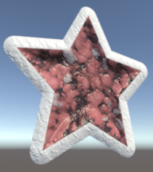
Each shader has two sections, an SDF part and a Contours part.
The SDF/Unlit shader is for unlit materials. Although it doesn't receive any lighting it can cast shadows and contribute to global illumination. It behaves like an emissive material.
The SDF/Metallic shader combines SDF rendering with physically-based shading (PBS), like Unity's standard shader.
The SDF/Specular shader combines SDF and PBS using Unity's specular workflow, instead of the metallic workflow.
Each shader also has an alternative version that is meant to be used with Unity's UI system. You will have to add a UIMaterialLink component to graphic objects that are masked, otherwise the materials won't work correctly.
Configuring the SDF
The SDF section of the shader UI is about the SDF texture and how to work with it.
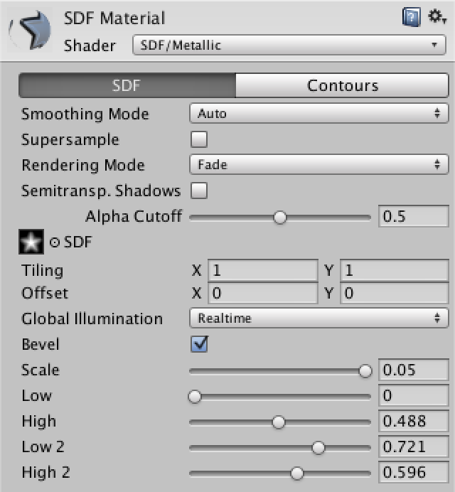
Smoothing Mode offers a choice between three ways in which the material's contours are smoothed. Without smoothing you'd get hard aliased edges.
Manual smoothing means that you select a smoothing range per contour. This allows you to create fuzzy edges. However, this range is fixed and doesn't depend on the on-screen size or angle of the contours. So close-up it's fuzzy, but go far enough away and the smoothing range will become smaller than a single display pixel, resulting in aliasing. This often isn't a problem when what you're rendering doesn't move around much in 3D, like UI elements.


Auto smoothing means that the smoothing range is automatically adjusted so it matches one display pixel everywhere. This results in hard but anti-aliased edges. This requires hardware support for derivative instructions.


Mixed smoothing combines manual and auto smoothing, adding them together to determine the total smoothing range. Use this when you want fuzzy edges that degrade to anti-aliased edges far away and at extreme view angles.
The Supersample option can greatly increase the visual quality of narrow shapes – especially with two contours – for small and angled renderings. It does this by evaluating the SDF four additional times per fragment, so it's expensive. Use it when you need good-looking results up to long distances, small scales, or when rotating freely. It also depends on derivative instructions.
As super-sampling does its own filtering, it doesn't work well with mipmaps. Except on mobile devices, mipmaps are automatically ignored when sampling the SDF texture when this option enabled.


Rendering Mode controls the blending mode of the material. It corresponds with the rendering mode of Unity's standard shaders, except that there is no opaque mode.
Cutout is alpha testing, which means a pixel is either filled or left empty. This means that you'll always get hard aliased edges on the outside of your shape, regardless of smoothing mode. You'd use this mode when you want the material to receive shadows. Also, it allows the lit shaders to work with the deferred rendering pipeline. The other modes will always use the forward rendering pipeline.
Fade is alpha blending, which allows for smooth blending, semi-transparency, and anti-aliased edges. It cannot receive shadows, but it can cast them just fine. Materials using this mode will always be rendered using the forward pipeline, even when you're using the deferred path.
Transparent is like the fade mode, but more realistic for semitransparent materials. Fade mode fades out the entire contribution of the material, like a ghost. Reflections will fade out as well. This mode keeps the reflected light intact, so you can get proper highlights on glass and such. However, you only want highlights visible inside the shape, not outside of it. So lighting still has to be faded out when beyond the shape's edge. As this is more work and a bit of a hack, only use Transparent mode for semitransparent surfaces.


The Semitransparent Shadows toggle allows you to enable semitransparent shadows, when using the fade or transparent rendering mode. Unity uses dithering to simulate semitransparent shadows, which often ends up looking bad, especially with hard shadows. So I made them optional. When disabled, shadows use the alpha cutoff.


UI shaders do not cast shadows.
Alpha Cutoff is used by the cutout rendering mode, and by shadows that aren't semitransparent. It sets the alpha threshold below which a fragment is discarded, resulting in an opening in either the shape or its shadow. It uses the final alpha value of each fragment, taking colors, textures, and contours into account.
SDF is the main texture of the material, along with its tiling and offset options. Only its alpha channel is used. Because of the nature of SDF sampling, this texture doesn't need to have a high resolution. It degrades much better than regular textures.
UI shaders expose the SDF texture to make previewing the material possible. Graphics elements will override this with their own SDF sprite.
Global Illumination is for when the material emits light, which is always the case for the unlit shader. The choice is between None, Realtime, and Baked. Keep in mind that you need to mark objects as Lightmap Static for this to have any effect.
UI shaders do not contribute to global illumination.
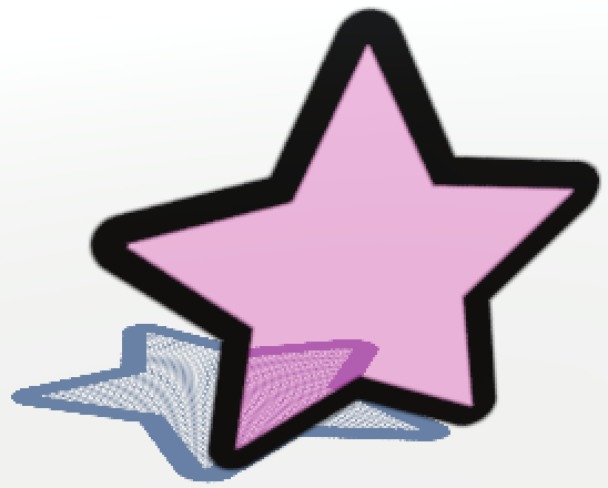
Bevel is a toggle that can be enabled to add a fake bevel using normals, which only works for lit shaders. It does this by sampling the SDF texture four times per fragment to construct normals on the fly, which is expensive. Because of the limited precision of texture data – 8 bits if uncompressed – this works best for narrow gradients. SDF textures with very wide transition gradients will suffer a lot from stratification artifacts.
Bevel Scale controls the apparent difference in height between the low and high areas. The larger the scale, the stronger the bevel effect.
Bevel Low and Bevel High control the distances at which the bevel is lowest and highest. You can get many different effects by playing with these settings. And if a single transition isn't enough, you can also throw in a second independent low–high pair. If you don't need the second pair, leave them at zero.

Configuring the Contours
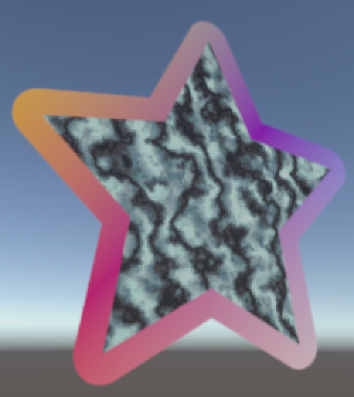
The contours section of the shader UI contains the shape's contour placement and material properties. There is always at least one contour, but you can enable a second, which functions as an outline.
The material properties are similar to those used by Unity's standard shader. Likewise, some features will only be enabled when necessary, so the shaders will only be as expensive as they need to be. Which properties are available varies per shader.
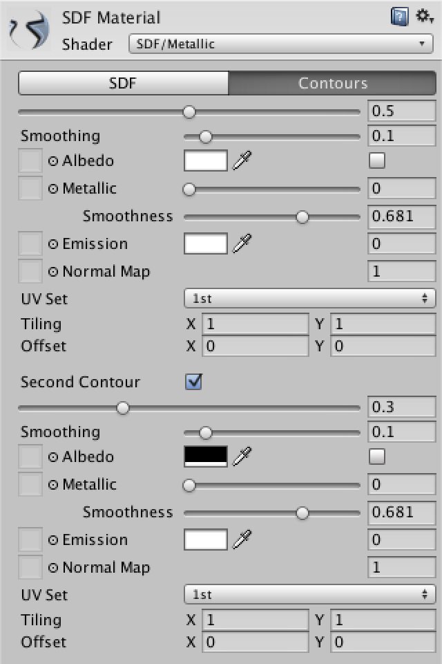
The large Contour sliders control the placement of the shape edges by means of the SDF. The sliders are independent, but the second one should be further from the inside than the first, so should have a lower value.


Smoothing is the size of the smoothing range, when using the manual or mixed smoothing mode. The two contours can have different settings, so one can be crisp while the other is blurred.

Albedo can either be a solid color tint, a texture, or both. The color will only be multiplied with the texture if it is something other than solid white, otherwise it will be ignored. The checkbox controls whether vertex colors should be used to tint the final albedo.
The unlit shader only supports albedo, which basically functions as emission.
Unity's UI system uses vertex colors to tint and fade sprites. Using the checkboxes, you can enable these effects per contour.
Metallic controls how metallic the shape is, when using the metallic shader. The specular shader has a Specular color instead. When using a texture map, it replaces the manual slider and colors, as well as smoothness. The metallic map stores the metallic value in the R component and smoothness in the A component. The specular map stores the specular color, and smoothness in the A component as well.
Smoothness is a slider that goes from very rough to extremely glossy. Don't set it all the way to 1, because that causes the specular highlight to collapse into a single pixel.
Emission consists of an optional texture map and an HDR tint. The scalar at the right shows the brightness of the tint, which is equal to its strongest component.
A Normal Map can be used to add fake surface irregularities. It has a scale that controls the strength of the effect. If it's negative it will change the direction of the normals.
UV Set controls which of the mesh's UV coordinate sets should be used to sample a contour's texture maps. The default is the first set, which is also used for the SDF texture. An alternative is to choose the second UV set, but keep in mind that this set is also used by baked lightmaps. You can also use the fourth UV set, which isn't claimed by anything else. The third UV set is omitted because it's used by dynamic GI, which overrules any coordinates you might provide yourself.
Each contour can also have its own texture Tiling and Offset settings, regardless of which UV set it uses.
UI shaders can only use the first two UV sets. The first set contains the sprite's UV coordinates. The second UV set is zero by default and has to be defined by a vertex modifier component. It is also possible to scale the second UV set by the texel size, so one UV unit covers one texel instead of the entire texture. This only works if the material has an albedo map.