Surface Displacement
Moving Vertices
- Adjust vertex positions on the GPU.
- Tessellate shadow geometry.
- Skip tessellating unseen triangles.
This tutorial follow Tessellation and combines it with vertex displacement to add more detail to geometry, on top of normal mapping.
This tutorial is made with Unity 2017.1.0.
Repositioning Vertices
Meshes are usually made up of triangles, which are always flat. The illusion of curvature is added via vertex normals. Normal maps can be used to add the illusion of more surface irregularities, smaller than individual mesh triangles. Beyond that, parallax mapping makes it possible to fake surface displacement. But all these approaches are illusions. The most robust way to make a surface more complex is by simply using more smaller triangles. Smaller triangles means that we have more vertices, enough to describe all surface details that we want. Unfortunately, that would result in much larger meshes, requiring more storage space, CPU and GPU memory, and memory bandwidth. Tessellation is a way around this problem, because it allows us to generate more triangles on the GPU when needed. This means the GPU has to do more work, but we can limit that to when it's really needed.
Cutting up existing triangles and interpolating the vertex data isn't enough to add more details. That just gives us more triangles that describe the same flat surface. We have to introduce new data, adjusting the triangle's vertices somehow.
A straightforward way to add more detail is to adjust the vertices of a mesh via a displacement map. The map is used to move vertices up or down, like a height field can be used to turn a flat terrain mesh into an actual landscape. This tutorial will cover how to do that.
Hijacking Parallax Mapping
To displace vertices, we need a displacement map. Although our Tessellation Shader doesn't have a property for such a map, it does have a parallax map that we used in the Parallax tutorial. The parallax map is really a displacement map, it's just that we used it to fake displacement. We can use the same map for actual displacement too.
Let's say that a shader can decide to use true vertex displacement instead of parallax mapping, simply by defining VERTEX_DISPLACEMENT_INSTEAD_OF_PARALLAX. If that macro is defined and we have a parallax map, then we must make sure that the parallax code doesn't get included, replacing it with proper vertex displacement code. To do this, undefine _PARALLAX_MAP and define a convenient VERTEX_DISPLACEMENT macro in My Lighting Input, when we have a parallax map and should use vertex displacement.
#include "UnityPBSLighting.cginc"
#include "AutoLight.cginc"

#if defined(_PARALLAX_MAP) && defined(VERTEX_DISPLACEMENT_INSTEAD_OF_PARALLAX)
	#undef _PARALLAX_MAP
	#define VERTEX_DISPLACEMENT 1
#endif
Let's also create macro aliases for the _ParallaxMap and _ParallaxStrength variables, so we can use _DisplacementMap and _DisplacementStrength instead. This makes it easier to get rid of the parallax code and switch to proper displacement properties, in case you like to do that later.
#if defined(_PARALLAX_MAP) && defined(VERTEX_DISPLACEMENT_INSTEAD_OF_PARALLAX)
	#undef _PARALLAX_MAP
	#define VERTEX_DISPLACEMENT 1
	#define _DisplacementMap _ParallaxMap
	#define _DisplacementStrength _ParallaxStrength
#endif
As we won't used both parallax mapping and tessellation at the same time, we can get rid of all definitions related to parallax in the CGINCLUDE block of Tessellation Shader. Instead, we only have to define VERTEX_DISPLACEMENT_INSTEAD_OF_PARALLAX.
CGINCLUDE #define BINORMAL_PER_FRAGMENT #define FOG_DISTANCE// #define PARALLAX_BIAS 0// #define PARALLAX_OFFSET_LIMITING// #define PARALLAX_RAYMARCHING_STEPS 10// #define PARALLAX_RAYMARCHING_INTERPOLATE// #define PARALLAX_RAYMARCHING_SEARCH_STEPS 3// #define PARALLAX_FUNCTION ParallaxRaymarching// #define PARALLAX_SUPPORT_SCALED_DYNAMIC_BATCHING#define VERTEX_DISPLACEMENT_INSTEAD_OF_PARALLAX ENDCG
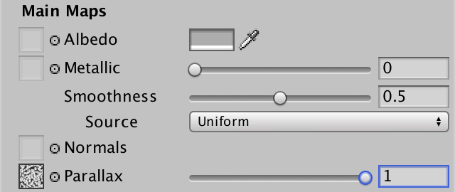
We'll perform vertex displacement in object space. To allow for a decent amount of displacement, increase the maximum strength from 0.1 to 1.
_ParallaxStrength ("Parallax Strength", Range(0, 1)) = 0
Changing the Vertex Position
Displacing vertices has to be done in the vertex program of My Lighting, before we use the vertex position for anything else. This means that if we want to support scaling and offsetting the displacement map like all other maps, we have to transform the texture coordinates before this point. So let's move the TRANSFORM_TEX lines before the first time the vertex position is used.
InterpolatorsVertex MyVertexProgram (VertexData v) {
	InterpolatorsVertex i;
	UNITY_INITIALIZE_OUTPUT(InterpolatorsVertex, i);
	UNITY_SETUP_INSTANCE_ID(v);
	UNITY_TRANSFER_INSTANCE_ID(v, i);

	i.uv.xy = TRANSFORM_TEX(v.uv, _MainTex);
	i.uv.zw = TRANSFORM_TEX(v.uv, _DetailTex);

	i.pos = UnityObjectToClipPos(v.vertex);
	i.worldPos.xyz = mul(unity_ObjectToWorld, v.vertex);
	#if FOG_DEPTH
		i.worldPos.w = i.pos.z;
	#endif
	i.normal = UnityObjectToWorldNormal(v.normal);

	#if defined(BINORMAL_PER_FRAGMENT)
		i.tangent = float4(UnityObjectToWorldDir(v.tangent.xyz), v.tangent.w);
	#else
		i.tangent = UnityObjectToWorldDir(v.tangent.xyz);
		i.binormal = CreateBinormal(i.normal, i.tangent, v.tangent.w);
	#endif

//	i.uv.xy = TRANSFORM_TEX(v.uv, _MainTex);
//	i.uv.zw = TRANSFORM_TEX(v.uv, _DetailTex);

	…
}
Once we have the final texture coordinates, we can sample the displacement map. This works the same as sampling the map for parallax mapping, so we'll use its green texture channel. However, because we're not doing this in the fragment program, there are no screen-space derivatives available, so the GPU cannot determine which mipmap level to use. We cannot use tex2D, instead we have to use tex2Dlod to specify an explicit mipmap level. This is done by supplying two additional texture coordinates, the third being an unused 3D coordinate and the fourth specifying the mip level. We'll just use 0 for both, effectively using no mipmaps.
	i.uv.xy = TRANSFORM_TEX(v.uv, _MainTex);
	i.uv.zw = TRANSFORM_TEX(v.uv, _DetailTex);

	#if VERTEX_DISPLACEMENT
		float displacement = tex2Dlod(_DisplacementMap, float4(i.uv.xy, 0, 0)).g;
	#endif
Like we do for parallax mapping, let's interpret the map so a value of 0.5 means no change, making it possible to move vertices both up and down. After that, factor in the displacement strength so we can control how much the vertices get moved in object space.
	#if VERTEX_DISPLACEMENT
		float displacement = tex2Dlod(_DisplacementMap, float4(i.uv.xy, 0, 0)).g;
		displacement = (displacement - 0.5) * _DisplacementStrength;
	#endif
If we were working with a default height field, then we'd just have to add the displacement to the vertex Y position at this point.
		float displacement = tex2Dlod(_DisplacementMap, float4(i.uv.xy, 0, 0)).g;
		displacement = (displacement - 0.5) * _DisplacementStrength;
		v.vertex.y += displacement;
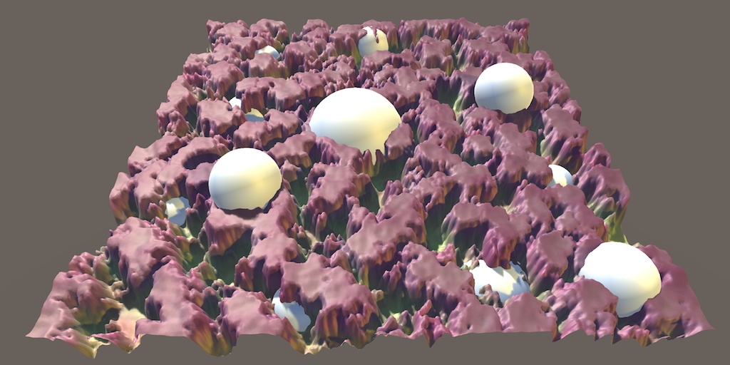
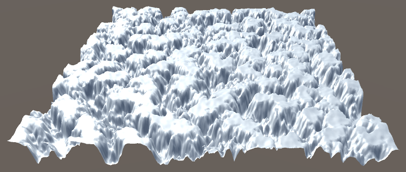
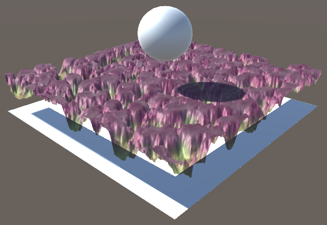
When applying this approach to a quad, the result will look like a mess of triangles that is still flat. That's because the quad is aligned with the XY plane in object space. If we want to perturb its otherwise flat surface, we have to adjust its Z coordinates instead. In general, a positive displacement should move vertices upward, from the point of view of the mesh. But not all meshes are planes. In the case of a sphere, it makes sense for displacement to move vertices outward. So in general it makes the most sense to displace along the vertex normal.
// v.vertex.y += displacement;v.vertex.xyz += v.normal * displacement;
Because we're using tessellation, the normal vectors of new vertices have been created via interpolation. So they're only guaranteed to be of unit length when all the vertex normals have the same orientation. To guarantee that we get unit-length normal vectors in general, we should normalize them before using them for displacement.
		v.normal = normalize(v.normal);
		v.vertex.xyz += v.normal * displacement;
Using Enough Triangles
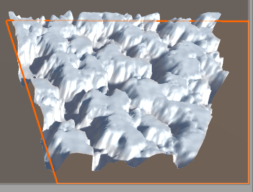
How much triangles are needed to support the desired detail level? It depends. Our displacement map at full strength produces quite a large change, so we need quite some triangles to make it look good. But we don't want to use more triangles than we need, so we should use the Edge tessellation mode instead of the Uniform mode.
When in Edge mode, tessellation is controlled by both the Edge Length property and the view distance. So how many triangles get used can vary a lot. A quad by itself contains only two triangles. We'd need a significant amount of tessellation to get something better than a low-poly jagged plane. We can help tessellation a lot by using a base mesh that has more triangles. For example, Unity's default plane mesh consists of 10×10 quads. Using that instead of a quad prevents complete degeneration and can also produce much higher vertex resolution than a quad, if needed.
Using a plane instead of a quad allows for a more fine-tuned tessellation, which makes it easier to achieve a visually uniform triangle density from all view angles.
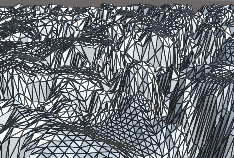
However, this still does not guarantee that all triangles end up with the same visual size. The tessellated triangles are only about the same size before their vertices are displaced. If a triangle's vertices end up displaced by different amount, it will become stretched along the normal vectors. Usually, vertex displacement isn't as extreme as the example that we use in this tutorial. If you're using it for a terrain mesh, the regular mesh should have sufficient resolution to represent the large features of the terrain. If you use a flat mesh as the basis for your terrain, consider displacing the original vertices before determining the tessellation factors, so coarse elevation gets taken into account when tessellating.
Normal Shading
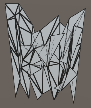
Up to this point we've been using the flat wireframe shading effect, to make it visually obvious how triangles get tessellated. But most of the time the goal is to enhance a mesh without tessellation being obvious. So let's revert to the default shading method. We do this by removing the geometry shader directive from the forward base, additive, and deferred passes of Tessellation Shader. We also have to replace the usage of the MyFlatWireframe include file with My Lighting in the same passes.
// #pragma geometry MyGeometryProgram…// #include "MyFlatWireframe.cginc"#include "My Lighting.cginc" #include "MyTessellation.cginc"
With the flat wireframe effect removed, we no longer need the wireframe properties either.
// _WireframeColor ("Wireframe Color", Color) = (0, 0, 0)// _WireframeSmoothing ("Wireframe Smoothing", Range(0, 10)) = 1// _WireframeThickness ("Wireframe Thickness", Range(0, 10)) = 1
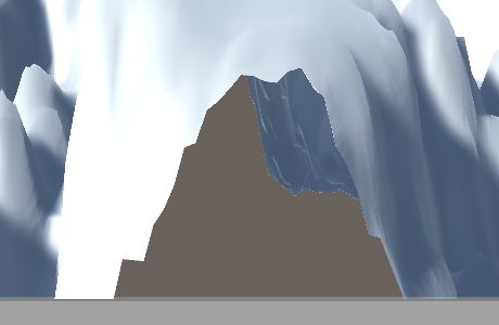
We are now back to normal shading, which ends up looking flat. That's because we displace vertex positions, but don't adjust the vertex normals to match. The exact end result depends on whether you're using the forward or deferred rendering path.

The visual difference between the rendering paths is due to shadows. We're not doing anything special for shadows yet, so we get the default shadow of a plane. In the case of forward rendering, both the depth pass used for screen-space shadows and the shadow casting is done with this plane. So our plane ends up not shadowing itself. In the case of deferred rendering, the tessellated geometry is used to fill the G-buffers, including the depth buffer. So the tessellated geometry that gets displaced downward ends up shadowed by the flat plane's shadow. We'll deal with shadows in the next section, so for now I'll use the forward rendering path.
To get proper shading for our displaced surface, we have to use the correct normal vectors. Fortunately, we have a matching normal map for our parallax map, so we can just use that.
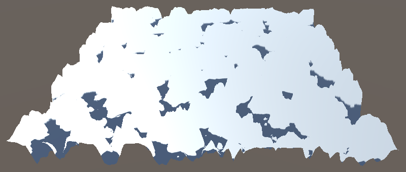
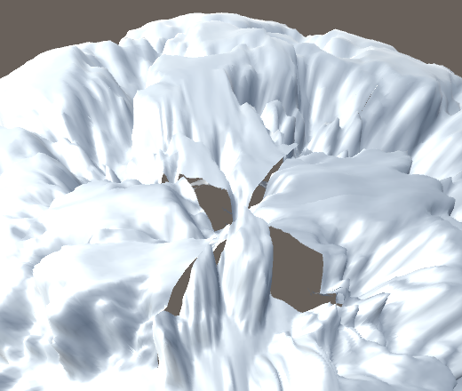
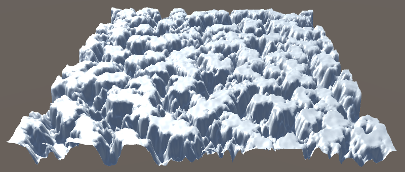
This approach works for any mesh, but it is important that there are no texture seams. Any seams would result in discontinuities. If we only used normal maps, this would lead to artifacts in shading that suggest hard edges where there should be none. In the case of displacement, it leads to gaps in the mesh, which is far worse. To see a good example of this, apply our tessellation material to a default sphere and inspect its poles.
At this point we have a displacement effect that's done via tessellation, replacing the parallax effect from an earlier tutorial. The big advantage of tessellation over parallax mapping is that it plays well with everything else, because it's just triangles. All techniques that work with regular triangles apply, and it intersects correctly with other geometry.
Shadows
Currently, shadows behave as if our plane were still flat. Only when using deferred rendering does the displaced geometry get used to receive shadows, but the cast shadow is still flat. We're now going to make sure that the shadows match the displaced surface.
Shadow Caster Pass with Tessellation
The first thing we have to do to makes shadows work, is to enabled tessellation for the shadow caster pass as well. This means that the shader target level of this pass has to be increased to 4.6.
#pragma target 4.6
As our displacement approach uses the parallax map, we have to add the appropriate shader feature for it, and also a feature for the Edge tessellation mode.
			#pragma shader_feature _SMOOTHNESS_ALBEDO
			#pragma shader_feature _PARALLAX_MAP
			#pragma shader_feature _TESSELLATION_EDGE
Then we have to replace our shadow's vertex program with the tessellation vertex program and add the required hull and domain programs.
// #pragma vertex MyShadowVertexProgram#pragma vertex MyTessellationVertexProgram #pragma fragment MyShadowFragmentProgram #pragma hull MyHullProgram #pragma domain MyDomainProgram
Those programs are defined in MyTessellation, so include it after My Shadows.
			#include "My Shadows.cginc"
			#include "MyTessellation.cginc"
Making Tessellated Shadows Work
At this point our shadow caster pass doesn't compile without errors. That's because My Shadows doesn't follow the exact same approach as My Lighting does. The first problem is that MyTessellation expects the vertex position field of VertexData to be named vertex, while it's known as position in My Shadows. Let's fix this by renaming it to vertex in My Shadows.
struct VertexData {
	UNITY_VERTEX_INPUT_INSTANCE_ID
//	float4 position : POSITION;
	float4 vertex : POSITION;
	float3 normal : NORMAL;
	float2 uv : TEXCOORD0;
};
The vertex position is used in two places in MyShadowVertexProgram, so change those references as well.
InterpolatorsVertex MyShadowVertexProgram (VertexData v) {
	…
	#if defined(SHADOWS_CUBE)
		i.position = UnityObjectToClipPos(v.vertex);
		i.lightVec =
			mul(unity_ObjectToWorld, v.vertex).xyz - _LightPositionRange.xyz;
	#else
		i.position = UnityClipSpaceShadowCasterPos(v.vertex.xyz, v.normal);
		i.position = UnityApplyLinearShadowBias(i.position);
	#endif

	…
}
The next problem is that shadows use less vertex data than the other three passes. Specifically, they don't require tangent, uv1, and uv2 data. We could add this data anyway, but that would needlessly make shadows slower. Instead, let's adjust MyTessellation so it can support less vertex data. We can do this by only including tangent, uv1, and uv2 in the TessellationControlPoint struct if appropriate macros are defined.
struct TessellationControlPoint {
	float4 vertex : INTERNALTESSPOS;
	float3 normal : NORMAL;
	#if TESSELLATION_TANGENT
		float4 tangent : TANGENT;
	#endif
	float2 uv : TEXCOORD0;
	#if TESSELLATION_UV1
		float2 uv1 : TEXCOORD1;
	#endif
	#if TESSELLATION_UV2
		float2 uv2 : TEXCOORD2;
	#endif
};
Using the same trick, we can control whether MyTessellationVertexProgram copies the relevant fields from the vertex data to the control point.
TessellationControlPoint MyTessellationVertexProgram (VertexData v) {
	TessellationControlPoint p;
	p.vertex = v.vertex;
	p.normal = v.normal;
	#if TESSELLATION_TANGENT
		p.tangent = v.tangent;
	#endif
	p.uv = v.uv;
	#if TESSELLATION_UV1
		p.uv1 = v.uv1;
	#endif
	#if TESSELLATION_UV2
		p.uv2 = v.uv2;
	#endif
	return p;
}
And also whether MyDomainProgram interpolates the data.
[UNITY_domain("tri")]
InterpolatorsVertex MyDomainProgram (
	…
) {
	…

	MY_DOMAIN_PROGRAM_INTERPOLATE(vertex)
	MY_DOMAIN_PROGRAM_INTERPOLATE(normal)
	#if TESSELLATION_TANGENT
		MY_DOMAIN_PROGRAM_INTERPOLATE(tangent)
	#endif
	MY_DOMAIN_PROGRAM_INTERPOLATE(uv)
	#if TESSELLATION_UV1
		MY_DOMAIN_PROGRAM_INTERPOLATE(uv1)
	#endif
	#if TESSELLATION_UV2
		MY_DOMAIN_PROGRAM_INTERPOLATE(uv2)
	#endif

	return MyVertexProgram(data);
}
This approach allows us to fine-tune what mesh data gets included while tessellating. We don't need tangent, uv1, and uv2 for shadows, but the other three passes might need them all. So let's define the relevant macros at the top of My Lighting Input.
#define TESSELLATION_TANGENT 1
#define TESSELLATION_UV1 1
#define TESSELLATION_UV2 1

#if defined(_PARALLAX_MAP) && defined(VERTEX_DISPLACEMENT_INSTEAD_OF_PARALLAX)
	…
#endif
The last problem is that My Lighting relies on the existence of MyVertexProgram, but we've named the vertex program for our shadow caster pass MyShadowVertexProgram. The quick solution is to define a macro alias in My Shadows. This way MyVertexProgram also works for shadows, without breaking existing shaders.
#define MyVertexProgram MyShadowVertexProgram

InterpolatorsVertex MyShadowVertexProgram (VertexData v) {
	…
}
Displacing Shadow Geometry
The shadows now get tessellated. The next step is to displace their vertices, for which we can use the same approach applied in My Lighting. First, copy the appropriate macro definitions to the top of My Shadows. The only difference is that we must also define SHADOWS_NEED_UV, if it wasn't already.
#if SHADOWS_SEMITRANSPARENT || defined(_RENDERING_CUTOUT)
	#if !defined(_SMOOTHNESS_ALBEDO)
		#define SHADOWS_NEED_UV 1
	#endif
#endif

#if defined(_PARALLAX_MAP) && defined(VERTEX_DISPLACEMENT_INSTEAD_OF_PARALLAX)
	#undef _PARALLAX_MAP
	#define VERTEX_DISPLACEMENT 1
	#define _DisplacementMap _ParallaxMap
	#define _DisplacementStrength _ParallaxStrength
	#if !defined(SHADOWS_NEED_UV)
		#define SHADOWS_NEED_UV 1
	#endif
#endif
Shadows didn't use the parallax map, so we have to add the required variables now.
sampler2D _ParallaxMap;
float _ParallaxStrength;
In the shadow vertex program, move the transformation of the texture coordinates above the usage of the vertex position.
InterpolatorsVertex MyShadowVertexProgram (VertexData v) {
	InterpolatorsVertex i;
	UNITY_SETUP_INSTANCE_ID(v);
	UNITY_TRANSFER_INSTANCE_ID(v, i);

	#if SHADOWS_NEED_UV
		i.uv = TRANSFORM_TEX(v.uv, _MainTex);
	#endif

	#if defined(SHADOWS_CUBE)
		i.position = UnityObjectToClipPos(v.vertex);
		i.lightVec =
			mul(unity_ObjectToWorld, v.vertex).xyz - _LightPositionRange.xyz;
	#else
		i.position = UnityClipSpaceShadowCasterPos(v.vertex.xyz, v.normal);
		i.position = UnityApplyLinearShadowBias(i.position);
	#endif

//	#if SHADOWS_NEED_UV
//		i.uv = TRANSFORM_TEX(v.uv, _MainTex);
//	#endif
	return i;
}
Then displace the vertex position.
	#if SHADOWS_NEED_UV
		i.uv = TRANSFORM_TEX(v.uv, _MainTex);
	#endif

	#if VERTEX_DISPLACEMENT
		float displacement = tex2Dlod(_DisplacementMap, float4(i.uv.xy, 0, 0)).g;
		displacement = (displacement - 0.5) * _DisplacementStrength;
		v.normal = normalize(v.normal);
		v.vertex.xyz += v.normal * displacement;
	#endif
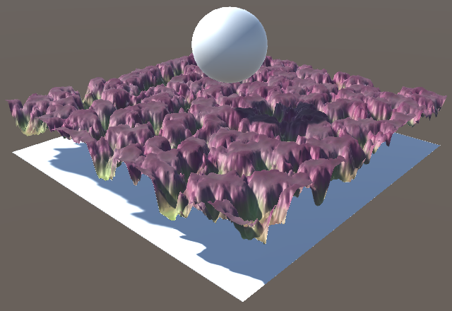
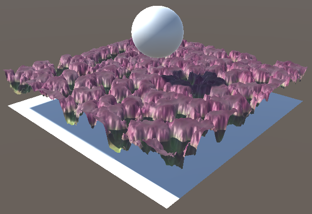
We now get correctly displaced shadows. Both receiving and casting shadows is now correct, for both rendering paths.
With shadows working, another advantage that tessellation has over parallax mapping is that we automatically get self-shadowing. It doesn't require any extra work.
Of course you have to keep the limitations of shadow mapping in mind. Also, when using Edge tessellation mode, the view distance for the shadow map is different than for the regular camera. This means that the tessellated shadow geometry doesn't exactly match the regular tessellated geometry, which can produce shadows artifacts. The finer the tessellation, the less of an issue this is.
Culling Triangles
Although tessellation is nice, it doesn't come cheap, especially when a high level of tessellation is desired. An important thing to realize is that every triangle of a mesh gets tessellated, regardless whether it ends up visible or not. However, it is possible to do something about that.
Not everything in a scene gets rendered. Only objects that lie inside the camera's view frustum can be seen. Those objects are send to the GPU by Unity, everything else gets culled. But if even a small portion of an object's bounding box lies inside the frustum, its entire mesh will be processed by the GPU, and thus tessellated. Fortunately, there is a way to skip triangles while tessellating, effectively culling them before the tessellation stage.
Skipping Some Triangles
The amount of tessellation is controlled by the edge and inside tessellation factors. A factor of 1 corresponds with no triangles being added. A higher factor results in more triangles. But it is also possible to use the factor 0. When one of the tessellation factors is zero, the original triangle is discarded and doesn't get rendered at all.
If we can figure out whether a triangle lies outside the view frustum, we can set its tessellation factors to 0, effectively performing frustum culling per triangle, on the GPU. Let's add a function to MyTessellation to figure this out. Place it above MyPatchConstantFunction, as that function will invoke it. We'll start with a very simple test. If all three vertices of a triangle have negative X coordinates, we'll consider it culled. We can use a boolean to communicate this.
bool TriangleIsCulled (float3 p0, float3 p1, float3 p2) {
	return p0.x < 0 && p1.x < 0 && p2.x < 0;
}
Use this function in MyPatchConstantFunction to check whether we can skip the triangle. If so, set all edge factors to zero. Otherwise, determine the factors are usual.
TessellationFactors MyPatchConstantFunction (
	InputPatch<TessellationControlPoint, 3> patch
) {
	float3 p0 = mul(unity_ObjectToWorld, patch[0].vertex).xyz;
	float3 p1 = mul(unity_ObjectToWorld, patch[1].vertex).xyz;
	float3 p2 = mul(unity_ObjectToWorld, patch[2].vertex).xyz;
	TessellationFactors f;
	if (TriangleIsCulled(p0, p1, p2)) {
		f.edge[0] = f.edge[1] = f.edge[2] = f.inside = 0;
	}
	else {
	    f.edge[0] = TessellationEdgeFactor(p1, p2);
	    f.edge[1] = TessellationEdgeFactor(p2, p0);
	    f.edge[2] = TessellationEdgeFactor(p0, p1);
		f.inside =
			(TessellationEdgeFactor(p1, p2) +
			TessellationEdgeFactor(p2, p0) +
			TessellationEdgeFactor(p0, p1)) * (1 / 3.0);
	}
	return f;
}
Frustum Culling
To perform actual frustum culling, we have to verify whether a triangle lies inside the camera's view frustum or outside of it. A frustum is a pyramid with its top cut off by a plane parallel to its base. The base and the sides of the pyramid can also be defined by planes. These planes form a system where the space inside the frustum is considered to lie above all six clip planes. So we have to check for each plane whether a point lies above or below it. Let's create a boolean function to check a single plane, returning true by default. Invoke that function inside TriangleIsCulled, replacing our test code.
bool TriangleIsBelowClipPlane (float3 p0, float3 p1, float3 p2) {
	return true;
}

bool TriangleIsCulled (float3 p0, float3 p1, float3 p2) {
//	return p0.x < 0 && p1.x < 0 && p2.x < 0;
	return TriangleIsBelowClipPlane(p0, p1, p2);
}
Because the camera could have any position and orientation, we cannot make any assumptions about its clip planes ahead of time. So we have to be able to work with planes of arbitrary orientation and position. In general, a plane can be defined by its normal vector that defines its local upward direction, plus an offset relative to the world origin. This data can be stored in a four-component vector, where the W component contains the offset. The plane vector corresponding to our previous test case of discarding triangles with negative X coordinates would thus be (1, 0, 0, 0). If we instead discarded triangles up to X coordinates of 2, the vector would be (1, 0, 0, 2) instead.
To figure out whether a point lies above or below the plane, we can project the vector to that point onto the plane's normal vector, via a dot product. If the result is negative, then their angle is larger than 90° and thus the point lies below the plane. The plane's offset must also be taken into account, by adding it into the calculation, for example by making it a dot product between (px, py, pz, 1) and the plane vector, where px, py, and pz and the point's coordinates. Adjust TriangleIsBelowClipPlane accordingly.
bool TriangleIsBelowClipPlane (float3 p0, float3 p1, float3 p2) {
	float4 plane = float4(1, 0, 0, 0);
	return
		dot(float4(p0, 1), plane) < 0 &&
		dot(float4(p1, 1), plane) < 0 &&
		dot(float4(p2, 1), plane) < 0;
}
The actual clip planes of the camera are made available via the unity_CameraWorldClipPlanes array, defined in UnityShaderVariables. It contains six plane definitions, for the left, right, bottom, top, near, and far planes. So to use the camera's left plane, we'd have to use unity_CameraWorldClipPlanes[0].
// float4 plane = float4(1, 0, 0, 0);float4 plane = unity_CameraWorldClipPlanes[0];
To make TriangleIsBelowClipPlane work for any of the camera's clip planes, add the plane index as an additional parameter and use that to select the appropriate camera plane.
bool TriangleIsBelowClipPlane (
	float3 p0, float3 p1, float3 p2, int planeIndex
) {
	float4 plane = unity_CameraWorldClipPlanes[planeIndex];
	return
		dot(float4(p0, 1), plane) < 0 &&
		dot(float4(p1, 1), plane) < 0 &&
		dot(float4(p2, 1), plane) < 0;
}
Now we can check all of the clip planes inside TriangleIsCulled. If the triangle ends up below any of them, then it cannot be visible and should be clipped. We have to check this for the left, right, bottom, and top planes. The near plane isn't really needed, because the view pyramid typically comes to a point only a short distance behind the camera. So it's not worth the extra effort to check the near plane. The far plane also isn't necessary, because at that distance tessellation would typically not happen anyway.
bool TriangleIsCulled (float3 p0, float3 p1, float3 p2) {
	return
		TriangleIsBelowClipPlane(p0, p1, p2, 0) ||
		TriangleIsBelowClipPlane(p0, p1, p2, 1) ||
		TriangleIsBelowClipPlane(p0, p1, p2, 2) ||
		TriangleIsBelowClipPlane(p0, p1, p2, 3);
}
Biased Culling
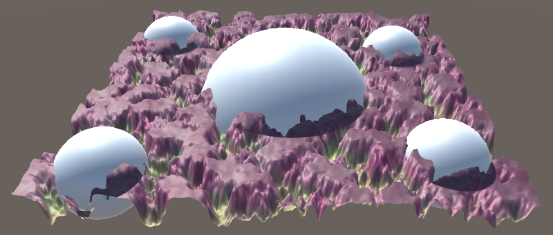
Because we're only clipping those triangles that we cannot see, we shouldn't be able to tell the difference between clipping and not clipping, aside from a possible difference in frame rate. However, this is only true if we don't displace any vertices. When vertices do get displaced, it is possible that displaced vertices end up inside the frustum, even though the original triangles lies outside of it. In the case of our displaced plane, you can verify this by looking at the plane at a shallow angle so some of its mesh triangles end up just below the bottom of the view. You'll quickly encounter holes as triangles suddenly vanish while they shouldn't.
The solution to this problem is to take the maximum displacement into consideration when determining whether a triangle lies below a clip plane or not. This can be done by adding a bias to TriangleIsBelowClipPlane. Instead of checking whether the dot product is less than zero, check whether it's below this bias.
bool TriangleIsBelowClipPlane (
	float3 p0, float3 p1, float3 p2, int planeIndex, float bias
) {
	float4 plane = unity_CameraWorldClipPlanes[planeIndex];
	return
		dot(float4(p0, 1), plane) < bias &&
		dot(float4(p1, 1), plane) < bias &&
		dot(float4(p2, 1), plane) < bias;
}
We should use the same bias for all plane checks, so add it as a parameter to TriangleIsCulled as well.
bool TriangleIsCulled (float3 p0, float3 p1, float3 p2, float bias) {
	return
		TriangleIsBelowClipPlane(p0, p1, p2, 0, bias) ||
		TriangleIsBelowClipPlane(p0, p1, p2, 1, bias) ||
		TriangleIsBelowClipPlane(p0, p1, p2, 2, bias) ||
		TriangleIsBelowClipPlane(p0, p1, p2, 3, bias);
}
Let's use a bias of 1 in MyPatchConstantFunction and see what happens.
	float bias = 1;
	if (TriangleIsCulled(p0, p1, p2, bias)) {
		f.edge[0] = f.edge[1] = f.edge[2] = f.inside = 0;
	}
A positive bias effectively pushes the clip planes upward, decreasing the size of the frustum. As a result, triangles get clipped too quickly, when they get near the edge of the view. A negative bias has the opposite effect, so triangles that lie outside of but still nearby the frustum don't get clipped. So we have to use a negative bias when using vertex displacement. As our maximum displacement in any dimension is equal to half the displacement strength, that's the negative bias that we need.
	float bias = 0;
	#if VERTEX_DISPLACEMENT
		bias = -0.5 * _DisplacementStrength;
	#endif

	if (TriangleIsCulled(p0, p1, p2, bias)) {
		f.edge[0] = f.edge[1] = f.edge[2] = f.inside = 0;
	}
We're now clipping as many triangles as possible, while guaranteeing that no holes will ever appear. Of course determining whether we should clip a triangle requires work too, so it won't improve performance for meshes that are fully in view, it actually makes it bit worse. But when you're rendering large meshes with a high amount of tessellation, and they often are only partially visible, then you can end up significantly improving your frame rate.
This concludes the introduction of tessellation. Now you know how to tessellate triangles and how to add geometric details via displacement mapping. This isn't the only thing you can do with tessellation. For example, there's also PN triangles, phong tessellation, procedural displacement, and more. Have fun experimenting with those methods!