Multiple Cameras
Camera Blending and Rendering Layers
- Render multiple cameras with different post FX settings.
- Layer cameras with custom blending.
- Support rendering layer masks.
- Mask lights per camera.
This is the 14th part of a tutorial series about creating a custom scriptable render pipeline. This time we revisit rendering with multiple cameras, now with post FX added.
This tutorial is made with Unity 2019.4.12f1 and upgraded to 2022.3.5f1.
Combining Cameras
Because culling, light processing, and shadow rendering is performed per camera it is a good idea to render as few cameras as possible per frame, ideally only one. But sometimes we do have to render multiple different points of view at the same time. Examples include split-screen multiplayer, rear-view mirrors, a top-down overlay, an in-game camera, and 3D character portraits.
Split Screen
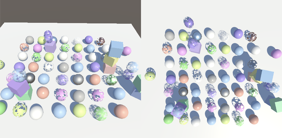
Let's begin by considering a split-screen scenario, consisting of two side-by-side cameras. The left camera has the width of its viewport rect set to 0.5. The right camera also has a width of 0.5 and has its X position set to 0.5. If we don't use post FX then this works as expected.
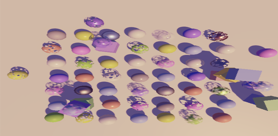
But if we enable post FX it fails. Both cameras render at the correct size but end up covering the entire camera target buffer, with only the last one visible.
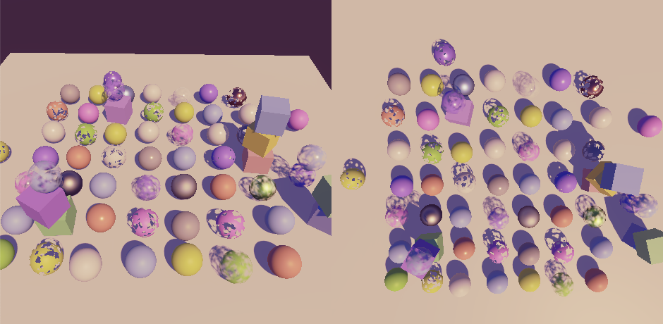
This happens because an invocation of SetRenderTarget also resets the viewport to cover the entire target. To apply the viewport to the final post FX pass we have to set the viewport after setting the target and before drawing. Let's do this by duplicating PostFXStack.Draw, renaming it to DrawFinal and invoking SetViewport on the buffer directly after SetRenderTarget, with the camera's pixelRect as an argument. As this is the final draw we can replace all but the source parameter with hard-coded values.
	void DrawFinal (RenderTargetIdentifier from) {
		buffer.SetGlobalTexture(fxSourceId, from);
		buffer.SetRenderTarget(
			BuiltinRenderTextureType.CameraTarget,
			RenderBufferLoadAction.DontCare, RenderBufferStoreAction.Store
		);
		buffer.SetViewport(camera.pixelRect);
		buffer.DrawProcedural(
			Matrix4x4.identity, settings.Material,
			(int)Pass.Final, MeshTopology.Triangles, 3
		);
	}
Invoke the new method instead of the regular Draw at the end of DoColorGradingAndToneMapping.
	void DoColorGradingAndToneMapping (int sourceId) {
		…
		Draw(…)
		DrawFinal(sourceId);
		buffer.ReleaseTemporaryRT(colorGradingLUTId);
	}
If you have a tile-based GPU you can get rendering artifacts around the edges of the rendered viewports, going beyond its bounds. This happens because the part of tile regions that got masked out contain junk data. We fix this by loading the target when not using a full viewport. This is not specific to Unity 2022, but I noticed this issue because Apple Silicon Macs have tile-based GPUs and support the don't-care option, but they didn't exist when I wrote this series.
	static Rect fullViewRect = new Rect(0f, 0f, 1f, 1f);

	…

		void DrawFinal (RenderTargetIdentifier from) {
		buffer.SetGlobalTexture(fxSourceId, from);
		buffer.SetRenderTarget(
			BuiltinRenderTextureType.CameraTarget,
			camera.rect == fullViewRect ?
				RenderBufferLoadAction.DontCare : RenderBufferLoadAction.Load,
			RenderBufferStoreAction.Store
		);
		…
	}
Layering Cameras
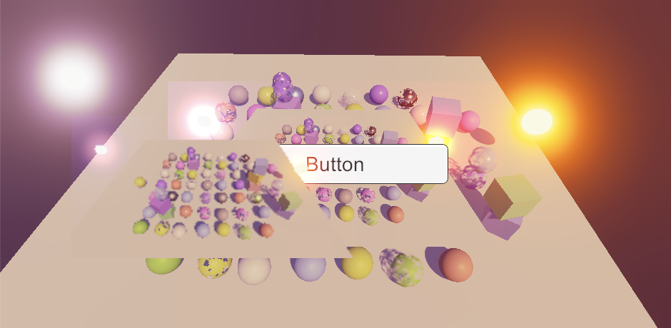
Besides rendering to separate areas we can also make camera viewports overlap. The simplest example is to use a regular main camera that covers the entire screen and then add a second camera that renders later with the same view but a smaller viewport. I reduced the second viewport to half size and centered it by settings its XY position to 0.25.
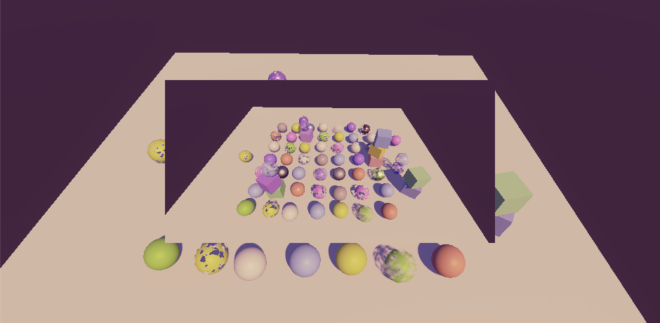
If we're not using post FX then we can turn the top camera layer into a partially-transparent overlay by settings it to clear depth only. This removes its skybox, revealing the layer below. But this doesn't work when post FX are used because then we force it to CameraClearFlags.Color€, so we'll see the camera's background color instead, which is dark blue by default.
One thing we could do to make layer transparency work with post FX is change the PostFXStack shader's final pass so it performs alpha blending instead of the default One Zero mode.
		Pass {
			Name "Final"

			Blend SrcAlpha OneMinusSrcAlpha

			HLSLPROGRAM
				#pragma target 3.5
				#pragma vertex DefaultPassVertex
				#pragma fragment FinalPassFragment
			ENDHLSL
		}
This does require us to always load the target buffer in FinalDraw.
	void DrawFinal (RenderTargetIdentifier from) {
		buffer.SetGlobalTexture(fxSourceId, from);
		buffer.SetRenderTarget(
			BuiltinRenderTextureType.CameraTarget,
			RenderBufferLoadAction.Load, RenderBufferStoreAction.Store
		);
		…
	}
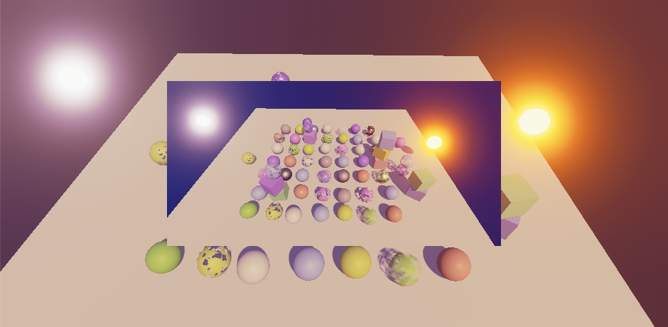
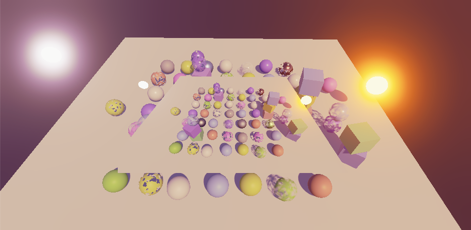
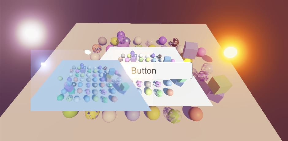
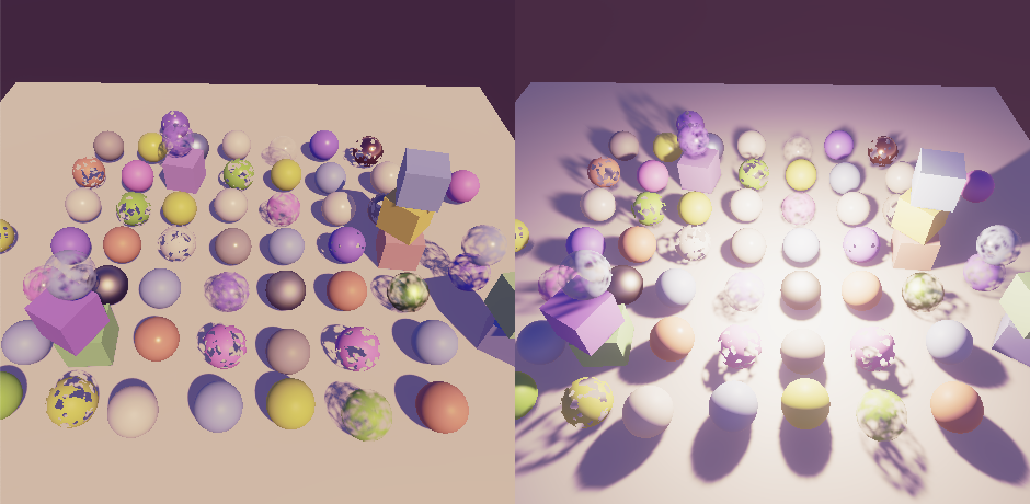
Now set the overlay camera's background color's alpha to zero. This appears to work, as long we disable bloom. I added two very bright emissive objects to make it obvious whether bloom is active or not.
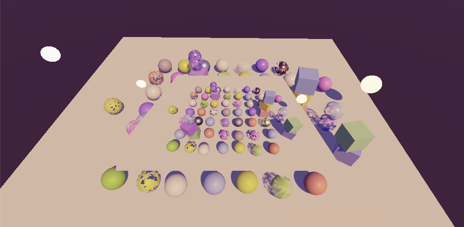
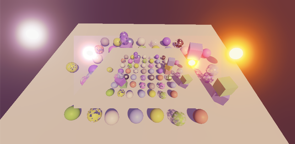
It doesn't work with bloom because that effect currently doesn't preserve transparency. We can fix this by adjusting the final bloom pass so it keeps the original transparency from the high resolution source texture. We have to adjust both BloomAddPassFragment and BloomScatterFinalPassFragment because either could be used for the final draw.
float4 BloomAddPassFragment (Varyings input) : SV_TARGET {
	…
	float4 highRes = GetSource2(input.screenUV);
	return float4(lowRes * _BloomIntensity + highRes.rgb, highRes.a);
}

…

float4 BloomScatterFinalPassFragment (Varyings input) : SV_TARGET {
	…
	float4 highRes = GetSource2(input.screenUV);
	lowRes += highRes.rgb - ApplyBloomThreshold(highRes.rgb);
	return float4(lerp(highRes.rgb, lowRes, _BloomIntensity), highRes.a);
}
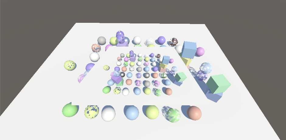
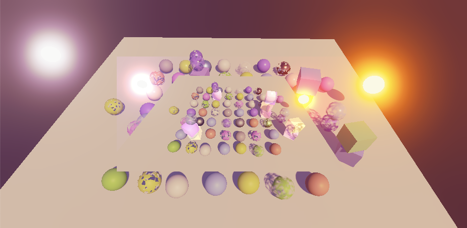
Transparency now works with bloom, but the bloom's contribution to transparent areas is no longer visible. We can preserve the bloom by switching the final pass to premultiplied alpha blending. This does require us to set the camera's background color to solid transparent black, as it will get added to the layer below.
			Name "Final"

			Blend One OneMinusSrcAlpha
Layered Alpha
Our current layering approach only works if our shaders produce sensible alpha values that work with camera layer blending. We didn't care about the written alpha values earlier because we never used them for anything. But now if two objects with alpha 0.5 end up rendering to the same texel the final alpha of that texel should be 0.25. And when either of the alpha values is 1 then the result should always be 1. And when the second alpha is zero then the original alpha should be retained. All those cases are covered by using One OneMinusSrcAlpha when blending alpha. We can configure the shader's blending mode for the alpha channel separately from the colors, by adding a comma followed by the modes for alpha after the color blend modes. Do this for the regular pass of both our Lit and Unlit shaders.
Blend [_SrcBlend] [_DstBlend], One OneMinusSrcAlpha
This will work as long as appropriate alpha values are used, which typically means that objects that write depth should always produce an alpha of 1 as well. This seems straightforward for opaque materials, but if they end up using a base map which also contains varying alpha it will go wrong. And it can also go wrong for clip materials because they rely on an alpha threshold to discard fragments. If a fragment is clipped it goes fine, but if it isn't its alpha should become 1.
The quickest way to make sure that alpha behaves correctly for our shaders is to add _ZWrite to the UnityPerMaterial buffer, both in LitInput and UnlitInput.
	UNITY_DEFINE_INSTANCED_PROP(float, _Cutoff)
	UNITY_DEFINE_INSTANCED_PROP(float, _ZWrite)
Then add a GetFinalAlpha function with an alpha parameter to both input files. It returns 1 if _ZWrite is set to 1 and the provided value otherwise.
float GetFinalAlpha (float alpha) {
	return INPUT_PROP(_ZWrite) ? 1.0 : alpha;
}
Filter the surface alpha through this function in LitPassFragment to get the correct alpha value at the end.
float4 LitPassFragment (Varyings input) : SV_TARGET {
	…
	return float4(color, GetFinalAlpha(surface.alpha));
}
And do the same for the base alpha in UnlitPassFragment.
float4 UnlitPassFragment (Varyings input) : SV_TARGET {
	…
	return float4(base.rgb, GetFinalAlpha(base.a));
}
Custom Blending
Blending with the previous camera layer only makes sense for overlay cameras. The bottom camera would blend with whatever the initial contents of the camera target are, which are either random or the accumulation of previous frames, unless the editor provides a cleared target. So the first camera should use the One Zero mode for blending. To support replacement, overlay, and more exotic layering options we'll add a configurable final blend mode to cameras that gets used when post FX are enabled. We'll create a new serializable CameraSettings configuration class for these settings, like we did for shadows. Wrap both source and destination blend modes in a single inner FinalBlendMode struct for convenience, then set it to One Zero blending by default.
using System;
using UnityEngine.Rendering;

[Serializable]
public class CameraSettings {

	[Serializable]
	public struct FinalBlendMode {

		public BlendMode source, destination;
	}

	public FinalBlendMode finalBlendMode = new FinalBlendMode {
		source = BlendMode.One,
		destination = BlendMode.Zero
	};
}
We cannot directly add these settings to Camera components, so we'll create a supplementary CustomRenderPipelineCamera component. It can only be added once to a game object that is a camera, and only once. Give it a CameraSettings configuration field with accompanying getter property. Because the settings are a class the property has to ensure that one exists, so create a new settings object instance if needed. This would be the cause if the component hasn't been serialized by the editor yet, or after adding one to a camera at runtime.
using UnityEngine;

[DisallowMultipleComponent, RequireComponent(typeof(Camera))]
public class CustomRenderPipelineCamera : MonoBehaviour {

	[SerializeField]
	CameraSettings settings = default;

	public CameraSettings Settings => settings ?? (settings = new CameraSettings());
}
Now we can get the camera's CustomRenderPipelineCamera component at the start of CameraRenderer.Render. To support cameras without custom settings we'll check if our component exists. If so we use its settings, otherwise we'll use a default settings objects that we create once and store a reference to in a static field. Then we pass along the final blend mode when we set up the stack.
	static CameraSettings defaultCameraSettings = new CameraSettings();

	…

	public void Render (…) {
		this.context = context;
		this.camera = camera;

		var crpCamera = camera.GetComponent<CustomRenderPipelineCamera>();
		CameraSettings cameraSettings =
			crpCamera ? crpCamera.Settings : defaultCameraSettings;

		…
			postFXStack.Setup(
			context, camera, postFXSettings, useHDR, colorLUTResolution,
			cameraSettings.finalBlendMode
		);
		…
	}
PostFXStack now has to keep track of the camera's final blend mode.
	CameraSettings.FinalBlendMode finalBlendMode;

	…

	public void Setup (
		ScriptableRenderContext context, Camera camera, PostFXSettings settings,
		bool useHDR, int colorLUTResolution, CameraSettings.FinalBlendMode finalBlendMode
	) {
		this.finalBlendMode = finalBlendMode;
		…
	}
So it can set new _FinalSrcBlend and _FinalDstBlend float shader properties at the start of DrawFinal. Also, we now also always need to load the target buffer if the destination blend mode isn't zero.
	int
		finalSrcBlendId = Shader.PropertyToID("_FinalSrcBlend"),
		finalDstBlendId = Shader.PropertyToID("_FinalDstBlend");

	…

	void DrawFinal (RenderTargetIdentifier from) {
		buffer.SetGlobalFloat(finalSrcBlendId, (float)finalBlendMode.source);
		buffer.SetGlobalFloat(finalDstBlendId, (float)finalBlendMode.destination);
		buffer.SetGlobalTexture(fxSourceId, from);
		buffer.SetRenderTarget(
			BuiltinRenderTextureType.CameraTarget,
			finalBlendMode.destination == BlendMode.Zero && camera.rect == fullViewRect ?
				RenderBufferLoadAction.DontCare : RenderBufferLoadAction.Load,
			RenderBufferStoreAction.Store
		);
		…
	}
Finally, use the new properties in the final pass instead of hard-coded blend modes.
			Name "Final"

			Blend [_FinalSrcBlend] [_FinalDstBlend]
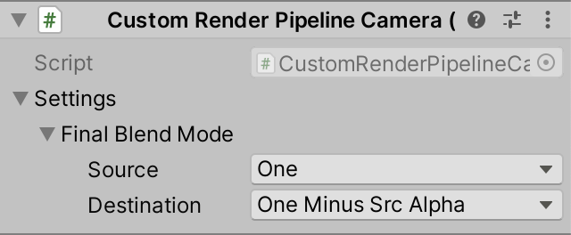
From now on cameras without our settings will overwrite the target buffer's contents, due to the default One Zero final blend mode. Overlay cameras have to be given a different final blend mode, typically One OneMinusSrcAlpha.
Render Textures
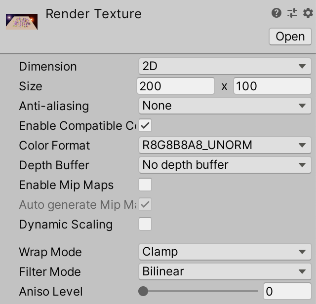
Besides creating a split-screen display or directly layering cameras it's also common to use a camera for an in-game display, or as part of the GUI. In these cases the camera's target has to be a render texture, either an asset or one created at runtime. As an example I created a 200×100 render texture via Assets / Create / Render Texture. I gave it no depth buffer because I render a camera with post FX to it, which creates its own intermediate render texture with a depth buffer.
I then created a camera that renders the scene to this texture, by hooking it up to the camera's Target Texture property.
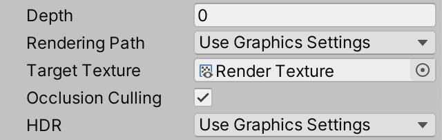
As with regular rendering the bottom camera has to use One Zero for its final blend mode. The editor will initially present a clear black texture, but after that the render texture will contain whatever was last rendered to it. Multiple cameras can render to the same render texture, with any viewport, as normal. The only difference is that Unity automatically renders cameras with render texture targets before those that render to a display. First cameras with target textures are rendered in order of increasing depth, then those without.
Unity UI
The render texture can be used like any regular texture. To display it via Unity's UI we'll have to use a game object with a raw image component, created via GameObject / UI / Raw Image.
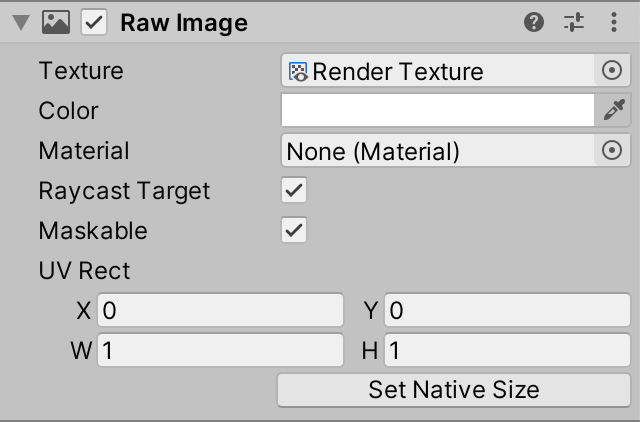
The raw image uses the default UI material, which performs standard SrcAlpha OneMinusSrcAlpha blending. So transparency works, but bloom isn't additive and unless the texture is displayed pixel-perfect bilinear filtering will make the camera's black background color visible as a dark outline around transparent edges.
To support other blend modes we'll have to create a custom UI shader. We'll simply do this by duplicating the Default-UI shader, adding support for configurable blending via _SrcBlend and _DstBlend shader properties. I also adjusted the shader code to better match the style of this tutorial series.
Shader "Custom RP/UI Custom Blending" {
	Properties {
		[PerRendererData] _MainTex ("Sprite Texture", 2D) = "white" {}
		_Color ("Tint", Color) = (1,1,1,1)
		_StencilComp ("Stencil Comparison", Float) = 8
		_Stencil ("Stencil ID", Float) = 0
		_StencilOp ("Stencil Operation", Float) = 0
		_StencilWriteMask ("Stencil Write Mask", Float) = 255
		_StencilReadMask ("Stencil Read Mask", Float) = 255
		_ColorMask ("Color Mask", Float) = 15
		[Toggle(UNITY_UI_ALPHACLIP)] _UseUIAlphaClip ("Use Alpha Clip", Float) = 0
		[Enum(UnityEngine.Rendering.BlendMode)] _SrcBlend ("Src Blend", Float) = 1
		[Enum(UnityEngine.Rendering.BlendMode)] _DstBlend ("Dst Blend", Float) = 0
	}

	SubShader {
		Tags {
			"Queue" = "Transparent"
			"IgnoreProjector" = "True"
			"RenderType" = "Transparent"
			"PreviewType" = "Plane"
			"CanUseSpriteAtlas" = "True"
		}

		Stencil {
			Ref [_Stencil]
			Comp [_StencilComp]
			Pass [_StencilOp]
			ReadMask [_StencilReadMask]
			WriteMask [_StencilWriteMask]
		}

		Blend [_SrcBlend] [_DstBlend]
		ColorMask [_ColorMask]
		Cull Off
		ZWrite Off
		ZTest [unity_GUIZTestMode]

		Pass { … }
	}
}
And here is the pass, unmodified except for style.
		Pass {
			Name "Default"

			CGPROGRAM
			#pragma vertex UIPassVertex
			#pragma fragment UIPassFragment
			#pragma target 2.0

			#include "UnityCG.cginc"
			#include "UnityUI.cginc"

			#pragma multi_compile_local _ UNITY_UI_CLIP_RECT
			#pragma multi_compile_local _ UNITY_UI_ALPHACLIP

			struct Attributes {
				float4 positionOS : POSITION;
				float4 color : COLOR;
				float2 baseUV : TEXCOORD0;
				UNITY_VERTEX_INPUT_INSTANCE_ID
			};

			struct Varyings {
				float4 positionCS : SV_POSITION;
				float2 positionUI : VAR_POSITION;
				float2 baseUV : VAR_BASE_UV;
				float4 color : COLOR;
				UNITY_VERTEX_OUTPUT_STEREO
			};

			sampler2D _MainTex;
			float4 _MainTex_ST;
			float4 _Color;
			float4 _TextureSampleAdd;
			float4 _ClipRect;

			Varyings UIPassVertex (Attributes input) {
				Varyings output;
				UNITY_SETUP_INSTANCE_ID(input);
				UNITY_INITIALIZE_VERTEX_OUTPUT_STEREO(output);
				output.positionCS = UnityObjectToClipPos(input.positionOS);
				output.positionUI = input.positionOS.xy;
				output.baseUV = TRANSFORM_TEX(input.baseUV, _MainTex);
				output.color = input.color * _Color;
				return output;
			}

			float4 UIPassFragment (Varyings input) : SV_Target {
				float4 color =
					(tex2D(_MainTex, input.baseUV) + _TextureSampleAdd) * input.color;
				#if defined(UNITY_UI_CLIP_RECT)
					color.a *= UnityGet2DClipping(input.positionUI, _ClipRect);
				#endif
				#if defined(UNITY_UI_ALPHACLIP)
					clip (color.a - 0.001);
				#endif
				return color;
			}
			ENDCG
		}
Post FX Settings Per Camera
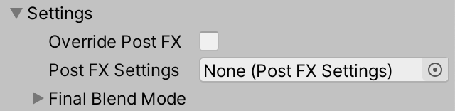
When working with multiple cameras it should be possible to use different post FX per camera, so let's add support for it. Give CameraSettings a toggle to control whether it overrides the global post FX settings, along with its own PostFXSettings field.
	public bool overridePostFX = false;

	public PostFXSettings postFXSettings = default;
Have CameraRenderer.Render check whether the camera overrides the post FX settings. If so replace the settings provided by the render pipeline with the camera's.
		var crpCamera = camera.GetComponent<CustomRenderPipelineCamera>();
		CameraSettings cameraSettings =
			crpCamera ? crpCamera.Settings : defaultCameraSettings;

		if (cameraSettings.overridePostFX) {
			postFXSettings = cameraSettings.postFXSettings;
		}
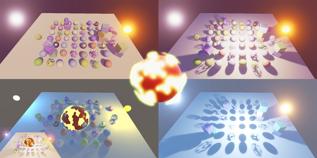
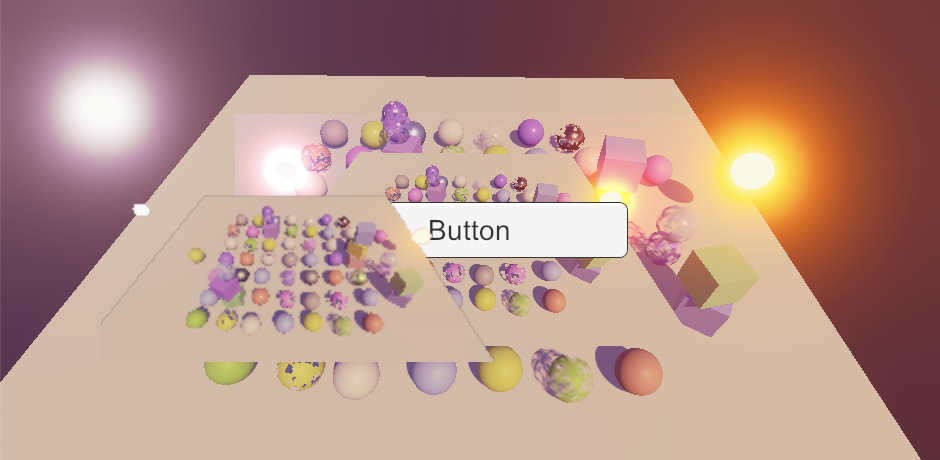
Now each camera can either use the default or custom post FX. For example, I made the bottom camera use the default, turned off post FX for the overlay camera, and gave the render texture camera different post FX with a cold temperature shift and neutral tone mapping.
Rendering Layers
When showing multiple camera views at the same time we don't always want to render the same scene for all cameras. For example, we could be rendering the main view and a character portrait. Unity supports only a single global scene at a time, so we must use a way to limit what each camera sees.
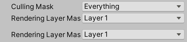
Culling Masks
Every game object belongs to a single layer. The scene window can filter which layers it displays via the Layers dropdown menu at the top right of the editor. Likewise, each camera has a Culling Mask property that can be used to limit what it displays the same way. This mask is applied during the culling step of rendering.
Each object belongs to exactly one layer, while culling masks can include multiple layers. For example, you could have two cameras that both render the Default layer while one also renders Ignore Raycasts while the other instead also renders Water. Thus some objects show up for both cameras while others are only visible to one or the other, and yet other objects might not get rendered at all.
Lights also have culling masks. The idea is that an object that's culled for a light behaves as if that light doesn't exists. The object isn't lit by the light and doesn't cast a shadow for it. But if we try this out with a directional light only its shadows are affected.
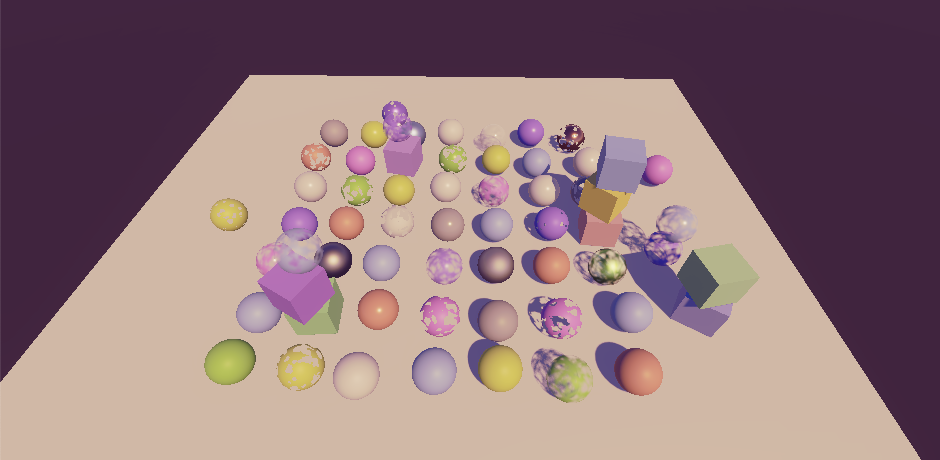
The same happens if we tried it with another light type, if our RP's Use Lights Per Object option is disabled.
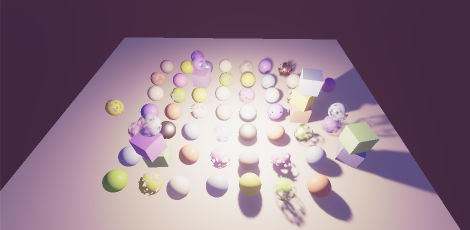
If Use Lights Per Object is enabled then light culling works as it should, but for point and spot lights only.
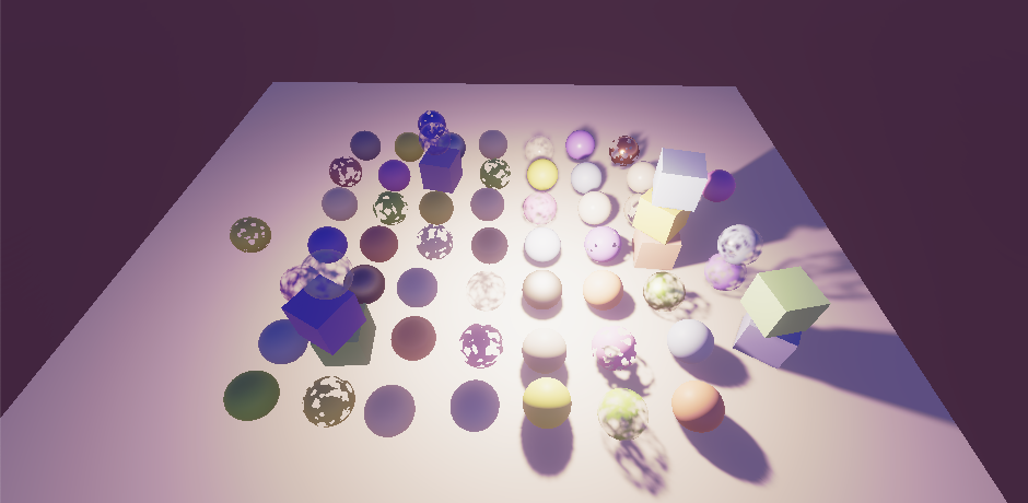
We get these results because the light's culling mask gets applied by Unity when it sends the per-object light indices to the GPU. So if we don't use those culling doesn't work. And it never works for directional lights because we always apply those to everything. Shadows do always get culled correctly because the light's culling mask is used like a camera's when rendering the shadow casters from the light's point of view.
We cannot fully support culling masks for lights with our current approach. This limitation isn't a showstopper, HDRP also doesn't support culling masks for lights. Unity provides rendering layers as an alternative for SRPs. There are two benefits of using rendering layers instead of game-object layers. First, renderers aren't limited to only a single layer, which makes them much more flexible. Second, rendering layers aren't used for anything else, unlike default layers which are also used for physics.
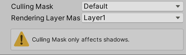
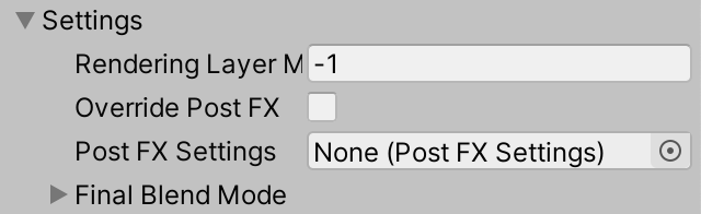
Before we move on to rendering layers, let's display a warning in the light's inspector when its culling mask is set to something else than Everything. The light's culling mask is made available via its cullingMask integer property with −1 representing all layers. If the target of CustomLightEditor has its mask set to anything else invoke EditorGUILayout.HelpBox at the end of OnInspectorGUI, with a string indicating culling masks only affect shadows and MessageType.Warning to show a warning icon.
	public override void OnInspectorGUI() {
		…

		var light = target as Light;
		if (light.cullingMask != -1) {
			EditorGUILayout.HelpBox(
				"Culling Mask only affects shadows.",
				MessageType.Warning
			);
		}
	}
We can be a bit more specific, mentioning that the Use Lights Per Object setting makes a difference for lights that aren't directional.
			EditorGUILayout.HelpBox(
				light.type == LightType.Directional€ ?
					"Culling Mask only affects shadows." :
					"Culling Mask only affects shadow unless Use Lights Per Objects is on.",
				MessageType.Warning
			);
Adjusting the Rendering Layer Mask
When an SRP is used the inspectors of lights and MeshRenderer components expose a Rendering Layer Mask property that is hidden when the default RP is used.
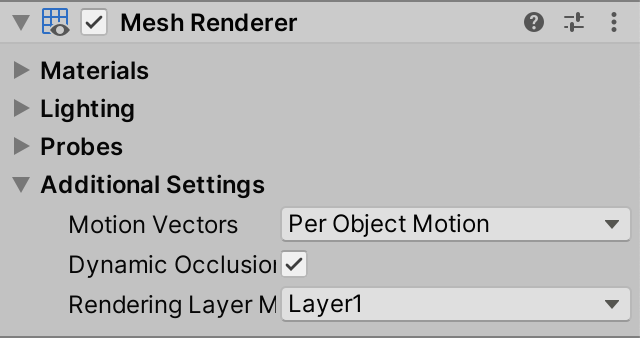
MeshRenderer.By default the dropdown shows 32 layers, named Layer1, Layer2, etc. The names of these layers can be configured per RP, by overriding the RenderPipelineAsset.renderingLayerMaskNames getter property. As this is purely cosmetic for the dropdown menu we only need to do this for the Unity Editor. So turn CustomRenderPipelineAsset into a partial class.
public partial class CustomRenderPipelineAsset : RenderPipelineAsset { … }
And then create an editor-only script asset for it that overrides the property. It returns a string array, which we can create in a static constructor method. We'll start with the same names as the default, except with a space in between the Layer word and the number.
partial class CustomRenderPipelineAsset {

#if UNITY_EDITOR

	static string[] renderingLayerNames;

	static CustomRenderPipelineAsset () {
		renderingLayerNames = new string[32];
		for (int i = 0; i < renderingLayerNames.Length; i++) {
			renderingLayerNames[i] = "Layer " + (i + 1);
		}
	}

	public override string[] renderingLayerMaskNames => renderingLayerNames;

#endif
}
This changes the rendering layer labels slightly. It works fine for MeshRenderer components, but unfortunately the light's property doesn't respond to changes. The rendering layer dropdown menu shows up, but adjustments don't get applied. We cannot directly fix this, but can add our own version of the property that does work. Begin by creating a GUIContent for it in CustomLightEditor, with the same label and a tooltip indicating that this is a functional version of the property above it.
	static GUIContent renderingLayerMaskLabel =
		new GUIContent("Rendering Layer Mask", "Functional version of above property.");
Then create a DrawRenderingLayerMask method that is an alternative of LightEditor.DrawRenderingLayerMask that does assign a changed value back to the property. To make the dropdown menu use the RP's layer names we cannot simply rely on EditorGUILayout.PropertyField. We have to grab the relevant property from the settings, make sure to handle mixed values of a multi-selection, grab the mask as an integer, show it, and assign a changed value back to the property. It's the last step that's missing from the default light inspector's version.
Showing the dropdown is done by invoking EditorGUILayout.MaskField with the label, mask, and GraphicsSettings.currentRenderPipeline.renderingLayerMaskNames as arguments.
	void DrawRenderingLayerMask () {
		SerializedProperty property = settings.renderingLayerMask;
		EditorGUI.showMixedValue = property.hasMultipleDifferentValues;
		EditorGUI.BeginChangeCheck();
		int mask = property.intValue;
		mask = EditorGUILayout.MaskField(
			renderingLayerMaskLabel, mask,
			GraphicsSettings.currentRenderPipeline.renderingLayerMaskNames
		);
		if (EditorGUI.EndChangeCheck()) {
			property.intValue = mask;
		}
		EditorGUI.showMixedValue = false;
	}
Invoke the new method directly after invoking base.OnInspectorGUI, so the extra Rendering Layer Mask property is shown directly below the nonfunctional one. Also, we now have to always invoke ApplyModifiedProperties to make sure that changes to the rendering layer mask are applied to the light.
	public override void OnInspectorGUI() {
		base.OnInspectorGUI();
		DrawRenderingLayerMask();

		if (
			!settings.lightType.hasMultipleDifferentValues &&
			(LightType)settings.lightType.enumValueIndex == LightType.Spot
		)
		{
			settings.DrawInnerAndOuterSpotAngle();
			//settings.ApplyModifiedProperties();
		}

		settings.ApplyModifiedProperties();

		…
	}
Our version of the property does apply changes, except that selecting the Everything or Layer 32 options produce the same result as if Nothing was selected. This happens because the light's rendering layer mask is internally stored as an unsigned integer, a uint. This makes sense because it is used as a bit mask, but SerializedProperty only supports getting and setting a signed integer value.
The Everything option is represented by −1, which the property clamps to zero. And Layer 32 corresponds to the highest bit, which represents a number one greater than int.MaxValue, which the property also replaces with zero.
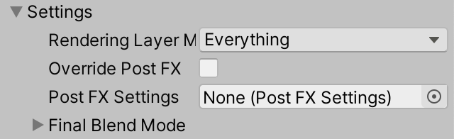
We can solve the second problem by simply removing the last layer, by reducing the amount of rendering layer names to 31. That's still plenty of layers. HDRP only supports eight.
renderingLayerNames = new string[31];
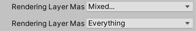
By removing one layer the Everything option is now represented by a a value with all but the highest bit set, which matches int.MaxValue. So we can solve the first problem by showing −1 while storing int.MaxValue. The default property doesn't do this, which is why it shows Mixed... instead of Everything when appropriate. HDRP also suffers from this.
		int mask = property.intValue;
		if (mask == int.MaxValue) {
			mask = -1;
		}
		mask = EditorGUILayout.MaskField(
			renderingLayerMaskLabel, mask,
			GraphicsSettings.currentRenderPipeline.renderingLayerMaskNames
		);
		if (EditorGUI.EndChangeCheck()) {
			property.intValue = mask == -1 ? int.MaxValue : mask;
		}
We can finally correctly adjust the rendering layers mask property of lights. But the mask isn't used by default, so nothing changed. We can apply it to shadows by enabling useRenderingLayerMaskTest of the ShadowDrawingSettings in Shadows. Do this for all lights, so in RenderDirectionalShadows, RenderSpotShadows, and RenderPointShadows. We can now eliminate shadows by configuring rendering layer masks of objects and lights.
		var shadowSettings = new ShadowDrawingSettings(
			…
		) {
			useRenderingLayerMaskTest = true
		};
Sending a Mask to the GPU
To apply the rendering layer mask to lighting calculations of our Lit shader the masks of both the objects and the lights have to be available on the GPU side. To access the object's mask we have to add a float4 unity_RenderingLayer field to the UnityPerDraw structure in UnityInput, directly below unity_WorldTransformParams. The mask is stored in its first component.
	real4 unity_WorldTransformParams;

	float4 unity_RenderingLayer;
We'll add the mask to our Surface struct, as a uint because it is a bit mask.
struct Surface {
	…
	uint renderingLayerMask;
};
When setting the surface's mask in LitPassFragment we have to use the asuint intrinsic function. This gets use the raw data, without performing a numeric type conversion from float to uint, which would alter the bit pattern.
	surface.dither = InterleavedGradientNoise(input.positionCS.xy, 0);
	surface.renderingLayerMask = asuint(unity_RenderingLayer.x);
We have to do the same for the Light struct, so give it a uint field for its rendering layer mask as well.
struct Light {
	…
	uint renderingLayerMask;
};
We're responsible for sending the mask to the GPU. Let's do this by storing it in the unused fourth component of the _DirectionalLightDirections and _OtherLightDirections arrays. Add the AndMasks suffix to their names for clarity.
CBUFFER_START(_CustomLight)
	…
	float4 _DirectionalLightDirectionsAndMasks[MAX_DIRECTIONAL_LIGHT_COUNT];
	…
	float4 _OtherLightDirectionsAndMasks[MAX_OTHER_LIGHT_COUNT];
	…
CBUFFER_END
Copy the mask in GetDirectionalLight.
	light.direction = _DirectionalLightDirectionsAndMasks[index].xyz;
	light.renderingLayerMask = asuint(_DirectionalLightDirectionsAndMasks[index].w);
And in GetOtherLight.
	float3 spotDirection = _OtherLightDirectionsAndMasks[index].xyz;
	light.renderingLayerMask = asuint(_OtherLightDirectionsAndMasks[index].w);
On the CPU side, adjust the identifier and array names in our Lighting class to match. Then also copy the rendering layer mask of the lights. We start with SetupDirectionalLight, which now also needs to access the Light object directly. Let's add it as a parameter.
	void SetupDirectionalLight (
		int index, int visibleIndex, ref VisibleLight visibleLight, Light light
	) {
		dirLightColors[index] = visibleLight.finalColor;
		Vector4 dirAndMask = -visibleLight.localToWorldMatrix.GetColumn(2);
		dirAndMask.w = light.renderingLayerMask;
		dirLightDirectionsAndMasks[index] = dirAndMask;
		dirLightShadowData[index] =
			shadows.ReserveDirectionalShadows(light, visibleIndex);
	}
Make the same change to SetupSpotLight, also adding a Light parameter to stay consistent.
	void SetupSpotLight (
		int index, int visibleIndex, ref VisibleLight visibleLight, Light light
	) {
		…
		Vector4 dirAndMask = -visibleLight.localToWorldMatrix.GetColumn(2);
		dirAndMask.w = light.renderingLayerMask;
		otherLightDirectionsAndMasks[index] = dirAndMask;

		//Light light = visibleLight.light;
		…
		}
Then do this for SetupPointLight, which now also has to change otherLightDirectionsAndMasks. As it doesn't use the direction it can be set to zero.
	void SetupPointLight (
		int index, int visibleIndex, ref VisibleLight visibleLight, Light light
	) {
		…
		Vector4 dirAndmask = Vector4.zero;
		dirAndmask.w = light.renderingLayerMask;
		otherLightDirectionsAndMasks[index] = dirAndmask;
		//Light light = visibleLight.light;
		otherLightShadowData[index] =
			shadows.ReserveOtherShadows(light, visibleIndex);
	}
Now we have to grab the Light object once in SetupLights and pass it to all setup methods. We'll also do something else with the light here shortly.
			VisibleLight visibleLight = visibleLights[i];
			Light light = visibleLight.light;
			switch (visibleLight.lightType) {
				case LightType.Directional:
					if (dirLightCount < maxDirLightCount) {
						SetupDirectionalLight(
							dirLightCount++, i, ref visibleLight, light
						);
					}
					break;
				case LightType.Point:
					if (otherLightCount < maxOtherLightCount) {
						newIndex = otherLightCount;
						SetupPointLight(otherLightCount++, i, ref visibleLight, light);
					}
					break;
				case LightType.Spot:
					if (otherLightCount < maxOtherLightCount) {
						newIndex = otherLightCount;
						SetupSpotLight(otherLightCount++, i, ref visibleLight, light);
					}
					break;
			}
Back to the GPU side, add a RenderingLayersOverlap function to Lighting that returns whether the masks of a surface and light overlap. This is done by checking whether the bitwise-AND of the bit masks is nonzero.
bool RenderingLayersOverlap (Surface surface, Light light) {
	return (surface.renderingLayerMask & light.renderingLayerMask) != 0;
}
Now we can use this method to check whether lighting needs to be added inside the three loops of GetLighting.
	for (int i = 0; i < GetDirectionalLightCount(); i++) {
		Light light = GetDirectionalLight(i, surfaceWS, shadowData);
		if (RenderingLayersOverlap(surfaceWS, light)) {
			color += GetLighting(surfaceWS, brdf, light);
		}
	}

	#if defined(_LIGHTS_PER_OBJECT)
		for (int j = 0; j < min(unity_LightData.y, 8); j++) {
			int lightIndex = unity_LightIndices[j / 4][j % 4];
			Light light = GetOtherLight(lightIndex, surfaceWS, shadowData);
			if (RenderingLayersOverlap(surfaceWS, light)) {
				color += GetLighting(surfaceWS, brdf, light);
			}
		}
	#else
		for (int j = 0; j < GetOtherLightCount(); j++) {
			Light light = GetOtherLight(j, surfaceWS, shadowData);
			if (RenderingLayersOverlap(surfaceWS, light)) {
				color += GetLighting(surfaceWS, brdf, light);
			}
		}
	#endif
Reinterpreting an Int as a Float
Although the rendering masks affect the lighting at this point, it doesn't do so correctly. The Light.renderingLayerMask property exposes its bit mask as an int and it gets garbled during the conversion to float in the light setup methods. There is no way to directly send an array of integers to the GPU, so we have to somehow reinterpret an int as a float without conversion, but there is no direct equivalent of asuint available for C#.
We cannot reinterpret data in C# as simple as in HLSL, because C# is strongly typed. What we can do is alias data types by using a union struct. We'll hide this approach by adding a ReinterpretAsFloat extension method to int. Create a static ReinterpretExtensions class for this method, which initially just performs a regular type conversion.
public static class ReinterpretExtensions {

	public static float ReinterpretAsFloat (this int value) {
		return value;
	}
}
Use ReinterpretAsFloat in the three light setup methods instead of relying on an implicit cast.
dirAndMask.w = light.renderingLayerMask.ReinterpretAsFloat();
Then define a struct type inside ReinterpretExtensions with both an int and a float field. Initialize a default variable of this type in ReinterpretAsFloat, set its integer value, and then return its float value.
	struct IntFloat {

		public int intValue;

		public float floatValue;
	}

	public static float ReinterpretAsFloat (this int value) {
		IntFloat converter = default;
		converter.intValue = value;
		return converter.floatValue;
	}
}
To turn this into a reinterpretation we have to make both fields of the struct overlap so they share the same data. This is possible because both types have a size of four bytes. We do this my making the struct's layout explicit, by attaching the StructLayout attribute to the type, set to LayoutKind.Explicit. Then we have to add the FieldOffset attribute to its fields to indicate where the field's data should be placed. Set both offsets to zero, so they overlap. These attributes come from the System.Runtime.InteropServices namespace.
using System.Runtime.InteropServices;

public static class ReinterpretExtensions {

	[StructLayout(LayoutKind.Explicit)]
	struct IntFloat {

		[FieldOffset(0)]
		public int intValue;

		[FieldOffset(0)]
		public float floatValue;
	}

	…
}
Now the int and float fields of the struct represent the same data, but interpreted differently. This keeps the bit mask intact and the rendering layer masks now work correctly.
Camera Rendering Layer Mask
We can also use rendering layer masks to limit what a camera renders, in addition to using their existing culling mask. Camera doesn't have a rendering layer mask property, but we can add it to CameraSettings. We'll make it an int because the light's mask is also exposed as an int. Set it to −1 by default, representing all layers.
public int renderingLayerMask = -1;
To expose the mask as a dropdown menu we'll have to create a custom GUI for it. But rather than create a custom editor for the entire CameraSettings class let's make one only for rendering layer masks.
First, to indicate that a field represent a rendering layer mask, create a RenderingLayerMaskFieldAttribute class that extends PropertyAttribute. This is just a marker attribute that doesn't need to do anything else. Note that this is not an editor type so shouldn't be put in an Editor folder.
using UnityEngine;

public class RenderingLayerMaskFieldAttribute : PropertyAttribute {}
Attach this attribute to our rendering layer mask field.
	[RenderingLayerMaskField]
	public int renderingLayerMask = -1;
Now create a custom property drawer editor class that extends PropertyDrawer, with the CustomPropertyDrawer attribute for our attribute type. Copy the CustomLightEditor.DrawRenderingLayerMask into it, rename it to Draw, and make it public static. Then give it three parameters: a position Rect, a serialized property, and a GUIContent label. Use these to invoke EditorGUI.MaskField instead of EditorGUILayout.MaskField.
using UnityEditor;
using UnityEngine;
using UnityEngine.Rendering;

[CustomPropertyDrawer(typeof(RenderingLayerMaskFieldAttribute))]
public class RenderingLayerMaskDrawer : PropertyDrawer {

	public static void Draw (
		Rect position, SerializedProperty property, GUIContent label
	) {
		//SerializedProperty property = settings.renderingLayerMask;
		EditorGUI.showMixedValue = property.hasMultipleDifferentValues;
		EditorGUI.BeginChangeCheck();
		int mask = property.intValue;
		if (mask == int.MaxValue) {
			mask = -1;
		}
		mask = EditorGUI.MaskField(
			position, label, mask,
			GraphicsSettings.currentRenderPipeline.renderingLayerMaskNames
		);
		if (EditorGUI.EndChangeCheck()) {
			property.intValue = mask == -1 ? int.MaxValue : mask;
		}
		EditorGUI.showMixedValue = false;
	}
}
We only have to treat −1 separately if the property's underlying type is uint. This is the case if its type property is equal to "uint".
		int mask = property.intValue;
		bool isUint = property.type == "uint";
		if (isUint && mask == int.MaxValue) {
			mask = -1;
		}
		…
		if (EditorGUI.EndChangeCheck()) {
			property.intValue = isUint && mask == -1 ? int.MaxValue : mask;
		}
Then override the OnGUI method, simply forwarding its invocation to Draw.
	public override void OnGUI (
		Rect position, SerializedProperty property, GUIContent label
	) {
		Draw(position, property, label);
	}
To make Draw easier to use add a version without a Rect parameter. Invoke EditorGUILayout.GetControlRect to get a single-line position rect from the layout engine.
	public static void Draw (SerializedProperty property, GUIContent label) {
		Draw(EditorGUILayout.GetControlRect(), property, label);
	}
Now we can remove the DrawRenderingLayerMask method from CustomLightEditor and invoke RenderingLayerMaskDrawer.Draw instead.
	public override void OnInspectorGUI() {
		base.OnInspectorGUI();
		//DrawRenderingLayerMask();
		RenderingLayerMaskDrawer.Draw(
			settings.renderingLayerMask, renderingLayerMaskLabel
		);

		…
	}

	//void DrawRenderingLayerMask () { … }
To apply the camera's rendering layer mask add a parameter for it to CameraRenderer.DrawVisibleGeometry and pass it as an argument named renderingLayerMask to the FilteringSettings constructor method, cast to a uint.
	void DrawVisibleGeometry (
		bool useDynamicBatching, bool useGPUInstancing, bool useLightsPerObject,
		int renderingLayerMask
	) {
		…

		var filteringSettings = new FilteringSettings(
			RenderQueueRange.opaque, renderingLayerMask: (uint)renderingLayerMask
		);

		…
	}
Then pass the rendering layer mask along when invoking DrawVisibleGeometry in Render.
		DrawVisibleGeometry(
			useDynamicBatching, useGPUInstancing, useLightsPerObject,
			cameraSettings.renderingLayerMask
		);
It is now possible to use the more flexible rendering layer mask to control what the camera renders. For example, we can have some objects cast shadows even though the camera doesn't see them, without requiring special shadows-only objects.
One thing to keep in mind is that only the culling mask is used for culling, so if you exclude lots of objects the regular culling mask will perform better.
Masking Lights Per Camera
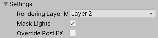
Although Unity's RPs don't do this, it's also possible to mask lights per camera, besides geometry. We'll again use rendering layers for this, but because it's nonstandard behavior let's make it optional by adding a toggle for it to CameraSettings.
public bool maskLights = false;
All we need to do to make this work is skip masked lights in Lighting.SetupLights. Add a rendering layer mask parameter to the method for this, then check whether each light's rendering layer mask overlaps the provided mask. If so proceed to the switch statement to set up the light, otherwise skip it.
	void SetupLights (bool useLightsPerObject, int renderingLayerMask) {
		…
		for (i = 0; i < visibleLights.Length; i++) {
			int newIndex = -1;
			VisibleLight visibleLight = visibleLights[i];
			Light light = visibleLight.light;
			if ((light.renderingLayerMask & renderingLayerMask) != 0) {
				switch (visibleLight.lightType) {
					…
				}
			}
			if (useLightsPerObject) {
				indexMap[i] = newIndex;
			}
		}

		…
	}
Lighting.Setup must pass the rendering layer mask along.
	public void Setup (
		ScriptableRenderContext context, CullingResults cullingResults,
		ShadowSettings shadowSettings, bool useLightsPerObject, int renderingLayerMask
	) {
		…
		SetupLights(useLightsPerObject, renderingLayerMask);
		…
	}
And we have to provide the camera's mask in CameraRenderer.Render, but only if it applies to lights, otherwise use −1.
		lighting.Setup(
			context, cullingResults, shadowSettings, useLightsPerObject,
			cameraSettings.maskLights ? cameraSettings.renderingLayerMask : -1
		);
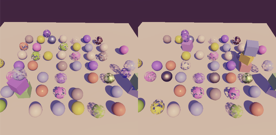
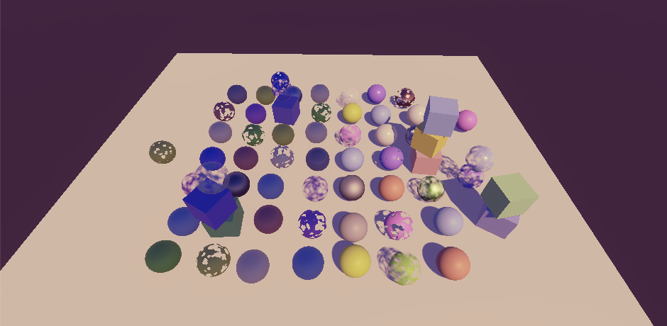
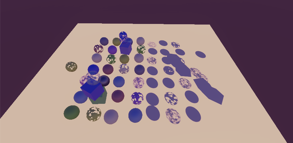
Now we can do things like have two cameras render the same scene, but with different lighting, without having to adjust the lights in between. This also makes it easy to render a separate scene like a character portrait at the world origin without having lighting from the main scene affect it. Note that this only applies to realtime lighting, fully baked light and the baked indirect contribution of mixed lights cannot be masked.
The next tutorial is Particles.