Marching Squares 5
Being Colorful
- Support more than two colors.
- Keep normals consistent.
- Distribute work among multiple structs and objects.
- Find a new way to triangulate.
- Deal with shared feature points.
- Make nice circles.
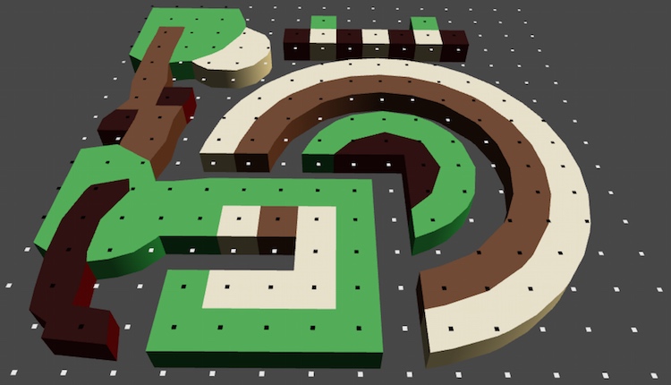
In this tutorial we'll add support for multiple colors to Marching Squares.
This tutorial comes after Marching Squares 4. Like the previous ones, it has been made with Unity 4.5.2 and might not work for older versions.
Adding More Choices
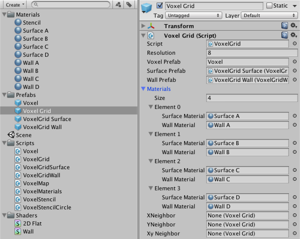
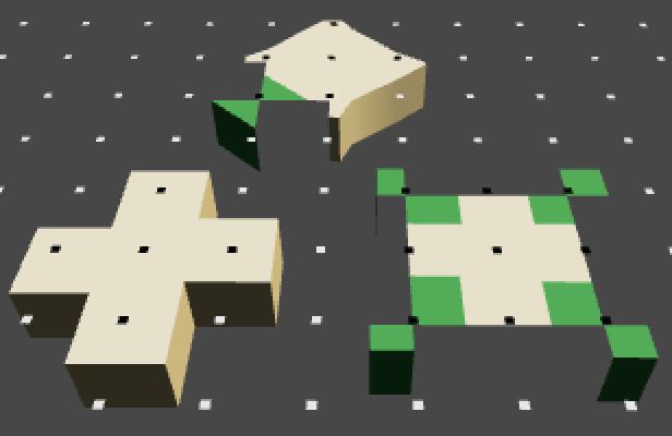
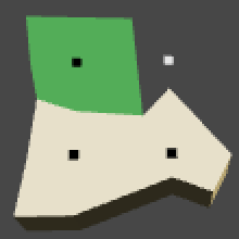
While using only two voxel states – empty and filled – already allows for complex and interesting shapes, allowing even more states would greatly enhance our expressiveness. Once we're able to deal with four different states we could support as many as we want, because each individual cell can contain up to four unique states.
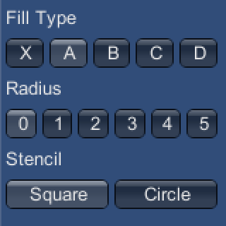
Let's start at the top with the UI and add more fill type options to VoxelMap. We need at least four but I'll make it five, the empty state and four filled ones. I'll label them with letters, naming the empty state X and placing it on the left side. That way the first index – voxel state zero – represents emptiness.
private static string[] fillTypeNames = {"X", "A", "B", "C", "D"};
Because starting with the eraser selected doesn't make much sense, you can set the default type selection to the first filled state, which would be A.
private int fillTypeIndex = 1, radiusIndex, stencilIndex;
In OnGUI, put all five type buttons on a single line.
	fillTypeIndex =
			GUILayout.SelectionGrid(fillTypeIndex, fillTypeNames, 5);
In EditVoxels, we used to pass a boolean fill type, but now we should pass the index itself.
	activeStencil.Initialize(
			fillTypeIndex, (radiusIndex + 0.5f) * voxelSize);
Of course we now get compile errors because of a type mismatch, which means that we'll have to adjust VoxelStencil next.
Upgrading the Stencils
The fill type of VoxelStencil needs to become an integer.
protected int fillType;
Adjust the parameter type of Initialize as well, both in VoxelStencil and VoxelStencilCircle.
… void Initialize (int fillType, float radius) …
More compiler errors show up. For now just change the state type in Voxel, then ignore the errors produced in the grid.
public int state;
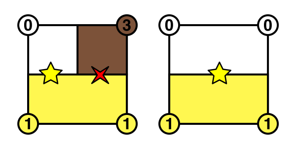
Back to VoxelStencil. When finding a crossing, the fill type is used to determine which way the normal should point. But what way to point the edge normal between two filled sides? Although we won't need normals for a wall there, we do need then to detect sharp features. The most important thing here is consistency. Let them always point toward the side with the lowest index. That way the normals are guaranteed to be correctly oriented at the boundary between filled and empty space.
	protected virtual void FindHorizontalCrossing (Voxel xMin, Voxel xMax) {
		if (xMin.position.y < YStart || xMin.position.y > YEnd) {
			return;
		}
		if (xMin.state == fillType) {
			if (xMin.position.x <= XEnd && xMax.position.x >= XEnd) {
				if (xMin.xEdge == float.MinValue || xMin.xEdge < XEnd) {
					xMin.xEdge = XEnd;
					xMin.xNormal =
						new Vector2(fillType > xMax.state ? 1f : -1f, 0f);
				}
			}
		}
		else if (xMax.state == fillType) {
			if (xMin.position.x <= XStart && xMax.position.x >= XStart) {
				if (xMin.xEdge == float.MinValue || xMin.xEdge > XStart) {
					xMin.xEdge = XStart;
					xMin.xNormal =
						new Vector2(fillType > xMin.state ? -1f : 1f, 0f);
				}
			}
		}
	}
However, this only works when there wasn't a crossing before or if we're moving beyond an existing one. What to do when cutting behind another edge? Realistically that would leave a fragment of the old material behind, but we cannot store this information so have to discard it. Once again let's simply be consistent and leave the edge where it is, effectively extending the range of our edit.
We still have to make sure that the normal points in the right direction. Let's add a validation method which flips the normal when it's pointing in the wrong direction. First for horizontal crossings.
	protected virtual void FindHorizontalCrossing (Voxel xMin, Voxel xMax) {
		if (xMin.position.y < YStart || xMin.position.y > YEnd) {
			return;
		}
		if (xMin.state == fillType) {
			if (xMin.position.x <= XEnd && xMax.position.x >= XEnd) {
				if (xMin.xEdge == float.MinValue || xMin.xEdge & XEnd) {
					xMin.xEdge = XEnd;
					xMin.xNormal =
						new Vector2(fillType > xMax.state ? 1f : -1f, 0f);
				}
				else {
					ValidateHorizontalNormal(xMin, xMax);
				}
			}
		}
		else if (xMax.state == fillType) {
			if (xMin.position.x <= XStart && xMax.position.x >= XStart) {
				if (xMin.xEdge == float.MinValue || xMin.xEdge > XStart) {
					xMin.xEdge = XStart;
					xMin.xNormal =
						new Vector2(fillType > xMin.state ? -1f : 1f, 0f);
				}
				else {
					ValidateHorizontalNormal(xMin, xMax);
				}
			}
		}
	}

	protected static void ValidateHorizontalNormal (Voxel xMin, Voxel xMax) {
		if (xMin.state < xMax.state) {
			if (xMin.xNormal.x > 0f) {
				xMin.xNormal = -xMin.xNormal;
			}
		}
		else if (xMin.xNormal.x < 0f) {
			xMin.xNormal = -xMin.xNormal;
		}
	}
And the same for the vertical crossings.
	protected virtual void FindVerticalCrossing (Voxel yMin, Voxel yMax) {
		if (yMin.position.x < XStart || yMin.position.x > XEnd) {
			return;
		}
		if (yMin.state == fillType) {
			if (yMin.position.y <= YEnd && yMax.position.y >= YEnd) {
				if (yMin.yEdge == float.MinValue || yMin.yEdge < YEnd) {
					yMin.yEdge = YEnd;
					yMin.yNormal =
						new Vector2(0f, fillType > yMax.state ? 1f : -1f);
				}
				else {
					ValidateVerticalNormal(yMin, yMax);
				}
			}
		}
		else if (yMax.state == fillType) {
			if (yMin.position.y <= YStart && yMax.position.y >= YStart) {
				if (yMin.yEdge == float.MinValue || yMin.yEdge > YStart) {
					yMin.yEdge = YStart;
					yMin.yNormal =
						new Vector2(0f, fillType > yMin.state ? -1f : 1f);
				}
				else {
					ValidateVerticalNormal(yMin, yMax);
				}
			}
		}
	}

	protected static void ValidateVerticalNormal (Voxel yMin, Voxel yMax) {
		if (yMin.state < yMax.state) {
			if (yMin.yNormal.y > 0f) {
				yMin.yNormal = -yMin.yNormal;
			}
		}
		else if (yMin.yNormal.y < 0f) {
			yMin.yNormal = -yMin.yNormal;
		}
	}
VoxelStencilCircle needs to receive the same treatment. As it uses a separate ComputeNormal method to find the normal, let's just pass the other voxel to that method and have it compare the states.
	private Vector3 ComputeNormal (float x, float y, Voxel other) {
		if (fillType > other.state) {
			return new Vector2(x - centerX, y - centerY).normalized;
		}
		else {
			return new Vector2(centerX - x, centerY - y).normalized;
		}
	}
Then adjust the crossing methods.
protected override void FindHorizontalCrossing (Voxel xMin, Voxel xMax) {
		float y2 = xMin.position.y - centerY;
		y2 *= y2;
		if (xMin.state == fillType) {
			float x = xMin.position.x - centerX;
			if (x * x + y2 <= sqrRadius) {
				x = centerX + Mathf.Sqrt(sqrRadius - y2);
				if (xMin.xEdge == float.MinValue || xMin.xEdge < x) {
					xMin.xEdge = x;
					xMin.xNormal = ComputeNormal(x, xMin.position.y, xMax);
				}
				else {
					ValidateHorizontalNormal(xMin, xMax);
				}
			}
		}
		else if (xMax.state == fillType) {
			float x = xMax.position.x - centerX;
			if (x * x + y2 <= sqrRadius) {
				x = centerX - Mathf.Sqrt(sqrRadius - y2);
				if (xMin.xEdge == float.MinValue || xMin.xEdge > x) {
					xMin.xEdge = x;
					xMin.xNormal = ComputeNormal(x, xMin.position.y, xMin);
				}
				else {
					ValidateHorizontalNormal(xMin, xMax);
				}
			}
		}
	}

	protected override void FindVerticalCrossing (Voxel yMin, Voxel yMax) {
		float x2 = yMin.position.x - centerX;
		x2 *= x2;
		if (yMin.state == fillType) {
			float y = yMin.position.y - centerY;
			if (y * y + x2 <= sqrRadius) {
				y = centerY + Mathf.Sqrt(sqrRadius - x2);
				if (yMin.yEdge == float.MinValue || yMin.yEdge < y) {
					yMin.yEdge = y;
					yMin.yNormal = ComputeNormal(yMin.position.x, y, yMax);
				}
				else {
					ValidateVerticalNormal(yMin, yMax);
				}
			}
		}
		else if (yMax.state == fillType) {
			float y = yMax.position.y - centerY;
			if (y * y + x2 <= sqrRadius) {
				y = centerY - Mathf.Sqrt(sqrRadius - x2);
				if (yMin.yEdge == float.MinValue || yMin.yEdge > y) {
					yMin.yEdge = y;
					yMin.yNormal = ComputeNormal(yMin.position.x, y, yMin);
				}
				else {
					ValidateVerticalNormal(yMin, yMax);
				}
			}
		}
	}
unitypackage
Working with Different Voxel Visualizations
The quick way to fix the errors in VoxelGrid is to replace all seven test for voxel.state with voxel.Filled. Then we can paint again and actually mix different voxel types, though we won't see different colors yet. Of course we need to add that handy property to Voxel to make it work.
	public bool Filled {
		get {
			return state > 0f;
		}
	}
We need materials to visualize the different states. Each filled state should have its own surface material and wall material. We can add two material arrays to VoxelGrid to hold them. Alternatively, we could add a single array of pairs of these materials, which fits the relationship between the materials better. To do so, we need to define a simple structure for the pairs.
using UnityEngine;
using System;

[Serializable]
public struct VoxelMaterials {

	public Material surfaceMaterial, wallMaterial;
}
Now we can add an array of those to VoxelGrid.
public VoxelMaterials[] materials;
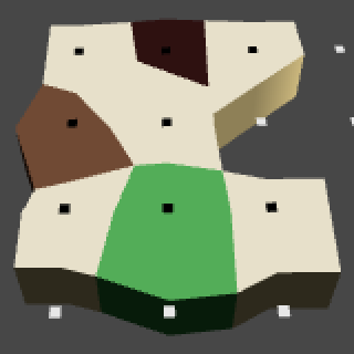
Then create three more pairs of materials. That gives us a total of four pairs, as the empty state doesn't need materials. Use whatever colors you like. I tidied up the project a bit too.
Both VoxelGridSurface and VoxelGridWall now need to be initialized with a material.
	public void Initialize (int resolution, Material material) {
		GetComponent<MeshRenderer>().material = material;
		…
	}
Because managing all the different meshes is becoming more complex, let's create a MeshRenderer structure to encapsulate surface–wall pairs, just like for the materials.
using UnityEngine;
using System;

[Serializable]
public struct VoxelRenderer {

	[SerializeField]
	private VoxelGridSurface surface;

	[SerializeField]
	private VoxelGridWall wall;

	public VoxelRenderer (VoxelGridSurface surface, VoxelGridWall wall) {
		this.surface = surface;
		this.wall = wall;
	}
}
Now VoxelGrid can use a single array of those instead of having to worry about separate surfaces and walls.
private VoxelRenderer[] renderers;
Create the renderers when initializing VoxelGrid. Use the amount of materials to determine how many different visualizations we need. Instantiate the prefabs as normal, initialize them with the correct materials, and put them into a new renderer.
Actually, create one more renderers than needed, and then skip the first one during initialization. This way we can use the voxel state to directly index the renderers array, instead of having to subtract one from it each time.
	public void Initialize (int resolution, float size, float maxFeatureAngle) {
		…

		for (int i = 0, y = 0; y < resolution; y++) {
			for (int x = 0; x < resolution; x++, i++) {
				CreateVoxel(i, x, y);
			}
		}

		CreateRenderers();
		Refresh();
	}

	private void CreateRenderers () {
		renderers = new VoxelRenderer[materials.Length + 1];
		for (int i = 0; i < materials.Length; i++) {
			VoxelGridSurface surface =
				Instantiate(surfacePrefab) as VoxelGridSurface;
			surface.transform.parent = transform;
			surface.transform.localPosition = Vector3.zero;
			surface.Initialize(resolution, materials[i].surfaceMaterial);

			VoxelGridWall wall = Instantiate(wallPrefab) as VoxelGridWall;
			wall.transform.parent = transform;
			wall.transform.localPosition = Vector3.zero;
			wall.Initialize(resolution, materials[i].wallMaterial);

			renderers[i + 1] = new VoxelRenderer(s, w);
		}
	}
After initialization the grid now only works with the renderers and will no longer directly access the surfaces and walls. This means that VoxelRenderer now has to accept caching commands and forward them to its surface and wall. So we have to give it some methods to support this.
	public void Clear () {
		surface.Clear();
		wall.Clear();
	}

	public void Apply () {
		surface.Apply();
		wall.Apply();
	}

	public void PrepareCacheForNextCell () {
		surface.PrepareCacheForNextCell();
		wall.PrepareCacheForNextCell();
	}

	public void PrepareCacheForNextRow () {
		surface.PrepareCacheForNextRow();
		wall.PrepareCacheForNextRow();
	}

	public void CacheFirstCorner (Voxel voxel) {
		surface.CacheFirstCorner(voxel);
	}

	public void CacheNextCorner (int i, Voxel voxel) {
		surface.CacheNextCorner(i, voxel);
	}

	public void CacheXEdge (int i, Voxel voxel) {
		surface.CacheXEdge(i, voxel);
	}

	public void CacheXEdgeWithWall (int i, Voxel voxel) {
		surface.CacheXEdge(i, voxel);
		wall.CacheXEdge(i, voxel);
	}

	public void CacheYEdge (Voxel voxel) {
		surface.CacheYEdge(voxel);
	}

	public void CacheYEdgeWithWall (Voxel voxel) {
		surface.CacheYEdge(voxel);
		wall.CacheYEdge(voxel);
	}
Now VoxelGrid has to invoke these methods instead of the old ones. First, all renderers for non-empty states need to be cleared and applied.
	private void Triangulate () {
		for (int i = 1; i < renderers.Length; i++) {
			renderers[i].Clear();
		}
		FillFirstRowCache();
		TriangulateCellRows();
		if (yNeighbor != null) {
			TriangulateGapRow();
		}
		for (int i = 1; i < renderers.Length; i++) {
			renderers[i].Apply();
		}
	}
Caching needs to access the correct renderer, which we made possibly by simply indexing the array using the voxel state. The first corner is easy.
	private void CacheFirstCorner (Voxel voxel) {
		if (voxel.Filled) {
			renderers[voxel.state].CacheFirstCorner(voxel);
		}
	}
The next corner and edge also needs to determine which renderers to use, and whether there's a wall or a second renderer involved.
	private void CacheNextEdgeAndCorner (int i, Voxel xMin, Voxel xMax) {
		if (xMin.state != xMax.state) {
			if (xMin.Filled) {
				if (xMax.Filled) {
					renderers[xMin.state].CacheXEdge(i, xMin);
					renderers[xMax.state].CacheXEdge(i, xMin);
				}
				else {
					renderers[xMin.state].CacheXEdgeWithWall(i, xMin);
				}
			}
			else {
				renderers[xMax.state].CacheXEdgeWithWall(i, xMin);
			}
		}
		if (xMax.Filled) {
			renderers[xMax.state].CacheNextCorner(i, xMax);
		}
	}
The next middle edge has the same questions to ask. It also needs to prepare all renderers for the next cell.
	private void CacheNextMiddleEdge (Voxel yMin, Voxel yMax) {
		for (int i = 1; i < renderers.Length; i++) {
			renderers[i].PrepareCacheForNextCell();
		}
		if (yMin.state != yMax.state) {
			if (yMin.Filled) {
				if (yMax.Filled) {
					renderers[yMin.state].CacheYEdge(yMin);
					renderers[yMax.state].CacheYEdge(yMin);
				}
				else {
					renderers[yMin.state].CacheYEdgeWithWall(yMin);
				}
			}
			else {
				renderers[yMax.state].CacheYEdgeWithWall(yMin);
			}
		}
	}
And finally the row caches need to be swapped.
	private void SwapRowCaches () {
		for (int i = 1; i < renderers.Length; i++) {
			renderers[i].PrepareCacheForNextRow();
		}
	}
Now remove the surface and wall variable declarations. This causes compile errors in all triangulations method, but they are no longer valid anyway. You can remove or comment out all that code.
Formalizing a Cell
We often talk about cells, but we don't have a cell entity. Instead of constantly passing sets of voxels around, let's create a cell object that stores four voxels. It is also the natural place for any method that analyzes the contents of a cells, so let's store the sharp feature limit in it too.
using UnityEngine;
using System;

[Serializable]
public class VoxelCell {

	[NonSerialized]
	public Voxel a, b, c, d;

	[NonSerialized]
	public int i;

	public float sharpFeatureLimit;
}
It's simply a convenient data package that we add to VoxelGrid as a private variable. This way we no longer need to move all this data around all the time.
	private VoxelCell cell = new VoxelCell();

	public void Initialize (int resolution, float size, float maxFeatureAngle) {
		cell.sharpFeatureLimit = Mathf.Cos(maxFeatureAngle * Mathf.Deg2Rad);
		…
	}
Now we can put all code about finding sharp features into the cell. Ideally these are simply properties that give us a desired feature point, or nothing if it doesn't exist. To facilitate this, create a feature point struct that contains both its position and whether it actually exists.
using UnityEngine;

public struct FeaturePoint {

	public Vector2 position;

	public bool exists;
}
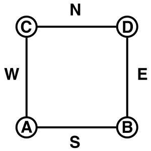
Now we can add convenient properties to VoxelCell. Let's also label the four edges using compass directions, as W is easier to read than AC and so on.
	public FeaturePoint FeatureSW {
		get {
			return GetSharpFeature(
				a.XEdgePoint, a.xNormal, a.YEdgePoint, a.yNormal);
		}
	}

	public FeaturePoint FeatureSE {
		get {
			return GetSharpFeature(
				a.XEdgePoint, a.xNormal, b.YEdgePoint, b.yNormal);
		}
	}

	public FeaturePoint FeatureNW {
		get {
			return GetSharpFeature(
				a.YEdgePoint, a.yNormal, c.XEdgePoint, c.xNormal);
		}
	}

	public FeaturePoint FeatureNE {
		get {
			return GetSharpFeature(
				c.XEdgePoint, c.xNormal, b.YEdgePoint, b.yNormal);
		}
	}

	public FeaturePoint FeatureNS {
		get {
			return GetSharpFeature(
				a.XEdgePoint, a.xNormal, c.XEdgePoint, c.xNormal);
		}
	}

	public FeaturePoint FeatureEW {
		get {
			return GetSharpFeature(
				a.YEdgePoint, a.yNormal, b.YEdgePoint, b.yNormal);
		}
	}
As these properties have to decide whether a feature point exists without any context, we cannot know whether it's fine to clamp them or not. So we simply won't. A feature exist if it's sharp enough and lies inside the cell, otherwise it doesn't. This sacrifices some of the fidelity of our visualization, but simplifies our code.
	private FeaturePoint GetSharpFeature (
		Vector2 p1, Vector2 n1, Vector2 p2, Vector2 n2) {

		FeaturePoint point;
		if (IsSharpFeature(n1, n2)) {
			point.position = GetIntersection(p1, n1, p2, n2);
			point.exists = Contains(point.position);
		}
		else {
			point.position = Vector2.zero;
			point.exists = false;
		}
		return point;
	}
The three methods used here are the same that were previously in VoxelGrid, just moved to VoxelCell.
	private bool IsSharpFeature (Vector2 n1, Vector2 n2) {
		float dot = Vector2.Dot(n1, -n2);
		return dot >= sharpFeatureLimit && dot < 0.9999f;
	}

	private static Vector2 GetIntersection (
		Vector2 p1, Vector2 n1, Vector2 p2, Vector2 n2) {

		Vector2 d2 = new Vector2(-n2.y, n2.x);
		float u2 = -Vector2.Dot(n1, p2 - p1) / Vector2.Dot(n1, d2);
		return p2 + d2 * u2;
	}

	private bool IsInsideCell (Vector2 point) {
		return
			point.x > a.position.x && amp;point.y > a.position.y &&
				point.x < d.position.x && point.y < d.position.y;
	}
unitypackage
Filling Cells
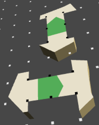
Rendering cells with triangles is now the job of the renderers. VoxelGrid still figures out the topology of a cell, then leaves it up to the renderers to fill the cell with walls and surfaces.
When working through the topology of a cell, ideally we no longer care whether a certain state is empty or filled. It's convenient to just invoke a filling method for any state. These fill methods then check whether the state is actually filled, and if so forward the request to the appropriate renderer. Otherwise it simply does nothing. Here's such a method for filling an isolated A corner.
	private void FillA (FeaturePoint f) {
		if (cell.a.Filled) {
			renderers[cell.a.state].FillA(cell, f);
		}
	}
Passing the cell to VoxelRenderer allows it to figure out whether it needs to place walls. In case of a sharp feature each side needs to be checked separately, because they could have different voxel states. If there is no feature, then both adjacent voxels should have the same state and these separate checks are not needed.
	public void FillA (VoxelCell cell, FeaturePoint f) {
		if (f.exists) {
			surface.AddQuadA(cell.i, f.position);
			if (!cell.c.Filled) {
				wall.AddFromAC(cell.i, f.position);
			}
			if (!cell.b.Filled) {
				wall.AddToAB(cell.i, f.position);
			}
		}
		else {
			surface.AddTriangleA(cell.i);
			if (!cell.b.Filled) {
				wall.AddACAB(cell.i);
			}
		}
	}
This means that VoxelGridWall need to support adding sections that go from an edge to a feature point, or from a feature point to an edge. Half sections, if you will.
	public void AddFromAB (int i, Vector2 extraVertex) {
		AddHalfSection(xEdgesMin[i], extraVertex);
	}

	public void AddToAB (int i, Vector2 extraVertex) {
		AddHalfSection(extraVertex, xEdgesMin[i]);
	}

	public void AddFromAC (int i, Vector2 extraVertex) {
		AddHalfSection(yEdgeMin, extraVertex);
	}

	public void AddToAC (int i, Vector2 extraVertex) {
		AddHalfSection(extraVertex, yEdgeMin);
	}

	public void AddFromBD (int i, Vector2 extraVertex) {
		AddHalfSection(yEdgeMax, extraVertex);
	}

	public void AddToBD (int i, Vector2 extraVertex) {
		AddHalfSection(extraVertex, yEdgeMax);
	}

	public void AddFromCD (int i, Vector2 extraVertex) {
		AddHalfSection(xEdgesMax[i], extraVertex);
	}

	public void AddToCD (int i, Vector2 extraVertex) {
		AddHalfSection(extraVertex, xEdgesMax[i]);
	}
This assumes the existence of two AddHalfSection methods, so add those as well. While we're at it, we can extract the code that constructs a feature point and put that in its own method so we can reuse it.
	private void AddSection (int a, int b, Vector3 extraPoint) {
		AddSection(a, AddPoint(extraPoint, a));
		AddSection(AddPoint(extraPoint, b), b);
	}

	private void AddHalfSection (int a, Vector3 extraPoint) {
		AddSection(a, AddPoint(extraPoint, a));
	}

	private void AddHalfSection (Vector3 extraPoint, int a) {
		AddSection(AddPoint(extraPoint, a), a);
	}

	private int AddPoint (Vector3 extraPoint, int normalIndex) {
		int p = vertices.Count;
		extraPoint.z = bottom;
		vertices.Add(extraPoint);
		extraPoint.z = top;
		vertices.Add(extraPoint);
		Vector3 n = normals[normalIndex];
		normals.Add(n);
		normals.Add(n);
		return p;
	}
Let's go ahead and create all the other fill methods too. I won't bother showing the methods for VoxelGrid, as they all have the same simple structure as FillA. Check if the relevant voxel is filled, if so index the renderers array and invoke the method with the same name.
On to VoxelRenderer! The other three single-corner methods are slight variations of FillA. I marked the differences.
public void FillB (VoxelCell cell, FeaturePoint f) {
		if (f.exists) {
			surface.AddQuadB(cell.i, f.position);
			if (!cell.a.Filled) {
				wall.AddFromAB(cell.i, f.position);
			}
			if (!cell.d.Filled) {
				wall.AddToBD(cell.i, f.position);
			}
		}
		else {
			surface.AddTriangleB(cell.i);
			if (!cell.a.Filled) {
				wall.AddABBD(cell.i);
			}
		}
	}

	public void FillC (VoxelCell cell, FeaturePoint f) {
		if (f.exists) {
			surface.AddQuadC(cell.i, f.position);
			if (!cell.d.Filled) {
				wall.AddFromCD(cell.i, f.position);
			}
			if (!cell.a.Filled) {
				wall.AddToAC(cell.i, f.position);
			}
		}
		else {
			surface.AddTriangleC(cell.i);
			if (!cell.a.Filled) {
				wall.AddCDAC(cell.i);
			}
		}
	}

	public void FillD (VoxelCell cell, FeaturePoint f) {
		if (f.exists) {
			surface.AddQuadD(cell.i, f.position);
			if (!cell.b.Filled) {
				wall.AddFromBD(cell.i, f.position);
			}
			if (!cell.c.Filled) {
				wall.AddToCD(cell.i, f.position);
			}
		}
		else {
			surface.AddTriangleD(cell.i);
			if (!cell.b.Filled) {
				wall.AddBDCD(cell.i);
			}
		}
	}
Next up are the methods that fill all but one corner. These are simpler because there's only one adjacent state to check. Here's FillABC.
	public void FillABC (VoxelCell cell, FeaturePoint f) {
		if (f.exists) {
			surface.AddHexagonABC(cell.i, f.position);
			if (!cell.d.Filled) {
				wall.AddCDBD(cell.i, f.position);
			}
		}
		else {
			surface.AddPentagonABC(cell.i);
			if (!cell.d.Filled) {
				wall.AddCDBD(cell.i);
			}
		}
	}
And in the same vein for FillABD, FillACD, and FillBCD.
	public void FillABD (VoxelCell cell, FeaturePoint f) {
		if (f.exists) {
			surface.AddHexagonABD(cell.i, f.position);
			if (!cell.c.Filled) {
				wall.AddACCD(cell.i, f.position);
			}
		}
		else {
			surface.AddPentagonABD(cell.i);
			if (!cell.c.Filled) {
				wall.AddACCD(cell.i);
			}
		}
	}

	public void FillACD (VoxelCell cell, FeaturePoint f) {
		if (f.exists) {
			surface.AddHexagonACD(cell.i, f.position);
			if (!cell.b.Filled) {
				wall.AddBDAB(cell.i, f.position);
			}
		}
		else {
			surface.AddPentagonACD(cell.i);
			if (!cell.b.Filled) {
				wall.AddBDAB(cell.i);
			}
		}
	}

	public void FillBCD (VoxelCell cell, FeaturePoint f) {
		if (f.exists) {
			surface.AddHexagonBCD(cell.i, f.position);
			if (!cell.a.Filled) {
				wall.AddABAC(cell.i, f.position);
			}
		}
		else {
			surface.AddPentagonBCD(cell.i);
			if (!cell.a.Filled) {
				wall.AddABAC(cell.i);
			}
		}
	}
Then straight across a cell. We once again have to check twice whether to place a wall when there's a feature. Here's FillAB.
	public void FillAB (VoxelCell cell, FeaturePoint f) {
		if (f.exists) {
			surface.AddPentagonAB(cell.i, f.position);
			if (!cell.c.Filled) {
				wall.AddFromAC(cell.i, f.position);
			}
			if (!cell.d.Filled) {
				wall.AddToBD(cell.i, f.position);
			}
		}
		else {
			surface.AddQuadAB(cell.i);
			if (!cell.c.Filled) {
				wall.AddACBD(cell.i);
			}
		}
	}
And the same for FillAC, FillBD, and FillCD.
public void FillAC (VoxelCell cell, FeaturePoint f) {
		if (f.exists) {
			surface.AddPentagonAC(cell.i, f.position);
			if (!cell.d.Filled) {
				wall.AddFromCD(cell.i, f.position);
			}
			if (!cell.b.Filled) {
				wall.AddToAB(cell.i, f.position);
			}
		}
		else {
			surface.AddQuadAC(cell.i);
			if (!cell.b.Filled) {
				wall.AddCDAB(cell.i);
			}
		}
	}

	public void FillBD (VoxelCell cell, FeaturePoint f) {
		if (f.exists) {
			surface.AddPentagonBD(cell.i, f.position);
			if (!cell.a.Filled) {
				wall.AddFromAB(cell.i, f.position);
			}
			if (!cell.c.Filled) {
				wall.AddToCD(cell.i, f.position);
			}
		}
		else {
			surface.AddQuadBD(cell.i);
			if (!cell.a.Filled) {
				wall.AddABCD(cell.i);
			}
		}
	}

	public void FillCD (VoxelCell cell, FeaturePoint f) {
		if (f.exists) {
			surface.AddPentagonCD(cell.i, f.position);
			if (!cell.b.Filled) {
				wall.AddFromBD(cell.i, f.position);
			}
			if (!cell.a.Filled) {
				wall.AddToAC(cell.i, f.position);
			}
		}
		else {
			surface.AddQuadCD(cell.i);
			if (!cell.a.Filled) {
				wall.AddBDAC(cell.i);
			}
		}
	}
Then the four halves of diagonal connections. Remember that each of these work on a diagonal slice of a cell. Starting with FillADToB.
	public void FillADToB (VoxelCell cell, FeaturePoint f) {
		if (f.exists) {
			surface.AddPentagonADToB(cell.i, f.position);
			if (!cell.b.Filled) {
				wall.AddBDAB(cell.i, f.position);
			}
		}
		else {
			surface.AddQuadADToB(cell.i);
			if (!cell.b.Filled) {
				wall.AddBDAB(cell.i);
			}
		}
	}
And of course FillADToC, FillBCToA, and FillBCToD.
public void FillADToC (VoxelCell cell, FeaturePoint f) {
		if (f.exists) {
			surface.AddPentagonADToC(cell.i, f.position);
			if (!cell.c.Filled) {
				wall.AddACCD(cell.i, f.position);
			}
		}
		else {
			surface.AddQuadADToC(cell.i);
			if (!cell.c.Filled) {
				wall.AddACCD(cell.i);
			}
		}
	}

	public void FillBCToA (VoxelCell cell, FeaturePoint f) {
		if (f.exists) {
			surface.AddPentagonBCToA(cell.i, f.position);
			if (!cell.a.Filled) {
				wall.AddABAC(cell.i, f.position);
			}
		}
		else {
			surface.AddQuadBCToA(cell.i);
			if (!cell.a.Filled) {
				wall.AddABAC(cell.i);
			}
		}
	}

	public void FillBCToD (VoxelCell cell, FeaturePoint f) {
		if (f.exists) {
			surface.AddPentagonBCToD(cell.i, f.position);
			if (!cell.d.Filled) {
				wall.AddCDBD(cell.i, f.position);
			}
		}
		else {
			surface.AddQuadBCToD(cell.i);
			if (!cell.d.Filled) {
				wall.AddCDBD(cell.i);
			}
		}
	}
The last one is simply a completely filled cell, so no checks are needed.
	public void FillABCD (VoxelCell cell) {
		surface.AddQuadABCD(cell.i);
	}
unitypackage
Triangulating Anew
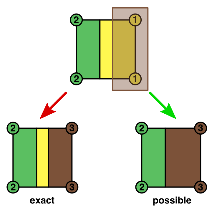
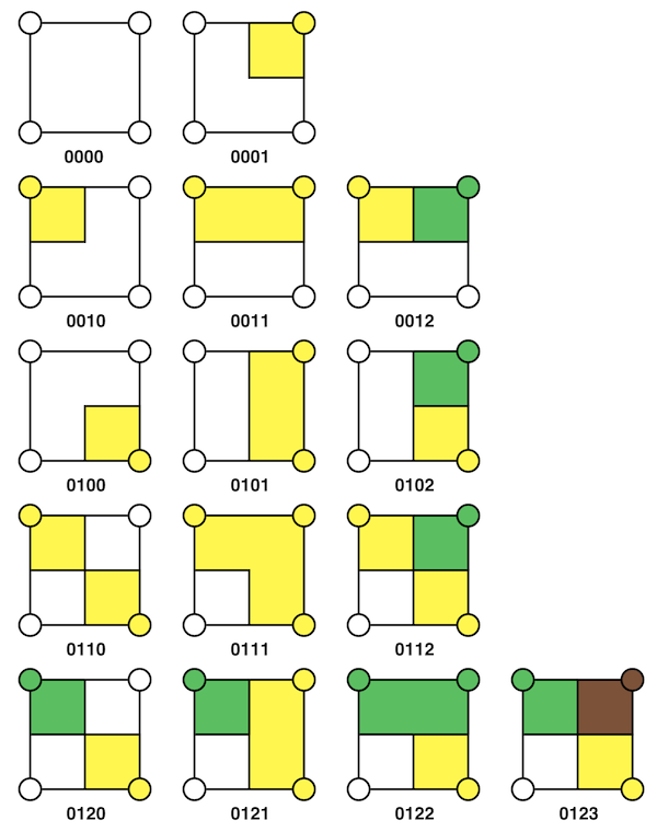
When we used only two states we had to identify sixteen different cell layouts. Now that each cell corner can have a unique state, the amount of possible combinations becomes much greater. However, if we ignore the exact colors and only concern ourselves with differences in state, we end up with only fifteen distinct possibilities.
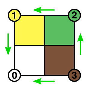
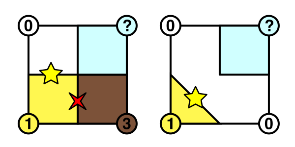
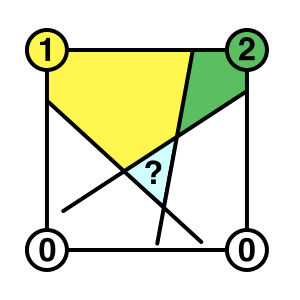
Consider corner A as our baseline. From our perspective, it is always the same. We represent it with the digit 0. Next consider corner B. If it has the same state as A, we also use 0 to describe it, otherwise we use the digit 1. We use the same approach for corners C and D, ending up with a four-digit label. The digits represent similarity, not specific material identifiers.
For example, when A, B, and D have the same state while C has a different one, we label this case with 0010, regardless what the actual states are.
Now suppose A and B have different states, while C ends up with yet another state. Then we use the digit 2 for C. And when all corners are different we need to use the digit 3 for D.
Unfortunately this means that we can no longer easily construct a number from the voxel state, we have to compare all the corners. But before we get to that, VoxelGrid.TriangulateCell should start by filling the cell with the current voxels and index.
	private void TriangulateCell (int i, Voxel a, Voxel b, Voxel c, Voxel d) {
		cell.i = i;
		cell.a = a;
		cell.b = b;
		cell.c = c;
		cell.d = d;
	}
Then onwards to comparing voxels! Let's start with case 0000, when they all have the same state. Create method stubs for the new triangulation methods as you go.
		…

		if (a.state == b.state) {
			if (a.state == c.state) {
				if (a.state == d.state) {
					Triangulate0000();
				}
			}
		}
If D turns out to be different, we have case 0001.
		if (a.state == b.state) {
			if (a.state == c.state) {
				if (a.state == d.state) {
					Triangulate0000();
				}
				else {
					Triangulate0001();
				}
			}
		}
If C turned out to be not the same as A, then D can match either A, C, or none. That leads us to cases 0010, 0011, and 0012.
		if (a.state == b.state) {
			if (a.state == c.state) {
				…
			}
			else {
				if (a.state == d.state) {
					Triangulate0010();
				}
				else if (c.state == d.state) {
					Triangulate0011();
				}
				else {
					Triangulate0012();
				}
			}
		}
Using the same logic we can arrive at all remaining cases.
		if (a.state == b.state) {
			…
		}
		else {
			if (a.state == c.state) {
				if (a.state == d.state) {
					Triangulate0100();
				}
				else if (b.state == d.state) {
					Triangulate0101();
				}
				else {
					Triangulate0102();
				}
			}
			else if (b.state == c.state) {
				if (a.state == d.state) {
					Triangulate0110();
				}
				else if (b.state == d.state) {
					Triangulate0111();
				}
				else {
					Triangulate0112();
				}
			}
			else {
				if (a.state == d.state) {
					Triangulate0120();
				}
				else if (b.state == d.state) {
					Triangulate0121();
				}
				else if (c.state == d.state) {
					Triangulate0122();
				}
				else {
					Triangulate0123();
				}
			}
		}
Let's first deal with the trivial case, 0000. Simply fill the entire cell.
	private void Triangulate0000 () {
		FillABCD();
	}
Next up are the cells with a single deviant voxel. Because we don't care about specific voxel states, these are now very easy.
	private void Triangulate0001 () {
		FeaturePoint f = cell.FeatureNE;
		FillABC(f);
		FillD(f);
	}

	private void Triangulate0010 () {
		FeaturePoint f = cell.FeatureNW;
		FillABD(f);
		FillC(f);
	}

	private void Triangulate0100 () {
		FeaturePoint f = cell.FeatureSE;
		FillACD(f);
		FillB(f);
	}

	private void Triangulate0111 () {
		FeaturePoint f = cell.FeatureSW;
		FillA(f);
		FillBCD(f);
	}
Partitioning cells in two different sections along the NS or EW lines is also simple.
	private void Triangulate0011 () {
		FeaturePoint f = cell.FeatureEW;
		FillAB(f);
		FillCD(f);
	}

	private void Triangulate0101 () {
		FeaturePoint f = cell.FeatureNS;
		FillAC(f);
		FillBD(f);
	}
These were the easy cases, the remaining ones will require some more work.
unitypackageWorking with more than Two States
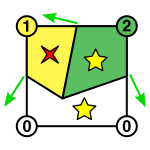
Let's now consider the cases where two adjacent corners are the same, while the remaining two are different. This means that there are three different voxel states involved. This is still simple from the point of view of VoxelGrid. Just ask the cell for the point where the three edges meet and fill the three parts.
	private void Triangulate0012 () {
		FeaturePoint f = cell.FeatureNEW;
		FillAB(f);
		FillC(f);
		FillD(f);
	}

	private void Triangulate0102 () {
		FeaturePoint f = cell.FeatureNSE;
		FillAC(f);
		FillB(f);
		FillD(f);
	}

	private void Triangulate0121 () {
		FeaturePoint f = cell.FeatureNSW;
		FillA(f);
		FillBD(f);
		FillC(f);
	}

	private void Triangulate0122 () {
		FeaturePoint f = cell.FeatureSEW;
		FillA(f);
		FillB(f);
		FillCD(f);
	}
Now it's up to VoxelCell to figure out where these points are. This could get very involved, but let's be pragmatic and simply average the feature points when considering each involved edge pair. As there must be a feature point, if we can't find one, just average the edge crossing positions.
	public FeaturePoint FeatureNEW {
		get {
			FeaturePoint f = FeaturePoint.Average(
				FeatureEW, FeatureNE, FeatureNW);
			if (!f.exists) {
				f.position = (a.YEdgePoint + b.YEdgePoint + c.XEdgePoint) / 3f;
				f.exists = true;
			}
			return f;
		}
	}

	public FeaturePoint FeatureNSE {
		get {
			FeaturePoint f = FeaturePoint.Average(
				FeatureNS, FeatureSE, FeatureNE);
			if (!f.exists) {
				f.position = (a.XEdgePoint + b.YEdgePoint + c.XEdgePoint) / 3f;
				f.exists = true;
			}
			return f;
		}
	}

	public FeaturePoint FeatureNSW {
		get {
			FeaturePoint f = FeaturePoint.Average(
				FeatureNS, FeatureNW, FeatureSW);
			if (!f.exists) {
				f.position = (a.XEdgePoint + a.YEdgePoint + c.XEdgePoint) / 3f;
				f.exists = true;
			}
			return f;
		}
	}

	public FeaturePoint FeatureSEW {
		get {
			FeaturePoint f = FeaturePoint.Average(
				FeatureEW, FeatureSE, FeatureSW);
			if (!f.exists) {
				f.position = (a.XEdgePoint + a.YEdgePoint + b.YEdgePoint) / 3f;
				f.exists = true;
			}
			return f;
		}
	}
The FeaturePoint.Average method averages the features points, but only those that actually exist. And if none exists, then neither does the average.
	public static FeaturePoint Average (
		FeaturePoint a, FeaturePoint b, FeaturePoint c) {

		FeaturePoint average;
		average.position = Vector2.zero;
		float features = 0f;
		if (a.exists) {
			average.position += a.position;
			features += 1f;
		}
		if (b.exists) {
			average.position += b.position;
			features += 1f;
		}
		if (c.exists) {
			average.position += c.position;
			features += 1f;
		}
		if (features > 0f) {
			average.position /= features;
			average.exists = true;
		}
		else {
			average.exists = false;
		}
		return average;
	}
The result of all this is that a single sharp feature will be preserved, two or three sharp features will be averaged, and if we fail to find the right point we use the crossing's average position.
However, there is something wrong with this approach. Our feature detection code expects both normals to have the same orientation. Either both point inward, or both point outward. But this will not always be the case if three different voxel states are involved.
For each feature point we need to check whether the normals are consistent, and if not flip one of them to correct this. While we could do this every time we compute a feature point, it is only really needed for the more complex feature points. So let's duplicate the unchecked public properties and turn those into private checked ones for internal usage.
	private FeaturePoint CheckedFeatureSW {
		get {
			Vector2 n2 = (a.state < b.state) == (a.state < c.state) ?
				a.yNormal : -a.yNormal;
			return GetSharpFeature(a.XEdgePoint, a.xNormal, a.YEdgePoint, n2);
		}
	}

	private FeaturePoint CheckedFeatureSE {
		get {
			Vector2 n2 = (b.state < a.state) == (b.state < c.state) ?
				b.yNormal : -b.yNormal;
			return GetSharpFeature(a.XEdgePoint, a.xNormal, b.YEdgePoint, n2);
		}
	}

	private FeaturePoint CheckedFeatureNW {
		get {
			Vector2 n2 = (c.state < a.state) == (c.state < d.state) ?
				c.xNormal : -c.xNormal;
			return GetSharpFeature(a.YEdgePoint, a.yNormal, c.XEdgePoint, n2);
		}
	}

	private FeaturePoint CheckedFeatureNE {
		get {
			Vector2 n2 = (d.state < b.state) == (d.state < c.state) ?
				b.yNormal : -b.yNormal;
			return GetSharpFeature(c.XEdgePoint, c.xNormal, b.YEdgePoint, n2);
		}
	}

	private FeaturePoint CheckedFeatureNS {
		get {
			Vector2 n2 = (a.state < b.state) == (c.state < d.state) ?
				c.xNormal : -c.xNormal;
			return GetSharpFeature(a.XEdgePoint, a.xNormal, c.XEdgePoint, n2);
		}
	}
Now use these checked properties in the triple-edge feature properties. I only show the changes to FeatureNEW.
	public FeaturePoint FeatureNEW {
		get {
			FeaturePoint f = FeaturePoint.Average(
				CheckedFeatureEW, CheckedFeatureNE, CheckedFeatureNW);
			if (!f.exists) {
				f.position = (a.YEdgePoint + b.YEdgePoint + c.XEdgePoint) / 3f;
				f.exists = true;
			}
			return f;
		}
	}
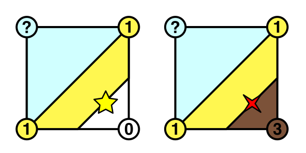
Revisiting the Ambiguous Cases
VoxelGrid.Triangulate0110 covers the diagonal cell configuration when there are exactly two different voxel states involved. Let's first only consider the AD connection. Start by requesting all feature points, then determine if there is a diagonal connection, and if so only include features that don't cross the diagonal.
	private void Triangulate0110 () {
		FeaturePoint
			fA = cell.FeatureSW, fB = cell.FeatureSE,
			fC = cell.FeatureNW, fD = cell.FeatureNE;

		if (cell.HasConnectionAD(fA, fD)) {
			fB.exists &= cell.IsInsideABD(fB.position);
			fC.exists &= cell.IsInsideACD(fC.position);
			FillADToB(fB);
			FillADToC(fC);
			FillB(fB);
			FillC(fC);
		}
	}
The logic of the new methods for VoxelCell come from the old grid, updated to take advantage of the new feature points.
	public bool HasConnectionAD (FeaturePoint fA, FeaturePoint fD) {
		if (fA.exists) {
			if (fD.exists) {
				if (IsBelowLine(fA.position, b.YEdgePoint, fD.position)) {
					if (IsBelowLine(fA.position, fD.position, c.XEdgePoint) ||
					    IsBelowLine(fD.position, fA.position, a.XEdgePoint)) {
						return true;
					}
				}
				else if (IsBelowLine(fA.position, fD.position, c.XEdgePoint) &&
				         IsBelowLine(fD.position, a.YEdgePoint, fA.position)) {
					return true;
				}
				return false;
			}
			return IsBelowLine(fA.position, b.YEdgePoint, c.XEdgePoint);
		}
		return fD.exists &&
			IsBelowLine(fD.position, a.YEdgePoint, a.XEdgePoint);
	}

	public bool IsInsideABD (Vector2 point) {
		return IsBelowLine(point, a.position, d.position);
	}

	public bool IsInsideACD (Vector2 point) {
		return IsBelowLine(point, d.position, a.position);
	}

	private static bool IsBelowLine (Vector2 p, Vector2 start, Vector2 end) {
		float determinant =
			(end.x - start.x) * (p.y - start.y) -
				(end.y - start.y) * (p.x - start.x);
		return determinant < 0f;
	}
Now to support the other diagonal as well. Adding it to VoxelGrid.Triangulate0110 is simple.
	private void Triangulate0110 () {
		FeaturePoint
			fA = cell.FeatureSW, fB = cell.FeatureSE,
			fC = cell.FeatureNW, fD = cell.FeatureNE;

		if (cell.HasConnectionAD(fA, fD)) {
			…
		}
		else if (cell.HasConnectionBC(fB, fC)) {
			fA.exists &= cell.IsInsideABC(fA.position);
			fD.exists &= cell.IsInsideBCD(fD.position);
			FillA(fA);
			FillD(fD);
			FillBCToA(fA);
			FillBCToD(fD);
		}
	}
VoxelCell has to do all the hard work.
public bool HasConnectionBC (FeaturePoint fB, FeaturePoint fC) {
		if (fB.exists) {
			if (fC.exists) {
				if (IsBelowLine(fC.position, a.XEdgePoint, fB.position)) {
					if (IsBelowLine(fC.position, fB.position, b.YEdgePoint) ||
					    IsBelowLine(fB.position, fC.position, a.YEdgePoint)) {
						return true;
					}
				}
				else if (IsBelowLine(fC.position, fB.position, b.YEdgePoint) &&
				         IsBelowLine(fB.position, c.XEdgePoint, fC.position)) {
					return true;
				}
				return false;
			}
			return IsBelowLine(fB.position, c.XEdgePoint, a.YEdgePoint);
		}
		return fC.exists &&
			IsBelowLine(fC.position, a.XEdgePoint, b.YEdgePoint);
	}

	public bool IsInsideABC (Vector2 point) {
		return IsBelowLine(point, c.position, b.position);
	}

	public bool IsInsideBCD (Vector2 point) {
		return IsBelowLine(point, b.position, c.position);
	}
What we do when we find no diagonal connection depends on whether one of the voxel states is the empty one. If all voxels are filled, then they have to share a central feature point. If one of the voxel pairs is empty, then the other two can exist independent of each other, forming an opening.
	private void Triangulate0110 () {
		FeaturePoint
			fA = cell.FeatureSW, fB = cell.FeatureSE,
			fC = cell.FeatureNW, fD = cell.FeatureNE;

		if (cell.HasConnectionAD(fA, fD)) {
			…
		}
		else if (cell.HasConnectionBC(fB, fC)) {
			…
		}
		else if (cell.a.Filled && cell.b.Filled) {
			FillJoinedCorners(fA, fB, fC, fD);
		}
		else {
			FillA(fA);
			FillB(fB);
			FillC(fC);
			FillD(fD);
		}
	}
Filling the joined corners requires averaging all four feature points. And if none exist, we have to settle for the average of the four edge crossing positions of the cell.
	private void FillJoinedCorners (
		FeaturePoint fA, FeaturePoint fB, FeaturePoint fC, FeaturePoint fD) {

		FeaturePoint point = FeaturePoint.Average(fA, fB, fC, fD);
		if (!point.exists) {
			point.position = cell.AverageNESW;
			point.exists = true;
		}
		FillA(point);
		FillB(point);
		FillC(point);
		FillD(point);
	}
This requires an additional FeaturePoint.Average method which works with four feature points instead of three. As this is a very simple change I leave it up to you to add it.
We also need a new property for VoxelCell which simply averages the four edge positions.
	public Vector2 AverageNESW {
		get {
			return (a.XEdgePoint + a.YEdgePoint +
			        b.YEdgePoint + c.XEdgePoint) * 0.25f;
		}
	}
Drawing better Circles
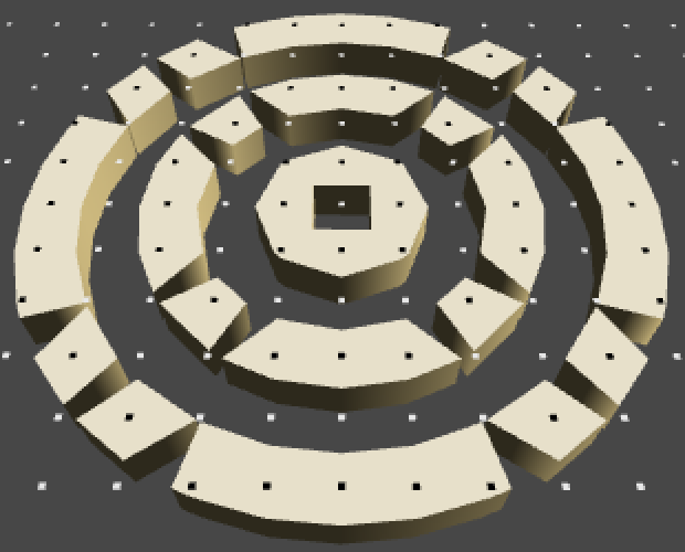
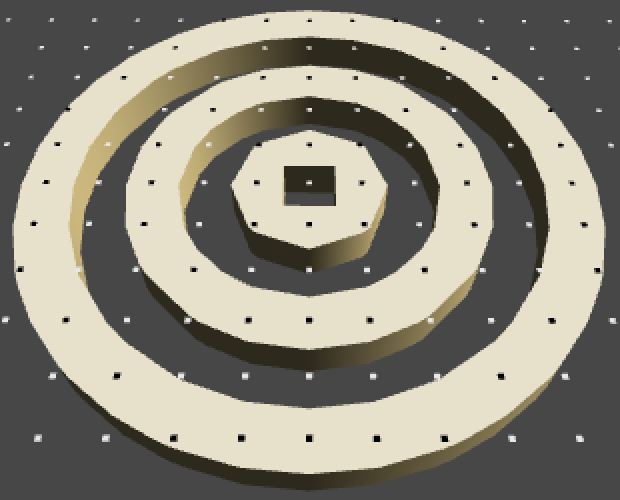
While we're working on diagonals, let's improve circles. The detection of connections formed by narrow circles fails because the edges are nearly parallel and feature points end up racing to infinity in either positive or negative direction. This wasn't so bad when we still clamped feature points, but without this trick they always fall apart.
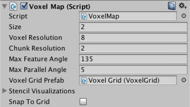
A possible solution is to add a threshold to decide whether lines are parallel. Of course we make this configurable. First add maximum angle setting to VoxelMap, with a default of five degrees.
public float maxFeatureAngle = 135f, maxParallelAngle = 5f;
Just like the maximum feature angle, we pass it to the grids when we initialize them.
	private void CreateChunk (int i, int x, int y) {
		VoxelGrid chunk = Instantiate(voxelGridPrefab) as VoxelGrid;
		chunk.Initialize(
			voxelResolution, chunkSize, maxFeatureAngle, maxParallelAngle);
		…
	}
Then VoxelGrid computes the cosine and stores it in its VoxelCell as the parallel limit.
	public void Initialize (
		int resolution, float size,
		float maxFeatureAngle, float maxParallelAngle) {

		cell.sharpFeatureLimit = Mathf.Cos(maxFeatureAngle * Mathf.Deg2Rad);
		cell.parallelLimit = Mathf.Cos(maxParallelAngle * Mathf.Deg2Rad);
		…
	}
VoxelCell can them figure out if two normals belong to parallel lines. As we perform this test for diagonal connections and those can end up with inconsistent normals, let's tell the method whether a normal should be flipped or not.
	public float sharpFeatureLimit, parallelLimit;

	private bool IsParallel (Vector2 n1, Vector2 n2, bool flip) {
		return Vector2.Dot(n1, flip ? -n2 : n2) > parallelLimit;
	}
Now we can check for a parallel connection first whenever we're asked to look for a diagonal connection.
	public bool HasConnectionAD (FeaturePoint fA, FeaturePoint fD) {
		bool flip = (a.state < b.state) == (a.state < c.state);
		if (
			IsParallel(a.xNormal, a.yNormal, flip) ||
			IsParallel(c.xNormal, b.yNormal, flip)) {
			return true;
		}
		…
	}

	public bool HasConnectionBC (FeaturePoint fB, FeaturePoint fC) {
		bool flip = (b.state < a.state) == (b.state < d.state);
		if (
			IsParallel(a.xNormal, b.yNormal, flip) ||
			IsParallel(c.xNormal, a.yNormal, flip)) {
			return true;
		}
		…
	}
Covering the Last Cases
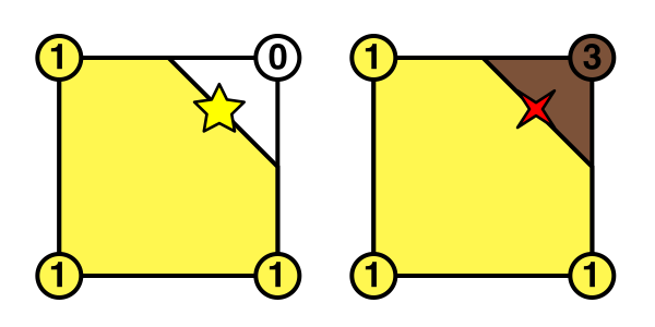
Back to VoxelGrid, cases 0112 and 0120 cover diagonals with two different voxel states on either side. Because diagonally connecting two voxels with different states doesn't really work, these methods are actually about half as complex as when only two different voxel states are involved.
	private void Triangulate0112 () {
		FeaturePoint
			fA = cell.FeatureSW, fB = cell.FeatureSE,
			fC = cell.FeatureNW, fD = cell.FeatureNE;

		if (cell.HasConnectionBC(fB, fC)) {
			fA.exists &= cell.IsInsideABC(fA.position);
			fD.exists &= cell.IsInsideBCD(fD.position);
			FillA(fA);
			FillD(fD);
			FillBCToA(fA);
			FillBCToD(fD);
		}
		else if (cell.b.Filled || cell.HasConnectionAD(fA, fD)) {
			FillJoinedCorners(fA, fB, fC, fD);
		}
		else {
			FillA(fA);
			FillD(fD);
		}
	}

	private void Triangulate0120 () {
		FeaturePoint
			fA = cell.FeatureSW, fB = cell.FeatureSE,
			fC = cell.FeatureNW, fD = cell.FeatureNE;

		if (cell.HasConnectionAD(fA, fD)) {
			fB.exists &= cell.IsInsideABD(fB.position);
			fC.exists &= cell.IsInsideACD(fC.position);
			FillADToB(fB);
			FillADToC(fC);
			FillB(fB);
			FillC(fC);
		}
		else if (cell.a.Filled || cell.HasConnectionBC(fB, fC)) {
			FillJoinedCorners(fA, fB, fC, fD);
		}
		else {
			FillB(fB);
			FillC(fC);
		}
	}
The last case is 0123, the only one that has four different voxel states in it. Fortunately this is simply another job for FillJoinedCorners.
	private void Triangulate0123 () {
		FillJoinedCorners(
			cell.FeatureSW, cell.FeatureSE,
			cell.FeatureNW, cell.FeatureNE);
	}
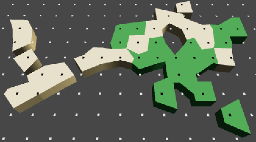
I hope you enjoyed this tutorial series about Marching Squares. There is still much more that could be covered about this subject, but a reasonable foundation has been laid. What you do with it is up to you!
unitypackage PDF