Marching Squares, partitioning space
Content creation is a big part of making games. Something special happens when editing is built right into the game itself. The player becomes a creator too.
In this tutorial you will create an editable 2D voxel grid, then use the Marching Squares algorithm to triangulate it.
You'll learn to
- Construct a 2D voxel grid;
- Split a map into chunks;
- Support editing of the voxels;
- Triangulate the voxels.
This tutorial builds on the foundation laid by previous tutorials. If you've done the Curves and Splines tutorial you should be good to go. The Noise Derivatives tutorial is also useful because it contains a basic introduction of meshes.
This tutorial has been made with Unity 4.5.2. It might not work for older versions.
Showing a Bitmap
What does it mean to edit or create something digital? Think of image editing software. Basically, you're manipulating a 2D grid of color data using various brushes, filters, and stencils. If you're using layers, you could be considered to work in three dimensions, even though the result is presented as a flat surface.
Applying this concept to games, you could be creating a level layout or world map instead of an image. Or you could even create a true 3D environment. However, there's a lot involved to get that working. Let's start with something simple.
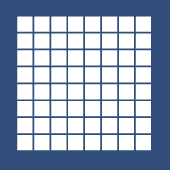
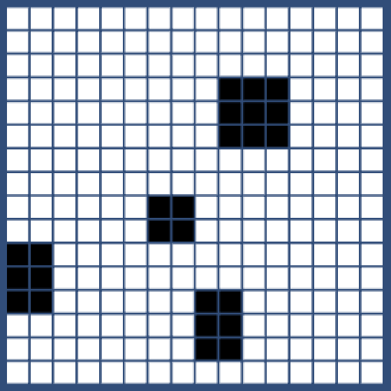
As 2D is a lot easier to work with than 3D, we'll limit ourselves to a flat surface. We'll keep it square so the width and length are the same size. We fill this square area with a voxel grid. These voxels could contain any data we want, and the simplest is a single boolean to indicate whether it's empty or filled. So for now we'll work with a grid of 1-bit values.
Creating a Voxel Grid
Create a new project. You can make it a 2D project, so you start with an orthographic camera and the scene view set to 2D mode by default. This is not essential though.
We need a custom component to contain our voxels. It needs a boolean array and a resolution. We could use a two-dimensional array, but a normal array works as well. It's both faster and makes it easier to linearly loop through all elements, in case we desire to do so.
using UnityEngine;
public class VoxelGrid : MonoBehaviour {
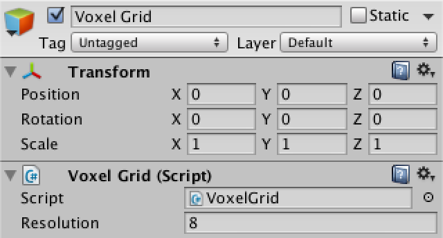
public int resolution;
private bool[] voxels;
private void Awake () {
voxels = new bool[resolution * resolution];
}
}
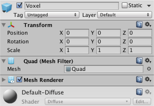
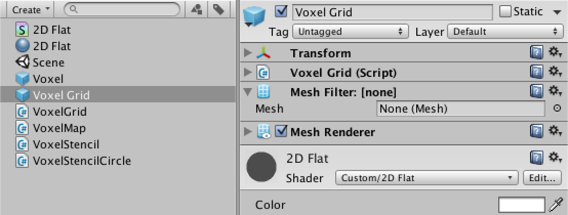
We have to use something to visualize the voxels. Let's use a default quad object, with its collider removed because we don't need that. Create one and turn it into a prefab.
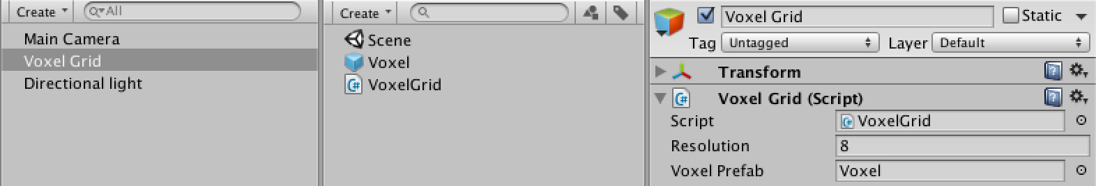
To make use of the prefab, the grid needs to get a reference to it. So add a voxelPrefab variable and drag the prefab onto it. Also add a directional light and clear its rotation, so quad instances will be fully lit.
public GameObject voxelPrefab;
For now we use a 1-unit area. So the size of the area covered by one voxel is equal to one divided by the resolution. Let's remember it.
	private float voxelSize;

	private void Awake () {
		voxelSize = 1f / resolution;
		voxels = new bool[resolution * resolution];
	}
After the array has been initialized, we can create the individual voxels. We'll loop through the X and Y direction such that our array gets filled with consecutive rows of voxels along the X axis.
		for (int i = 0, y = 0; y < resolution; y++) {
			for (int x = 0; x < resolution; x++, i++) {
				CreateVoxel(i, x, y);
			}
		}
Creating a voxel right now just requires us to instantiate, position, and scale a prefab. As the quads are centered, we set the voxel positions at the center of their area. So we have to offset by half the voxel size.
	private void CreateVoxel (int i, int x, int y) {
		GameObject o = Instantiate(voxelPrefab) as GameObject;
		o.transform.parent = transform;
		o.transform.localPosition = new Vector3((x + 0.5f) * voxelSize, (y + 0.5f) * voxelSize);
		o.transform.localScale = Vector3.one * voxelSize;
	}
Now you should see a white square show up when entering play mode, although it's actually a grid of quads. You'll probably have to adjust the orthographic camera's size property to get a good look at it.

Right now, selecting the grid of quads in the scene view selects whichever quad is under the cursor. As we'll be interested in selecting the grid as a whole, this is inconvenient. We can add the SelectionBase attribute to our component to instruct Unity to select it instead of its children.
[SelectionBase]
public class VoxelGrid : MonoBehaviour {
	…
}
Finally, to make the grid structure visible, we can reduce quad size a bit.
Vector3 voxelScale = Vector3.one * voxelSize * 0.9f;
Partitioning the Voxels
Now we have a square voxel grid, which we can make as large as we want. However, extremely large or technically infinite worlds will become a problem, especially once you start using more complex voxels and visualizations. Sooner or later, you'll have to partition your world into individual chunks to work around some technical limitation. Instead of refactoring our code once we reach that point, let's support chunking from the start. To do so, we need an overarching object that manages the individual grid chunks.
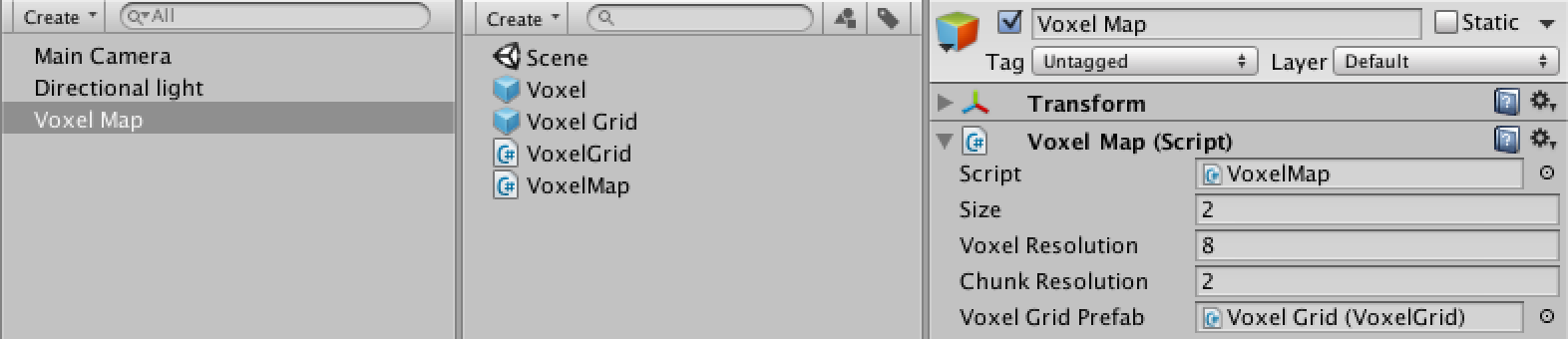
Assuming that we're working on some world or level map, we introduce a VoxelMap component. We give it a size so we can easily control to dimensions of the entire map. We also give it a voxel resolution, which we pass along to the individual voxel grids. Finally, we give it a chunk resolution, which determines the size of our chunk grid.
using UnityEngine;

public class VoxelMap : MonoBehaviour {

	public float size = 2f;

	public int voxelResolution = 8;
	public int chunkResolution = 2;

	public VoxelGrid voxelGridPrefab;
}
After adding an object with this component to the scene, turn our voxel grid into a prefab and assign it to the new map object.
As the map will create the grids and pass along their resolution and size, we turn VoxelGrid.Awake into an initialization method.
	public void Initialize (int resolution, float size) {
		this.resolution = resolution;
		voxelSize = size / resolution;
		voxels = new bool[resolution * resolution];

		for (int i = 0, y = 0; y < resolution; y++) {
			for (int x = 0; x < resolution; x++, i++) {
				CreateVoxel(i, x, y);
			}
		}
	}
VoxelMap now has to instantiate its voxel grid children when it awakens. It works similar to how voxel grids are initialized. Let's center the map around zero, so it always stays in the center of our view, no matter its size. Let's also compute and remember some convenient size values, as we might need them later.
	private VoxelGrid[] chunks;

	private float chunkSize, voxelSize, halfSize;

	private void Awake () {
		halfSize = size * 0.5f;
		chunkSize = size / chunkResolution;
		voxelSize = chunkSize / voxelResolution;

		chunks = new VoxelGrid[chunkResolution * chunkResolution];
		for (int i = 0, y = 0; y < chunkResolution; y++) {
			for (int x = 0; x < chunkResolution; x++, i++) {
				CreateChunk(i, x, y);
			}
		}
	}

	private void CreateChunk (int i, int x, int y) {
		VoxelGrid chunk = Instantiate(voxelGridPrefab) as VoxelGrid;
		chunk.Initialize(voxelResolution, chunkSize);
		chunk.transform.parent = transform;
		chunk.transform.localPosition = new Vector3(x * chunkSize - halfSize, y * chunkSize - halfSize);
		chunks[i] = chunk;
	}
Editing Voxels
To be able to edit our map, we have to detect user input. So add a 3D box collider of the appropriate size to VoxelMap when it awakens.
	private void Awake () {
		…
		BoxCollider box = gameObject.AddComponent<BoxCollider>();
		box.size = new Vector3(size, size);
	}
We'll check each update whether the mouse button is currently pressed. If so, we perform a ray-cast from the cursor position. If it hits the map, we convert the point to local space and use it to edit our voxels.
	private void Update () {
		if (Input.GetMouseButton(0)) {
			RaycastHit hitInfo;
			if(Physics.Raycast(Camera.main.ScreenPointToRay(Input.mousePosition), out hitInfo)) {
				if (hitInfo.collider.gameObject == gameObject) {
					EditVoxels(transform.InverseTransformPoint(hitInfo.point));
				}
			}
		}
	}
Before doing some real editing, let's see if we can convert the input point into voxel coordinates.
	private void EditVoxels (Vector3 point) {
		int voxelX = (int)(point.x / voxelSize);
		int voxelY = (int)(point.y / voxelSize);
		Debug.Log(voxelX + ", " + voxelY);
	}
Looks like the (0, 0) coordinate is located in the center of the map. For our finite map, it is more convenient to assign (0, 0) to the bottom left voxel, so let's offset it.
		int voxelX = (int)((point.x + halfSize) / voxelSize);
		int voxelY = (int)((point.y + halfSize) / voxelSize);
Next, we have to identify the chunk that contains the voxel.
		int voxelX = (int)((point.x + halfSize) / voxelSize);
		int voxelY = (int)((point.y + halfSize) / voxelSize);
		int chunkX = voxelX / voxelResolution;
		int chunkY = voxelY / voxelResolution;
		Debug.Log(voxelX + ", " + voxelY + " in chunk " + chunkX + ", " + chunkY);
Now that we know which voxel grid was touched we can convert to the chunk's local voxel coordinates. Then instead of logging the coordinates we instruct the chunk to fill its voxel.
		voxelX -= chunkX * voxelResolution;
		voxelY -= chunkY * voxelResolution;
		chunks[chunkY * chunkResolution + chunkX].SetVoxel(voxelX, voxelY, true);
So we have to add this method to VoxelGrid, which is simple.
	public void SetVoxel (int x, int y, bool state) {
		voxels[y * resolution + x] = state;
	}
While we are now actually editing voxels when clicking and dragging across the map, there is no visual change yet. As the voxels start empty and white, let's change the color of filled voxels to black. To do so, VoxelGrid has to know which material belongs to a voxel. A simple solution is to add a material array and fill it while we instantiate our voxel quads. Once they're all created, we can set all the voxel colors at once.
	private Material[] voxelMaterials;

	public void Initialize (int resolution, float size) {
		this.resolution = resolution;
		voxelSize = size / resolution;
		voxels = new bool[resolution * resolution];
		voxelMaterials = new Material[voxels.Length];

		for (int i = 0, y = 0; y < resolution; y++) {
			for (int x = 0; x < resolution; x++, i++) {
				CreateVoxel(i, x, y);
			}
		}
		SetVoxelColors();
	}

	private void CreateVoxel (int i, int x, int y) {
		GameObject o = Instantiate(voxelPrefab) as GameObject;
		o.transform.parent = transform;
		o.transform.localPosition = new Vector3((x + 0.5f) * voxelSize, (y + 0.5f) * voxelSize);
		o.transform.localScale = Vector3.one * voxelSize * 0.9f;
		voxelMaterials[i] = o.GetComponent<MeshRenderer>().material;
	}
Setting the voxel colors is done by simply looping through the voxels and looking at their state.
	private void SetVoxelColors () {
		for (int i = 0; i < voxels.Length; i++) {
			voxelMaterials[i].color = voxels[i] ? Color.black : Color.white;
		}
	}
By also calling SetVoxelColors after editing a voxel in SetVoxel, our edits will finally become visible.
	public void SetVoxel (int x, int y, bool state) {
		voxels[y * resolution + x] = state;
		SetVoxelColors();
	}
Stenciling
Right now we can only edit a single voxel at a time. It would be nice if we could support editing multiple voxels at once, using a stencil or brush with a configurable size. To do that, we need some kind of stencil object, so let's create a class for it. As it won't be a scene object, it won't inherit from MonoBehaviour.
Give the stencil a simple method to apply it to a voxel at a certain position. It should return the new voxel state, which for now will always be filled.
using UnityEngine;

public class VoxelStencil {

	public bool Apply (int x, int y) {
		return true;
	}
}
Now that we're applying stencils to voxels, change VoxelGrid.SetVoxel to Apply and have it accept a stencil instead of a voxel state.
	public void Apply (int x, int y, VoxelStencil stencil) {
		voxels[y * resolution + x] = stencil.Apply(x, y);
		SetVoxelColors();
	}
Now we have to create a stencil in VoxelMap.EditVoxels so we can pass it to the chunk.
		VoxelStencil activeStencil = new VoxelStencil();
		chunks[chunkY * chunkResolution + chunkX].Apply(voxelX, voxelY, activeStencil);
Changing the Paint
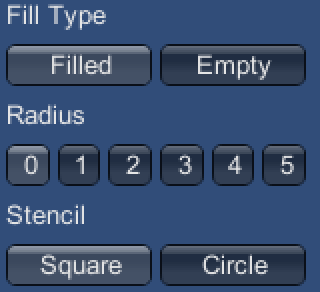
Though our approach has changed, editing still works the same from the user's or gamer's point of view. This changes once we add more features to our stencil. For example, we can set the stencil to either fill or empty the voxels it touches. To support this we add a fill type and initializer method to our stencil. Then we let Apply return this fill type.
	private bool fillType;

	public void Initialize (bool fillType) {
		this.fillType = fillType;
	}

	public bool Apply (int x, int y) {
		return fillType;
	}
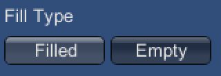
Let's add a very basic UI to switch fill type, by adding an OnGUI method to VoxelMap. Create a small layout area at the top left of the screen, then put a label and a selection grid in it. We'll use a simple string array to fill the selection grid and we'll remember which index has been selected.
	private static string[] fillTypeNames = {"Filled", "Empty"};

	private int fillTypeIndex;

	private void OnGUI () {
		GUILayout.BeginArea(new Rect(4f, 4f, 150f, 500f));
		GUILayout.Label("Fill Type");
		fillTypeIndex = GUILayout.SelectionGrid(fillTypeIndex, fillTypeNames, 2);
		GUILayout.EndArea();
	}
We can then use fillTypeIndex to initialize the stencil in ExitVoxels. Now you can switch between filling and emptying voxels in play mode.
		VoxelStencil activeStencil = new VoxelStencil();
		activeStencil.Initialize(fillTypeIndex == 0);
		chunks[chunkY * chunkResolution + chunkX].Apply(voxelX, voxelY, activeStencil);
Increasing the Radius
Next, let's make the size of the stencil configurable. We do this by adding a radius to it, measured in voxels. A zero-radius stencil only affects the voxel that was hit. A radius of one will also affect all voxels adjacent to it, and so on.
To support this, add center coordinates and a radius to the stencil. Also add a separate method to set the center, because we'll end up needing to call it more than once.
	private int centerX, centerY, radius;

	public void Initialize (bool fillType, int radius) {
		this.fillType = fillType;
		this.radius = radius;
	}

	public void SetCenter (int x, int y) {
		centerX = x;
		centerY = y;
	}
Now that our stencil knows its dimensions, we can ask it which voxels we should apply it too. We can do that by adding four properties that define the bounds of a rectangular area through which we have to to loop.
	public int XStart {
		get {
			return centerX - radius;
		}
	}

	public int XEnd {
		get {
			return centerX + radius;
		}
	}

	public int YStart {
		get {
			return centerY - radius;
		}
	}

	public int YEnd {
		get {
			return centerY + radius;
		}
	}
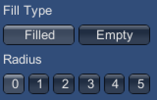
Give our UI another selection grid so we can control the stencil's radius. A range from zero to five should be plenty for a small map.
	private static string[] radiusNames = {"0", "1", "2", "3", "4", "5"};

	private int fillTypeIndex, radiusIndex;

	private void OnGUI () {
		GUILayout.BeginArea(new Rect(4f, 4f, 150f, 500f));
		GUILayout.Label("Fill Type");
		fillTypeIndex = GUILayout.SelectionGrid(fillTypeIndex, fillTypeNames, 2);
		GUILayout.Label("Radius");
		radiusIndex = GUILayout.SelectionGrid(radiusIndex, radiusNames, 6);
		GUILayout.EndArea();
	}
We now have to set the stencil's radius and center in VoxelMap.EditVoxels. Because the stencil holds all data that we need, we can remove the coordinates from the call to VoxelGrid.Apply. I've also renamed the coordinate variables so it's clear that we're working with a center.
	private void EditVoxels (Vector3 point) {
		int centerX = (int)((point.x + halfSize) / voxelSize);
		int centerY = (int)((point.y + halfSize) / voxelSize);
		int chunkX = centerX / voxelResolution;
		int chunkY = centerY / voxelResolution;
		centerX -= chunkX * voxelResolution;
		centerY -= chunkY * voxelResolution;

		VoxelStencil activeStencil = new VoxelStencil();
		activeStencil.Initialize(fillTypeIndex == 0, radiusIndex);
		activeStencil.SetCenter(centerX, centerY);
		chunks[chunkY * chunkResolution + chunkX].Apply(activeStencil);
	}
VoxelGrid.Apply has to loop over all voxels that are covered by the stencil. So we use the stencil's properties to perform a double loop and compute the array indices.
	public void Apply (VoxelStencil stencil) {
		int xStart = stencil.XStart;
		int xEnd = stencil.XEnd;
		int yStart = stencil.YStart;
		int yEnd = stencil.YEnd;

		for (int y = yStart; y <= yEnd; y++) {
			int i = y * resolution + xStart;
			for (int x = xStart; x <= xEnd; x++, i++) {
				voxels[i] = stencil.Apply(x, y);
			}
		}
		SetVoxelColors();
	}
This seems to work, but only when we stay in the center of individual voxel grids, because otherwise we go out of bounds. We have to cut off the area that falls outside the voxel grid.
		int xStart = stencil.XStart;
		if (xStart < 0) {
			xStart = 0;
		}
		int xEnd = stencil.XEnd;
		if (xEnd >= resolution) {
			xEnd = resolution - 1;
		}
		int yStart = stencil.YStart;
		if (yStart < 0) {
			yStart = 0;
		}
		int yEnd = stencil.YEnd;
		if (yEnd >= resolution) {
			yEnd = resolution - 1;
		}
We no longer get errors, but we get unexpected results when using a nonzero radius. This happens because we're currently only applying the stencil to the voxel grid that contains its center. So the stencil gets cut off by chunk boundaries.
To fix this, we basically have to do the same thing in VoxelMap.EditVoxels as we did in VoxelGrid.Apply. Instead of looping over covered voxels, we have to loop over covered chunks. So we define a voxel area and convert it into chunk bounds, then loop over those chunks. We also have to reset the stencil's center so it matches each chunk's local coordinates.
	private void EditVoxels (Vector3 point) {
		int centerX = (int)((point.x + halfSize) / voxelSize);
		int centerY = (int)((point.y + halfSize) / voxelSize);

		int xStart = (centerX - radiusIndex) / voxelResolution;
		if (xStart < 0) {
			xStart = 0;
		}
		int xEnd = (centerX + radiusIndex) / voxelResolution;
		if (xEnd >= chunkResolution) {
			xEnd = chunkResolution - 1;
		}
		int yStart = (centerY - radiusIndex) / voxelResolution;
		if (yStart < 0) {
			yStart = 0;
		}
		int yEnd = (centerY + radiusIndex) / voxelResolution;
		if (yEnd >= chunkResolution) {
			yEnd = chunkResolution - 1;
		}

		VoxelStencil activeStencil = new VoxelStencil();
		activeStencil.Initialize(fillTypeIndex == 0, radiusIndex);

		int voxelYOffset = yStart * voxelResolution;
		for (int y = yStart; y <= yEnd; y++) {
			int i = y * chunkResolution + xStart;
			int voxelXOffset = xStart * voxelResolution;
			for (int x = xStart; x <= xEnd; x++, i++) {
				activeStencil.SetCenter(centerX - voxelXOffset, centerY - voxelYOffset);
				chunks[i].Apply(activeStencil);
				voxelXOffset += voxelResolution;
			}
			voxelYOffset += voxelResolution;
		}
	}
Adding a Circular Stencil
Our current stencil is square, but that's not the only possible shape. Let's add the possibility to choose between a square and a circular stencil.
To easily support different stencils, we'll use inheritance. VoxelStencil will be the base class. First, make its fields protected instead of private, so subclasses can access them. Also declare its methods as virtual, so subclasses can override them if needed.
	protected bool fillType;

	protected int centerX, centerY, radius;

	public virtual void Initialize (bool fillType, int radius) {
		this.fillType = fillType;
		this.radius = radius;
	}

	public virtual void SetCenter (int x, int y) {
		centerX = x;
		centerY = y;
	}

	public virtual bool Apply (int x, int y) {
		return fillType;
	}
Because a circular stencil won't touch all voxels covered by its rectangular bounds, we need to way to not change a voxel. We can do so by passing the original voxel value to the stencil's Apply method, so let's add it to the parameter list.
	public virtual bool Apply (int x, int y, bool voxel) {
		return fillType;
	}
Of course we now have to pass along the voxel in VoxelGrid.Apply.
voxels[i] = stencil.Apply(x, y, voxels[i]);
We are now ready to add a new stencil class. We'll name it VoxelStencilCircle. To determine whether a voxel is inside the circle we can compare square radiuses. So let's override Initialize to store a precomputed square radius. Then inside Apply we check if the coordinates fall inside the circle. If so, we return the stencil's fill type, otherwise we return the original value.
using UnityEngine;

public class VoxelStencilCircle : VoxelStencil {

	private int sqrRadius;

	public override void Initialize (bool fillType, int radius) {
		base.Initialize (fillType, radius);
		sqrRadius = radius * radius;
	}

	public override bool Apply (int x, int y, bool voxel) {
		x -= centerX;
		y -= centerY;
		if (x * x + y * y <= sqrRadius) {
			return fillType;
		}
		return voxel;
	}
}
Now we have to add a new configuration option to our UI.
	private static string[] stencilNames = {"Square", "Circle"};

	private int fillTypeIndex, radiusIndex, stencilIndex;

	private void OnGUI () {
		GUILayout.BeginArea(new Rect(4f, 4f, 150f, 500f));
		GUILayout.Label("Fill Type");
		fillTypeIndex = GUILayout.SelectionGrid(fillTypeIndex, fillTypeNames, 2);
		GUILayout.Label("Radius");
		radiusIndex = GUILayout.SelectionGrid(radiusIndex, radiusNames, 6);
		GUILayout.Label("Stencil");
		stencilIndex = GUILayout.SelectionGrid(stencilIndex, stencilNames, 2);
		GUILayout.EndArea();
	}
And instead of creating a new stencil instance each time, we store an instance of each in an array.
	private VoxelStencil[] stencils = {
		new VoxelStencil(),
		new VoxelStencilCircle()
	};
So in EditVoxels we can use the currently selected one.
VoxelStencil activeStencil = stencils[stencilIndex];
And now we can draw blocky circles!
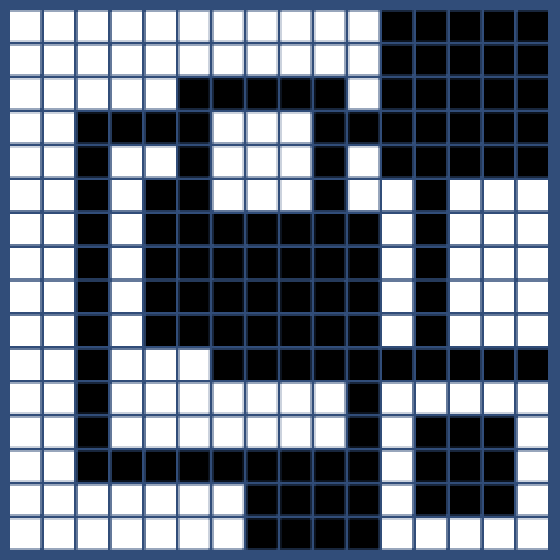
Marching the Squares
So far we've been using individual quads to show a blocky grid. This is fine in some situations, but it is very useful to be able to produce a single mesh per grid chunk.
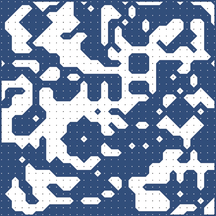
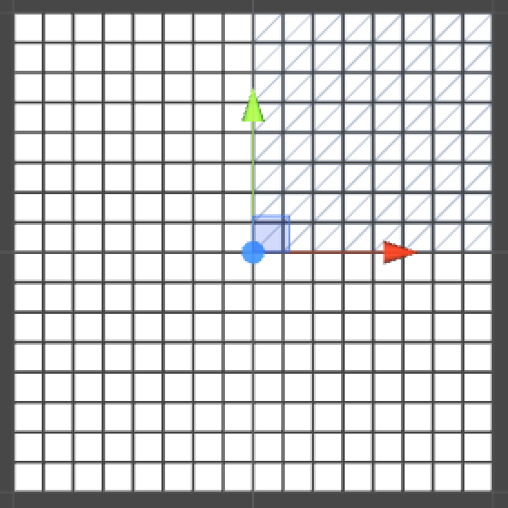
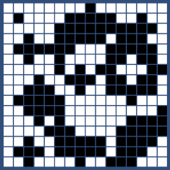
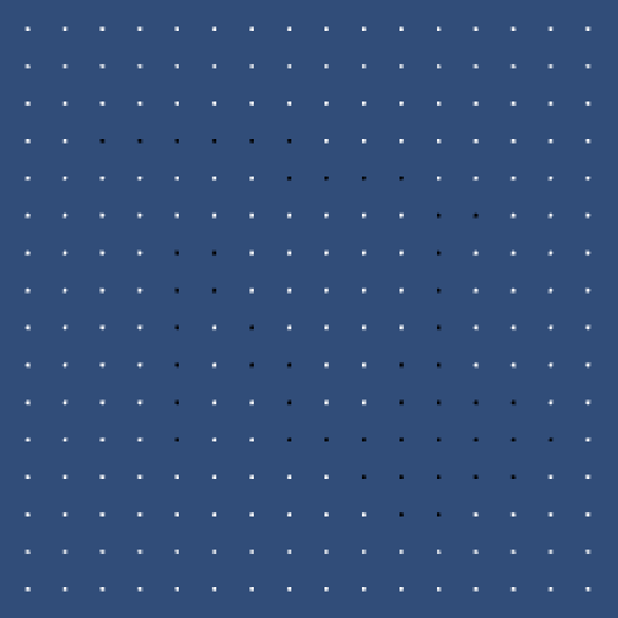
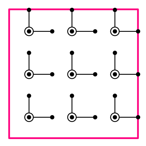
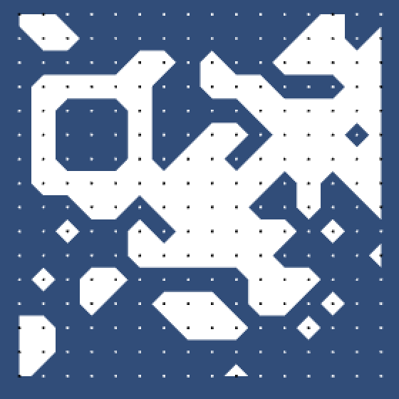
As the voxels are either filled or empty, the transition between those two states happens somewhere in between the voxels. To represent this with a mesh, we need to place triangles in the square areas between voxels. These areas are usually known as cells. You can see these square when you reduce the voxel quads to small dots. As they provide a handy visual aid, we'll keep them even after adding the mesh. To keep the dots visible, put them a bit closer to the camera.
		o.transform.localPosition = new Vector3((x + 0.5f) * voxelSize, (y + 0.5f) * voxelSize, -0.01f);
		o.transform.localScale = Vector3.one * voxelSize * 0.1f;
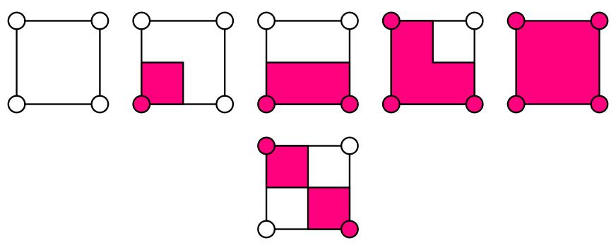
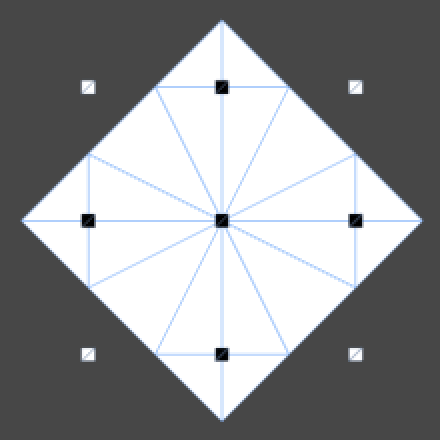
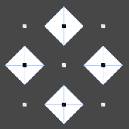
Recalling how the full-size quads filled the grid previously, you can work out that there were sixteen different ways that the square areas could be filled. If you then filter out patterns that are rotated version of each other together, you end up with six groups.
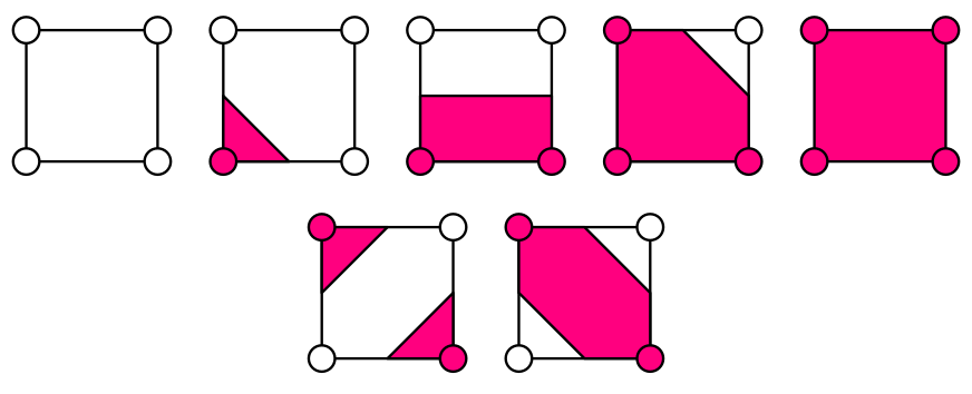
We're going to use the Marching Squares algorithm to triangulate these squares. We will reproduce the configurations that we discovered above, but we'll directly connect the square edges instead of going through the center. We're basically taking shortcuts along diagonals. This is known as primal contouring, while the alternative is dual contouring.
We still have the same six group types, but one of them is now ambiguous. When there are two filled voxels that both share empty neighbors, do we connect them diagonally or disconnect them? Neither option is better than the other, so let's just pick one and be consistent about it. I choose to keep them disconnected.
Preparing for Triangulation
Before we start with our mesh, first create simple flat shader that requires no uv and normal data, so we don't have to worry about that. Here's an adjusted default surface shader that takes care of this. I removed the texture, injected a fixed normal, and added a color property. The dummy is needed to prevent a compiler error.
Shader "Custom/2D Flat" {
	Properties {
		_Color ("Color", Color) = (1,1,1,1)
	}
	SubShader {
		Tags { "RenderType"="Opaque" }
		LOD 200

		CGPROGRAM
		#pragma surface surf Lambert vertex:vert

		fixed4 _Color;

		struct Input {
			float dummy;
		};

		void vert (inout appdata_full v) {
			v.normal = float3(0, 0, -1);
		}

		void surf (Input IN, inout SurfaceOutput o) {
			o.Albedo = _Color.rgb;
		}
		ENDCG
	}
	FallBack "Diffuse"
}
Add a MeshFilter and MeshRenderer component to the Voxel Grid prefab, then create a new material that uses the custom shader and assign it to the prefab.
Next, VoxelGrid needs a Mesh variable. We also need to accumulate vertices and triangle data somehow. Because we don't know ahead of time how many vertices and triangles will be generated, let's add two list variables so we don't have to worry about size limits.
using UnityEngine;
using System.Collections.Generic;

[SelectionBase]
public class VoxelGrid : MonoBehaviour {

	private Mesh mesh;

	private List<Vector3> vertices;
	private List<int> triangles

	…
}
Now we are no longer just setting voxel colors. Replace the call to SetVoxelColors at the end of Initialize with the initialization of our mesh data and a call to a new Refresh method. Also replace the call to SetVoxelColors in Apply with the invocation of Refresh.
	public void Initialize (int resolution, float size) {
		…

		GetComponent<MeshFilter>().mesh = mesh = new Mesh();
		mesh.name = "VoxelGrid Mesh";
		vertices = new List<Vector3>();
		triangles = new List<int>();
		Refresh();
	}

	public void Apply (VoxelStencil stencil) {
		…
		Refresh();
	}
Refreshing now entails both setting the old colors and a new triangulation, for which we add a placeholder method.
	private void Refresh () {
		SetVoxelColors();
		Triangulate();
	}

	private void Triangulate () {
	}
Adding a Voxel Class
We will need to place vertices at voxel positions and halfway along the edge between two voxels. We could compute these positions each time we need to position a vertex, but it's more convenient to precompute and store them, so let's do that.
Storing voxel positions is easy, as we already compute those. We could either store the edge positions separately, or along with the voxel data. If we consider a voxel to define the bottom-left corner of a cell, then it is adjacent to the bottom and left edges of that cell as well. As this is true for all voxels, we can store these two edge positions along with the voxel position. This would mean that the rightmost and topmost voxels have edge data that's poking outside the grid, but we'll worry about that later.
To store this data in a convenient way, let's upgrade our voxel booleans into full-fledged objects. Add a new Voxel class that contains the boolean voxel state, its position, and the edge positions for the X and Y directions. Also mark the class as serializable, so the voxel data can survive code compilation while Unity is in play mode.
using UnityEngine;
using System;

[Serializable]
public class Voxel {

	public bool state;

	public Vector2 position, xEdgePosition, yEdgePosition;
}
Give it a constructor method in which it calculates its positions values. It needs to know its coordinates and size to do so, though we don't need to store them.
	public Voxel (int x, int y, float size) {
		position.x = (x + 0.5f) * size;
		position.y = (y + 0.5f) * size;

		xEdgePosition = position;
		xEdgePosition.x += size * 0.5f;
		yEdgePosition = position;
		yEdgePosition.y += size * 0.5f;
	}
Now we need need to modify VoxelGrid a bit. Change the voxel array's type, create new voxel instances, and access the voxel's state variable, instead of just working with booleans.
	private Voxel[] voxels;

	public void Initialize (int resolution, float size) {
		this.resolution = resolution;
		voxelSize = size / resolution;
		voxels = new Voxel[resolution * resolution];
		…
	}

	private void CreateVoxel (int i, int x, int y) {
		…
		voxels[i] = new Voxel(x, y, voxelSize);
	}

	private void SetVoxelColors () {
		for (int i = 0; i < voxels.Length; i++) {
			voxelMaterials[i].color = voxels[i].state ? Color.black : Color.white;
		}
	}

	public void Apply (VoxelStencil stencil) {
		…
				voxels[i].state = stencil.Apply(x, y, voxels[i].state);
		…
	}
Triangulating
It is now time to fill in the Triangulate method. We start by clearing the old data, then triangulate all cell rows, then assign new vertices and triangles to the mesh.
	private void Triangulate () {
		vertices.Clear();
		triangles.Clear();
		mesh.Clear();

		TriangulateCellRows();

		mesh.vertices = vertices.ToArray();
		mesh.triangles = triangles.ToArray();
	}
Because cells sit between voxels, the cell resolution of a grid is one lower than its voxel resolution. That means our TriangulateCellRows method must perform a double loop one step shorter than for voxels, as it triangulates each cell.
As cells are identified by their lower-left voxel corner, we have to keep track of the voxel index. Also, because we're skipping the last voxel each row, we have to increase the index one more time per row, so we increment it in both loops.
	private void TriangulateCellRows () {
		int cells = resolution - 1;
		for (int i = 0, y = 0; y < cells; y++, i++) {
			for (int x = 0; x < cells; x++, i++) {
				TriangulateCell();
			}
		}
	}
A cell is defined by its four corner voxels, so we have to provide them to TriangulateCell. Let's order them just in the same way the entire voxel grid is ordered, first along X, then along Y.
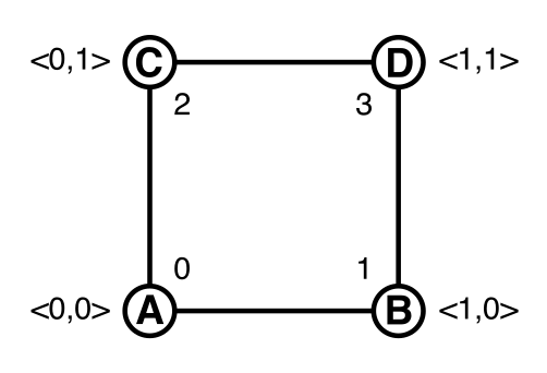
The A voxel is simply the voxel with the current index. The B voxel is one step further. The C voxel is on the next row, so we have to add the resolution to the index. And the D voxel is one step further than C.
	private void TriangulateCellRows () {
		int cells = resolution - 1;
		for (int i = 0, y = 0; y < cells; y++, i++) {
			for (int x = 0; x < cells; x++, i++) {
				TriangulateCell(
					voxels[i],
					voxels[i + 1],
					voxels[i + resolution],
					voxels[i + resolution + 1]);
			}
		}
	}

	private void TriangulateCell (Voxel a, Voxel b, Voxel c, Voxel d) {
	}
TriangulateCell now needs to figure out the configuration of the cell's corners. We can identify the sixteen possible cases by assigning numbers to corners and combining them like bit masks. We assign the first bit to A, which is the number 1. The second bit goes to B, so its number is 2. C gets the third bit, which makes it 4. And D has the fourth bit, being 8.
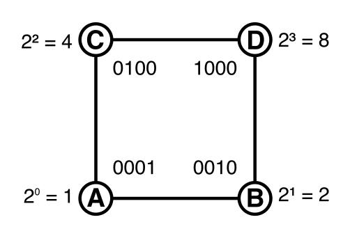
If we combine the numbers of filled corners using the binary OR operator, we end up with a number in the 0–15 range. This number tells us which of the sixteen possible types our cell has.
		int cellType = 0;
		if (a.state) {
			cellType |= 1;
		}
		if (b.state) {
			cellType |= 2;
		}
		if (c.state) {
			cellType |= 4;
		}
		if (d.state) {
			cellType |= 8;
		}
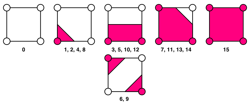
Now we have to perform a different triangulation for each of the sixteen cases. We'll use a switch statement pick the right one.
First up is case 0, which is trivial as the cell is empty.
		switch (cellType) {
		case 0:
			return;
		}
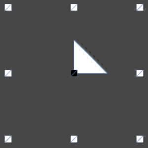
Case 1 requires placing one triangle at the bottom left of the cell, between A's position and its adjacent edges. Make sure to supply the points in a clockwise order, so the triangle will face the camera.
		switch (cellType) {
		case 0:
			return;
		case 1:
			AddTriangle(a.position, a.yEdgePosition, a.xEdgePosition);
			break;
		}
We just assumed that we had an AddTriangle method, but we didn't so we have to create it now. First fetch the current vertex count, which equals the index of the next vertex to be added. Then just add the vertices to the vertex list and their indices to the triangle list.
	private void AddTriangle (Vector3 a, Vector3 b, Vector3 c) {
		int vertexIndex = vertices.Count;
		vertices.Add(a);
		vertices.Add(b);
		vertices.Add(c);
		triangles.Add(vertexIndex);
		triangles.Add(vertexIndex + 1);
		triangles.Add(vertexIndex + 2);
	}
Try it out somewhere in the middle of a chunk. Filling a voxel should produce a single triangle. It won't seem to work right along chunk edges, but don't worry about that just yet.
The other three single-corner cases work the same way, they just require different points. I've grouped similar cases together here, but you can also sort them numerically.
		case 2:
			AddTriangle(b.position, a.xEdgePosition, b.yEdgePosition);
			break;
		case 4:
			AddTriangle(c.position, c.xEdgePosition, a.yEdgePosition);
			break;
		case 8:
			AddTriangle(d.position, b.yEdgePosition, c.xEdgePosition);
			break;
Let's now take care of the cell types that contain rectangles. For that, we have to add a method for quads. It needs to insert four vertices and two triangles that share an edge and two vertices.
	private void AddQuad (Vector3 a, Vector3 b, Vector3 c, Vector3 d) {
		int vertexIndex = vertices.Count;
		vertices.Add(a);
		vertices.Add(b);
		vertices.Add(c);
		vertices.Add(d);
		triangles.Add(vertexIndex);
		triangles.Add(vertexIndex + 1);
		triangles.Add(vertexIndex + 2);
		triangles.Add(vertexIndex);
		triangles.Add(vertexIndex + 2);
		triangles.Add(vertexIndex + 3);
	}
Now we can support cases 3, 5, 10, 12, and 15.
		case 3:
			AddQuad(a.position, a.yEdgePosition, b.yEdgePosition, b.position);
			break;
		case 5:
			AddQuad(a.position, c.position, c.xEdgePosition, a.xEdgePosition);
			break;
		case 10:
			AddQuad(a.xEdgePosition, c.xEdgePosition, d.position, b.position);
			break;
		case 12:
			AddQuad(a.yEdgePosition, c.position, d.position, b.yEdgePosition);
			break;
		case 15:
			AddQuad(a.position, c.position, d.position, b.position);
			break;
The cases with three filled and one empty voxel each require a square with a single corner cut away. This is basically a pentagon that's stretched out of shape. A pentagon can be created with five vertices and three triangles that form a small fan.
	private void AddPentagon (Vector3 a, Vector3 b, Vector3 c, Vector3 d, Vector3 e) {
		int vertexIndex = vertices.Count;
		vertices.Add(a);
		vertices.Add(b);
		vertices.Add(c);
		vertices.Add(d);
		vertices.Add(e);
		triangles.Add(vertexIndex);
		triangles.Add(vertexIndex + 1);
		triangles.Add(vertexIndex + 2);
		triangles.Add(vertexIndex);
		triangles.Add(vertexIndex + 2);
		triangles.Add(vertexIndex + 3);
		triangles.Add(vertexIndex);
		triangles.Add(vertexIndex + 3);
		triangles.Add(vertexIndex + 4);
	}
This allows for cases 7, 11, 13, and 14. I decided to center the fans on the corner opposite to the empty one.
		case 7:
			AddPentagon(a.position, c.position, c.xEdgePosition, b.yEdgePosition, b.position);
			break;
		case 11:
			AddPentagon(b.position, a.position, a.yEdgePosition, c.xEdgePosition, d.position);
			break;
		case 13:
			AddPentagon(c.position, d.position, b.yEdgePosition, a.xEdgePosition, a.position);
			break;
		case 14:
			AddPentagon(d.position, b.position, a.xEdgePosition, a.yEdgePosition, c.position);
			break;
		}
Only the two opposite-corner cases are still missing, 6 and 9. I decided to disconnect them, so they require two triangles each, which you can copy from the single-triangle cases. Connecting them would've required a hexagon instead.
		case 6:
			AddTriangle(b.position, a.xEdgePosition, b.yEdgePosition);
			AddTriangle(c.position, c.xEdgePosition, a.yEdgePosition);
			break;
		case 9:
			AddTriangle(a.position, a.yEdgePosition, a.xEdgePosition);
			AddTriangle(d.position, b.yEdgePosition, c.xEdgePosition);
			break;
Connecting Chunks
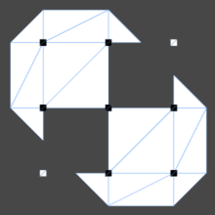
We are now able to triangulate surfaces around filled voxels, but there are gaps between chunks. These seams consist of cells whose corners belong to multiple different voxel grids.

Because voxels contain the positions of their right and top edge, it makes sense that a VoxelGrid takes care of triangulating the gap cells along its right and top border. To do so, it needs to fetch voxel data from its neighbors. So let's store references to those neighbors. We need the right and top neighbor, and also the top-right neighbor for where two seams cross.
public VoxelGrid xNeighbor, yNeighbor, xyNeighbor;
We have to establish these relationships when VoxelMap creates the chunks. When creating a new chunk, if it's not the first of a row, then it's the X neighbor of the previous chunk. Likewise along the Y direction, and for the diagonal relationship.
	private void CreateChunk (int i, int x, int y) {
		VoxelGrid chunk = Instantiate(voxelGridPrefab) as VoxelGrid;
		chunk.Initialize(voxelResolution, chunkSize);
		chunk.transform.parent = transform;
		chunk.transform.localPosition = new Vector3(x * chunkSize - halfSize, y * chunkSize - halfSize);
		chunks[i] = chunk;
		if (x > 0) {
			chunks[i - 1].xNeighbor = chunk;
		}
		if (y > 0) {
			chunks[i - chunkResolution].yNeighbor = chunk;
			if (x > 0) {
				chunks[i - chunkResolution - 1].xyNeighbor = chunk;
			}
		}
	}
So now chunks depend on their right and top neighbors when triangulating. This means that we have to reverse our chunk loop in EditVoxels. If we didn't, the bottom-left chunks would triangulate using the current voxel states of their neighbors, then those neighbors would change their voxels states and triangulate as well, leading to wrong connections. Going from top-right to bottom-left prevents this.
		int voxelYOffset = yEnd * voxelResolution;
		for (int y = yEnd; y >= yStart; y--) {
			int i = y * chunkResolution + xEnd;
			int voxelXOffset = xEnd * voxelResolution;
			for (int x = xEnd; x >= xStart; x--, i--) {
				activeStencil.SetCenter(centerX - voxelXOffset, centerY - voxelYOffset);
				chunks[i].Apply(activeStencil);
				voxelXOffset -= voxelResolution;
			}
			voxelYOffset -= voxelResolution;
		}
Adding Gap Cells Along X
It's time to fill those gaps! First consider the single gap cell along X at the end of each row. We need to know two voxels from the X neighbor to triangulate it.
We could fetch the two required voxels again for each row, but most of the time we end up needing the same voxel twice, once as corner D and once as corner B.
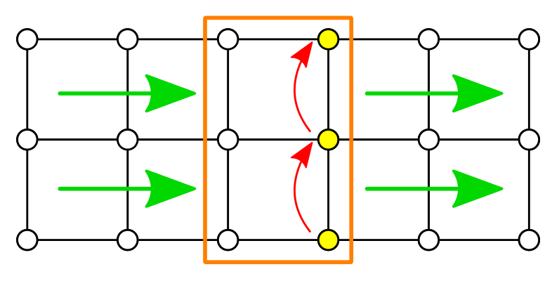
We actually cannot directly use the neighbor's voxel data, we have to translate the positions from one local space to the other. To keep track of that, add some dummy voxel objects to VoxelGrid. Let's remember one for the X and Y directions each. Also add a third one to help transport the voxel data along rows.
To perform the position conversions, the grid now also has to remember its size.
	private float voxelSize, gridSize;

	private Voxel dummyX, dummyY, dummyT;

	public void Initialize (int resolution, float size) {
		this.resolution = resolution;
		gridSize = size;
		voxelSize = size / resolution;
		voxels = new Voxel[resolution * resolution];
		voxelMaterials = new Material[voxels.Length];

		dummyX = new Voxel();
		dummyY = new Voxel();
		dummyT = new Voxel();

		…
	}
We don't need any initialization for dummy voxels, we didn't provide any arguments when invoking their constructor. To support this, we have to add an empty constructor to Voxel.
public Voxel () {}
Let's also have it take care off becoming a dummy of another voxel. For that, add a method specifically for becoming a dummy along the X direction, which takes care of applying some offset to the X coordinates. We will always use the grid's size as the offset, but voxels don't have this information, so we provide it as an argument when calling the method later.
	public void BecomeXDummyOf (Voxel voxel, float offset) {
		state = voxel.state;
		position = voxel.position;
		xEdgePosition = voxel.xEdgePosition;
		yEdgePosition = voxel.yEdgePosition;
		position.x += offset;
		xEdgePosition.x += offset;
		yEdgePosition.x += offset;
	}
Now that we can create dummy voxels along X, start the whole triangulation process by grabbing the first dummy, if possible. That gives us corner B for the gap cell at the end of the first row.
	private void Triangulate () {
		vertices.Clear();
		triangles.Clear();
		mesh.Clear();

		if (xNeighbor != null) {
			dummyX.BecomeXDummyOf(xNeighbor.voxels[0], gridSize);
		}
		TriangulateCellRows();

		mesh.vertices = vertices.ToArray();
		mesh.triangles = triangles.ToArray();
	}
So each time we finish a row, if there is an X neighbor, we triangulate a gap cell.
	private void TriangulateCellRows () {
		int cells = resolution - 1;
		for (int i = 0, y = 0; y < cells; y++, i++) {
			for (int x = 0; x < cells; x++, i++) {
				TriangulateCell(
					voxels[i],
					voxels[i + 1],
					voxels[i + resolution],
					voxels[i + resolution + 1]);
			}
			if (xNeighbor != null) {
				TriangulateGapCell(i);
			}
		}
	}
When triangulating a cap cell, we know that dummyX contains our corner B. We also know that we're at the last voxel of a now, so the next one would be the first of the next row, which gives us the index for corner D in the neighboring grid.
But we must also make sure that dummyX becomes corner B for the next row's gap cell, which is the same as our current corner D. We can do this by swapping dummyX and dummyT and putting the new corner in dummyB. To not lose our object references, we have to use a third temporary variable while performing the swap.
	private void TriangulateGapCell (int i) {
		Voxel dummySwap = dummyT;
		dummySwap.BecomeXDummyOf(xNeighbor.voxels[i + 1], gridSize);
		dummyT = dummyX;
		dummyX = dummySwap;
		TriangulateCell(voxels[i], dummyT, voxels[i + resolution], dummyX);
	}

We now connect chunks horizontally, but unfortunately it doesn't always work. It goes wrong when the leftmost voxels of a chunk are edited, but the chunk to the left of that isn't touched. A simple fix is to add a one-voxel padding to the bottom and left sides when determining which chunks to update in VoxelMap.EditVoxels. This guarantees that chunks also re-triangulate when their gap cells have changed.
		int centerX = (int)((point.x + halfSize) / voxelSize);
		int centerY = (int)((point.y + halfSize) / voxelSize);

		int xStart = (centerX - radiusIndex - 1) / voxelResolution;
		if (xStart < 0) {
			xStart = 0;
		}
		int xEnd = (centerX + radiusIndex) / voxelResolution;
		if (xEnd >= chunkResolution) {
			xEnd = chunkResolution - 1;
		}
		int yStart = (centerY - radiusIndex - 1) / voxelResolution;
		if (yStart < 0) {
			yStart = 0;
		}
		int yEnd = (centerY + radiusIndex) / voxelResolution;
		if (yEnd >= chunkResolution) {
			yEnd = chunkResolution - 1;
		}
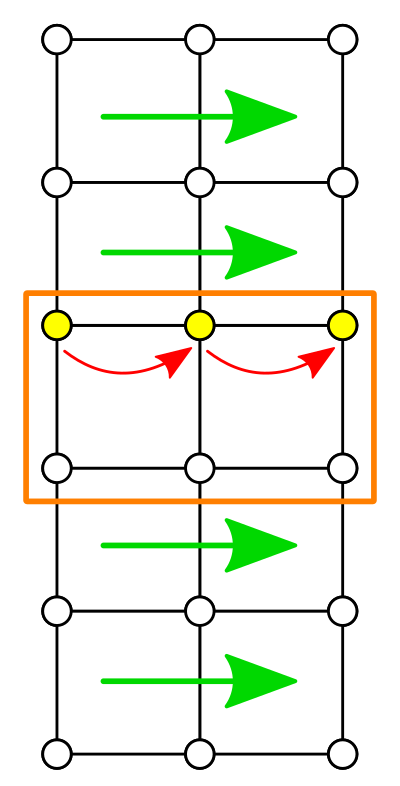
Adding Gap Cells Along Y
We also have to add gap cells in the Y direction, but in this case we work through an entire gap row at once.
First, add another become-dummy method to Voxel, which offsets in the Y direction.
	public void BecomeYDummyOf (Voxel voxel, float offset) {
		state = voxel.state;
		position = voxel.position;
		xEdgePosition = voxel.xEdgePosition;
		yEdgePosition = voxel.yEdgePosition;
		position.y += offset;
		xEdgePosition.y += offset;
		yEdgePosition.y += offset;
	}
Then add a method to triangulate the gap row to VoxelGrid. It runs along the top row of voxels and the bottom row of its Y-neighbor, swapping between dummyY and dummyT.
	private void TriangulateGapRow () {
		dummyY.BecomeYDummyOf(yNeighbor.voxels[0], gridSize);
		int cells = resolution - 1;
		int offset = cells * resolution;

		for (int x = 0; x < cells; x++) {
			Voxel dummySwap = dummyT;
			dummySwap.BecomeYDummyOf(yNeighbor.voxels[x + 1], gridSize);
			dummyT = dummyY;
			dummyY = dummySwap;
			TriangulateCell(voxels[x + offset], voxels[x + offset + 1], dummyT, dummyY);
		}
	}
And of course invoke it in Triangulate, after all other rows have been done.
		if (xNeighbor != null) {
			dummyX.BecomeXDummyOf(xNeighbor.voxels[0], gridSize);
		}
		TriangulateCellRows();
		if (yNeighbor != null) {
			TriangulateGapRow();
		}

To fill the last gap, Voxel needs to support one more become-dummy method, which offsets in both directions.
	public void BecomeXYDummyOf (Voxel voxel, float offset) {
		state = voxel.state;
		position = voxel.position;
		xEdgePosition = voxel.xEdgePosition;
		yEdgePosition = voxel.yEdgePosition;
		position.x += offset;
		position.y += offset;
		xEdgePosition.x += offset;
		xEdgePosition.y += offset;
		yEdgePosition.x += offset;
		yEdgePosition.y += offset;
	}
This allows us to add the last gap cell at the end of the gap row. This cell is special because each of its corners belongs to a different grid. Corner A is the last voxel of the chunk itself. Corner B was already put in dummyX, and corner C is stored in dummyY. Corner D is the first voxel of the diagonal neighbor, which we can store in dummyT.
	private void TriangulateGapRow () {
		…

		if (xNeighbor != null) {
			dummyT.BecomeXYDummyOf(xyNeighbor.voxels[0], gridSize);
			TriangulateCell(voxels[voxels.Length - 1], dummyX, dummyY, dummyT);
		}
	}
That does it! You now have a fully triangulated voxel map, even though it is partitioned into separate chunks, each taking care of its own mesh.
Of course the resulting surface is very angular, which is great if that's the style you're going for, but quite limiting otherwise. This is because we're working with binary voxel data. All we know is whether a voxel is filled or empty, which gives us very little to work with. Including more information allows far more variety. This is something we'll explore in the next tutorial.
Enjoyed the tutorial? Help me make more by becoming a patron!
Downloads
- marching-squares-01.unitypackage
- The project after Showing a Bitmap.
- marching-squares-02.unitypackage
- The project after Stenciling.
- marching-squares-finished.unitypackage
- The finished project.