Making a Clock
This is the first tutorial in a series that introduces you to the Godot Engine, version 4. It starts at the absolute beginning and guides you through the process of creating a simple analog clock. In this tutorial we get to know the Godot editor and build a visual representation of a clock. The next tutorial will introduce programming to animate the clock, but for now we focus of the basics of the editor.
At the bottom of my tutorials you'll find links to their license and an online repository containing the finished project.
Creating a Project
Before we can create anything we need to get the Godot editor application and create a project with it. There are various ways to get the editor. I recommend getting it directly from the official website and installing it on your system. This gives you the most control and has the least overhead, but this tutorial works no matter how you got Godot running.
Throughout my tutorials you you will encounter question-answer sections that provide supplementary information that isn't essential. On webpages they are collapsed by default, only showing the question. Clicking the question will reveal the answer.
How do you pronounce Godot?
It is typically pronounced like goh-doh
, or goth dough
without the th
.
It's a French name, from the theatrical play En attendant Godot
or Waiting for Godot
. It has no canonical meaning. It refers to the titular character of the play, who never arrives.
Getting the Editor
If you don't already have it, go to godotengine.org and click Download Latest
or the Download
link shown at the top of the page. This will take you to a page where you can download Godot 4 for your system, if you are using a desktop or laptop computer.
You will be offered two choices: Godot Engine
and Godot Engine - .NET
. The latter is an alternative version of the engine that supports the .NET environment, which allows programming in C#.
We won't be using C# for the first few tutorials, so you can grab the regular editor version. That version just works while the .NET version might require additional setup. Both versions should be unified in the future, after which this will no longer be an issue.
Which exact version should I get?
Simply grab the latest version that is presented by the web page. That's currently 4.1.3. Version 4.2 will be released soon and that will also be fine.
Project Manager
Once you have Godot installed on your system open the app. You will be presented with a window titled Godot Engine - Project Manager
.
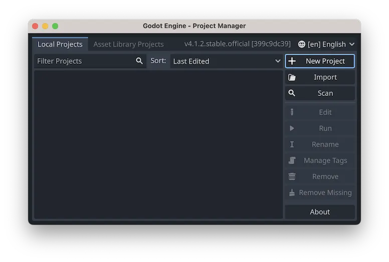
This is the project manager hub, where you can create and keep track of your Godot projects. If you have never opened Godot before the project list will be empty. Also, the window will use Godot's default editor theme, which is dark. This theme is independent of your system's theme.
To create a new project click the New Project button on the right side of the window. This pops up a Create New Project
window. Here you can give your project a name and select a location on your system to store the project that you are about to create, via the Browse button. The project name and folder name don't need to match and you can change the project name later.
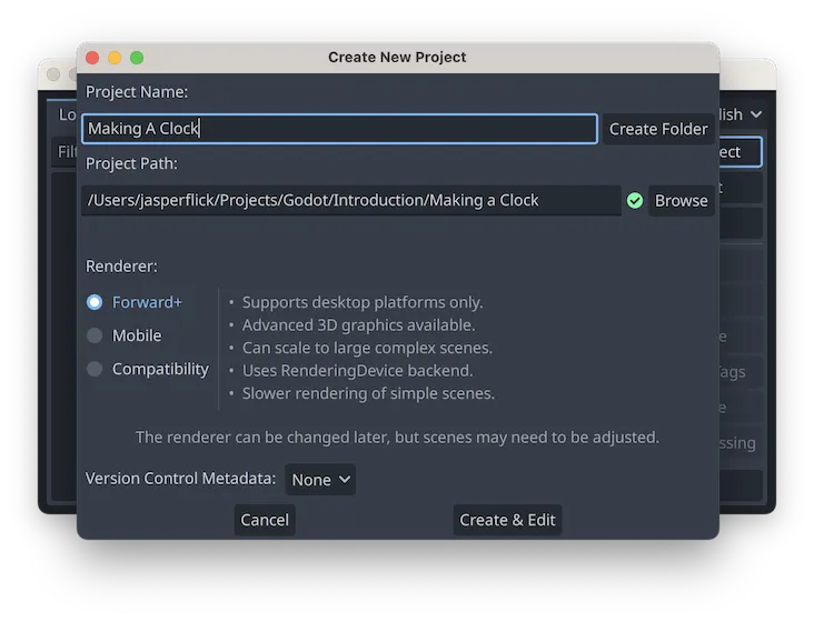
Besides that you are also offered a choice for the renderer that your project will use. This determines how Godot visualizes your project. As mentioned, this can be changed later. We keep the default Forward+ option.
There is also a Version Control Metadata option, set to Git by default. It is a good idea to use version control for serious projects, but even then you do not need to use this option. It enables some in-editor version control features like difference-checking that stand-alone version control apps also provide. So let's set it to None.
Click the Create & Edit button to generate the project and open it in the Godot editor. From now on when you open Godot your project will be listed by the project manager and you can open it from there.
Selecting a Theme
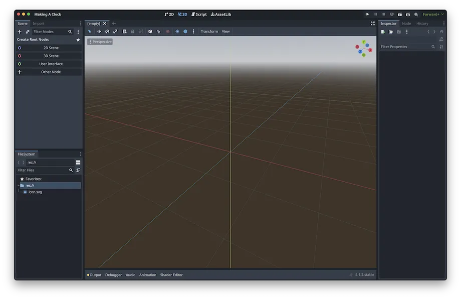
Once the editor has loaded it will be presented to you with its default layout. We will keep this layout throughout the tutorials, but you can customize it as you like. There are various areas and toolbars that we will describe as needed. Most prominent is the central viewport, which shows a 3D view by default.
Before we do anything else, let's select a different editor theme. One of the app's main menu items, shown under its title bar, or in the menu bar on a Mac, is Editor. Clicking it reveals its submenu items, the first being Editor Settings.... Click that, or use the keyboard shortcut displayed for it. That opens the Editor Settings
window.
The window has two tabs, with General selected by default. You can filter for settings by name here, or browse to the desired category via the collapsible list on the left side. Select Theme under Interface. Then pick a theme for the Preset option in the panel on the right.
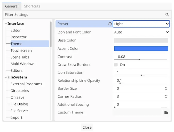
The Default theme is the one we used to far. You can select another preset theme here or use the other options to create a custom one. From now on, which theme is shown in the tutorial screenshots depends on the theme that you have selected for this website. Godot's Default theme is used for dark and Light is used for light web pages. This applies to all screenshots that are significantly affected by the theme.
How can I change this website's theme?
There is a settings button at the top left of the page. Clicking it opens a panel where you can pick a dark or light website theme, whichever you prefer. This changes the colors of all pages, code highlighting, and some screenshots. The default auto theme is dark or light based on your browser and system settings. The other settings are not relevant for this tutorial.
Output Messages
There is a bar at the bottom of the editor, below the viewport, that lists a few options. The first is Output. It has an obvious colored dot in front of it that is designed to draw our attention to it. Clicking Output will expand a panel, showing Godot's output log.
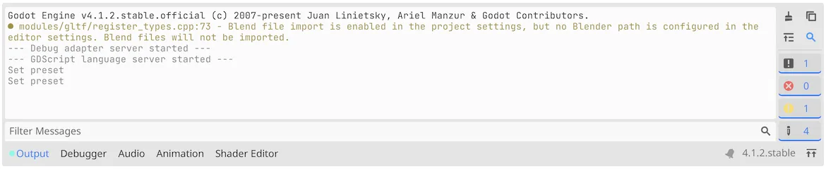
Godot logs messages, warnings, and errors in here. It starts with an initialization message, followed by a warning concerning some Blend file import option. After that follows some more initialization and then a log of things that we did in the editor. Set preset
refers to selecting a preset theme.
You can use the buttons at the right of the log to filter and clear it, but the Blend file warning will pop up every time we open our project. It warns us that our project is set to import Blend files, but no path is configured for it. As we're not going to import Blend files let's turn it off so we won't see the warning again.
Open the Project Settings
window via the Project › Project Settings... main menu item. Under FileSystem › Import, turn off Blender › Enabled, by unchecking On.
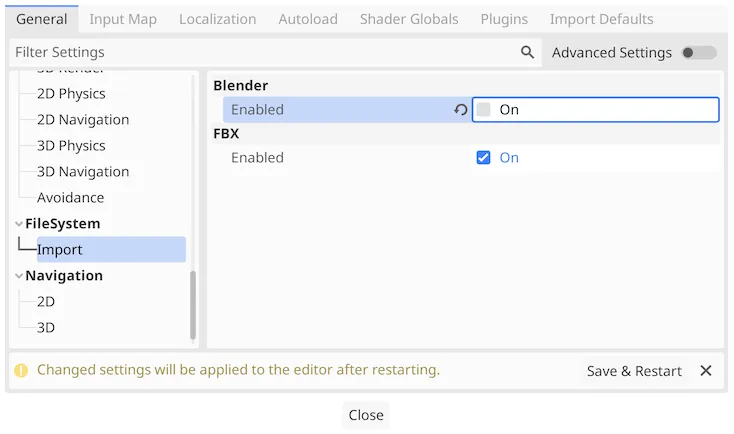
The window notifies us that this setting will take effect after restarting the editor. You can verify this by clicking Save & Restart. After the project is opened again the Blend file warning will not be logged.
What does the circular arrow next to the option mean?
It indicates the the value has been changed. Clicking it will set it back to its default value.
Creating a Scene
Now that we have a project open in Godot, have selected a theme to our liking, and have gotten rid of the warning, it is time to create something. But before we can start to build our clock we have to get familiar with the concept of scenes.
In Godot things are not created in a vacuum, everything is contained in a scene. A scene is typically thought of as either a place where something happens, like a movie scene, or a view of something, like a picture. In the case of Godot a scene could have either or both, it's a container for anything.
We will create a single scene for our clock.
Root Node
There must always be an open scene, which is shown in the viewport. As we haven't created a scene yet the tab of the current viewport displays [Empty]
.
A valid scene requires a root node. The panel to the left of the viewport, known as a dock, contains a Scene tab that currently asks us to create a root node, offering four options: 2D Scene, 3D Scene, User Interface, and Other Node. We're going to make a 2D clock, so create a 2D scene.
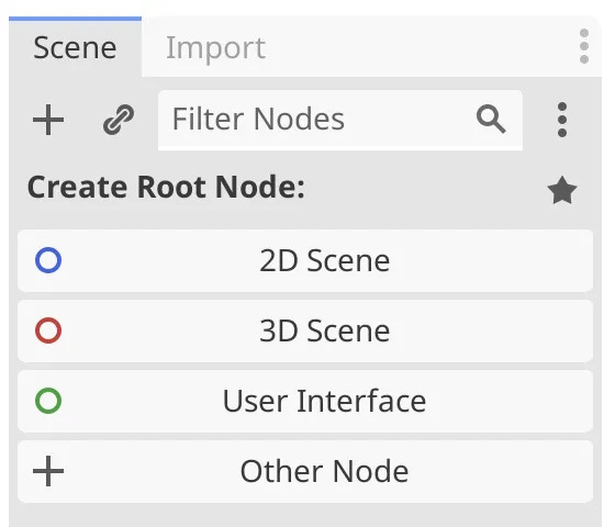
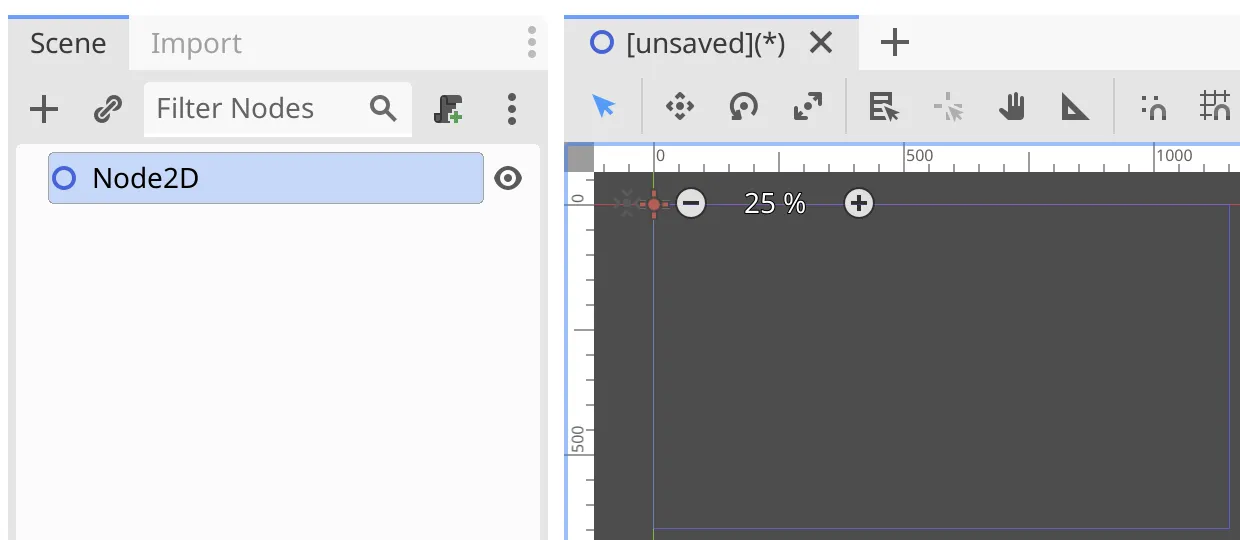
This does a few things. First, the root node options are replaced by a node list, containing a single Node2D
item. Second, the viewport switched from 3D to 2D. This is obviously visible in the viewport itself, and also by the selection change at the top of the editor. Third, the scene's tab has been renamed to [unsaved]
, with (*)
appended to it to indicate that it has changes that haven't been saved yet.
Node2Droot node.
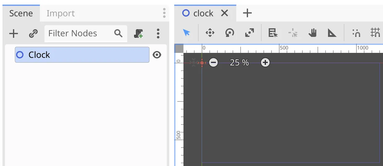
Node2D
is the root node of our scene. The default name of a node is its type name. Because it will represent a clock let's give it an appropriate name. Renaming a node is done by pressing the RETURN key while it is focused, or by double-clicking it, or by picking Rename from its context menu. Change its name to Clock
.
We could name nodes however we want, but Godot's convention is to capitalize them and not use spaces. This is known as PascalCase.
How do you open a context menu?
You do that by right-clicking or alternative-clicking on something. What you click defines the context of the menu that pops up. Not everything has a context menu.
Saving the Scene
To persist our work we have to save the scene. This can be done via the Scene › Save Scene main menu item or its indicated keyboard shortcut. This pops up a Save Scene As...
window with clock.tscn
already filled in. The convention is to not capitalize scene file names and not use spaces, so save it as it is.
What does TSCN mean?
It is the file extension and acronym for Godot's text scene file type. These files contain the data of a scene in text format, which is human-readable and works well with version control systems.
The scene file got saved in the project root folder, which is internally indicated with res://
. So the scene's file path inside the project is res://clock.tscn
. The project files can be browsed via the FileSystem tab, which sits in a panel at the bottom left of the editor.
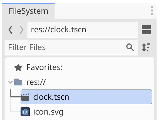
Besides our scene the project also contains the default Godot icon as an SVG image. The file system folder contains some more stuff, but that's internally used by Godot and not shown here.
Making the Clock Face
We're creating a standard round analog clock. The round background of the clock is known as its face. To build it we'll need to create a child node and some resources.
Child Node
A scene contains a hierarchy of nodes, forming a tree graph with its root node at the top. Nodes are the building blocks used to make things in scenes.
Our Clock
node is the root of the scene, containing everything in it. It is a Node2D, which means that it represents a 2D thing. We'll use a separate node to represent its face.
Open the context menu of the Clock
root node and pick the Add Child Node option, or use its indicated keyboard shortcut. This pops up a Create New Node
window.
Search for sprite2d
. That filters the node type hierarchy shown so we only see the portion that leads to Sprite2D.
What's a sprite?
It's slang for a small computer image, typically shown in a rectangular area that's positioned somewhere in the viewport and can be moved around.
sprite2dnode type.
This shows us that there is a generic root Node type, under which we find the CanvasItem type, under which there is the Node2D type. That's the type of our scene's root node. Node2D has multiple subtypes under it, including AnimatedSprite2D and Sprite2D. Select the latter and click Create or press the RETURN key to create the node.
We now have a second node in our scene, listed as a child of the root node. It's name is its type, but let's rename it to Face
.
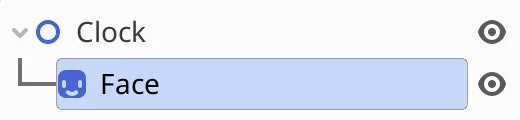
Facechild node of
Clock.
The dock to the right of the viewport contains three tabs, one of which is Inspector. It shows the configuration options for the currently selected node, which should be Face
. As our node is a Sprite2D the properties of that type are shown at the top. Below that are shown the properties of its other types, going back through the type hierarchy from specific to generic. So first Sprite2D, then Node2D, then CanvasItem, and finally Node.
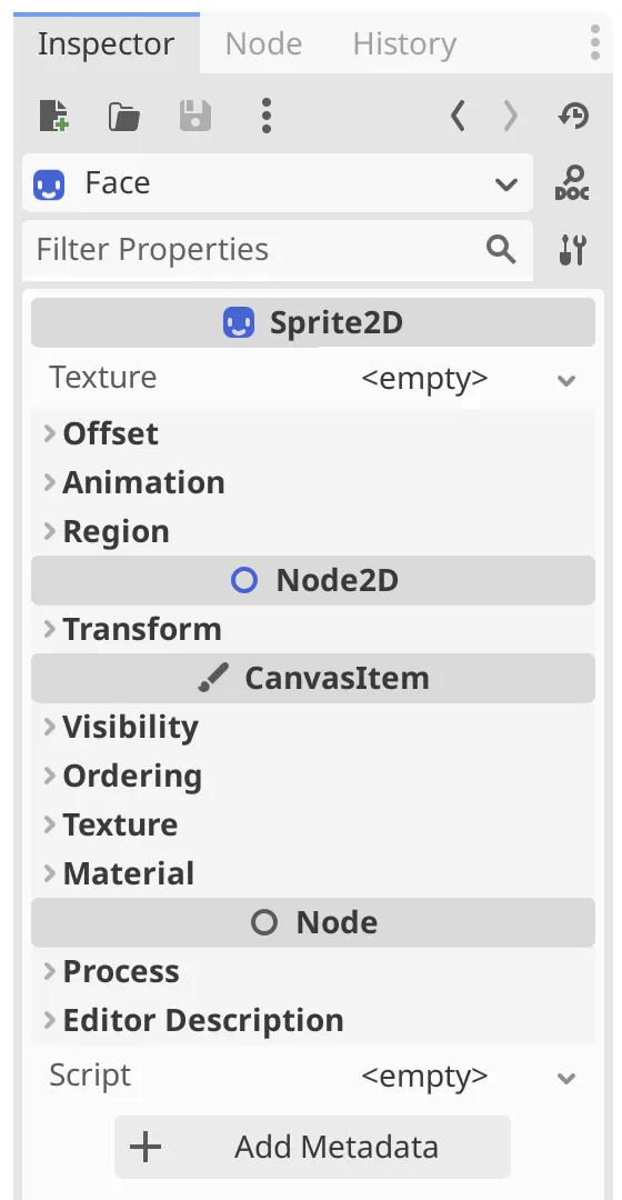
The properties are collapsed by default, indicated by the arrow icon on the left of each option, pointing right. Clicking the option expands or collapses it. When expanded the arrow icon points down. Many hierarchies in the editor can be collapsed or expanded.
Note that there is an icon to the right of Face
at the top of the inspector, looking like a magnifying glass with the word Doc
below it. Clicking it will open the in-editor documentation for the node's type in the viewport. That switches the viewport to Script mode. You can change it back to 2D mode via the options shown at the top of the editor.
Texture Resource
Our sprite is current invisible because it doesn't have any image data. Our clock face is a Sprite2D and thus has a Texture property. The term texture can refer to many surface properties, but in this case it only refers to its visual appearance.
The sprite currently has no texture, showing <empty>
for its value. The value is a dropdown menu, which can be expanded by clicking the downward-pointing arrow to the right of it. Doing so opens a list of options, from which we pick New GradientTexture2D.
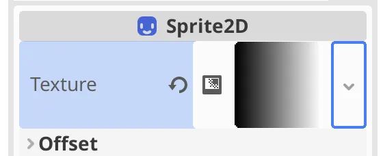
This has created a 2D gradient texture resource, a GradientTexture2D, which is stored in the scene. Resources are bits of data that can be shared between nodes. In this case we got a linear horizontal gradient that goes from black on the left to white on the right. Our sprite has also become visible in the viewport, displaying the gradient in a rectangle. You can pan around and zoom the viewport by dragging and scrolling or pinching, in combination with holding various buttons, to get a better look at it. The editor behavior can be adjusted via Editor › Editor Settings.. › Editors › Panning and the Shortcuts tab.
The default gradient doesn't look like a clock at all. To configure it, click the gradient itself. This expands its options. Alternatively, select the texture resource from the dropdown list at the top of the inspector, replacing Face
.
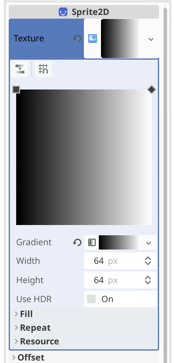
Let's first make the sprite bigger, by increasing both Width and Height to 256. This gives us a 256×256 texture, containing 65.536 color data points known as pixels. Our sprite will resize to match.
Why 256?
Computers internally use binary data, meaning that they naturally works with base 2 numbers, instead of the base 10 numbers that we normally use. This means that it's most convenient to work with powers of 2. For example, 64 is 26 and 256 is 28.
Using powers of 2 isn't strictly necessary, but it is a good rule of thumb to always use them for textures to be efficient and avoid some weird corner cases.
Our clock is supposed to be round. Under Fill, change Fill to Radial. Its From property is a 2D position with X and Y coordinates. X is the horizontal and Y is the vertical coordinate, going from 0 to 1. Set both to 0.5 so the gradient starts at the center of the texture. Then give To coordinates 1 and 0.5.
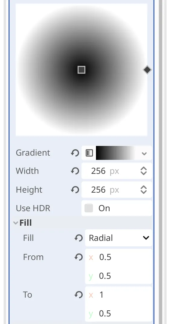
At this point we have a radial gradient, but it doesn't look like a clock face yet. We'll turn it into a simple solid white clock face by making part of the texture transparent.
Gradient Resource
Our texture's Gradient is a resource as well, of type Gradient. Expand it, or select the Gradient resource from the inspector's dropdown menu.
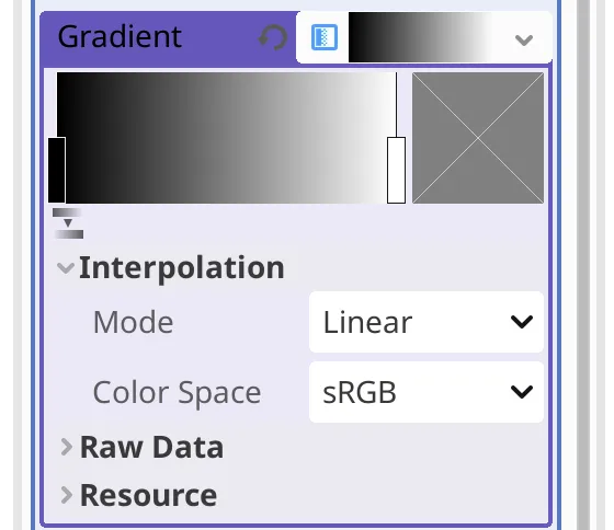
We have a default linear gradient in sRGB color space, which is fine. We only have to change its two color keys, which are displayed as vertical bars on top of the gradient. Selecting one shows its solid color to the right of the gradient. Double-clicking it pops up a color picker for it. Do this for the black key and change it to white.
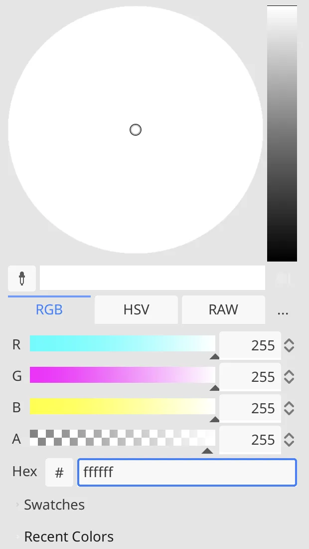
Regardless of the color picker's display mode, colors are defined by a combination of red, green, and blue components. Each has a value in the 0–255 range, which in hexadecimal notation is 0–ff. You can set it to white by typing ffffff in its Hex field.
What does the # button do?
Clicking it toggles between hex notation and RGB function rotation.
Both color keys are now white. But colors also have an fourth component, known as alpha, which is used to control transparency. Select the key on the right of the gradient and set its A component to zero. Alternatively, type ffffff00 in its Hex field.
This gives us a solid white texture that linearly fades out. To turn it into a solid disk drag the left key to the right until both keys almost entirely overlap. This can be done more precisely by expanding Raw Data, then expanding Offset by clicking its PackedFloat32Array and setting its first element to 0.98.
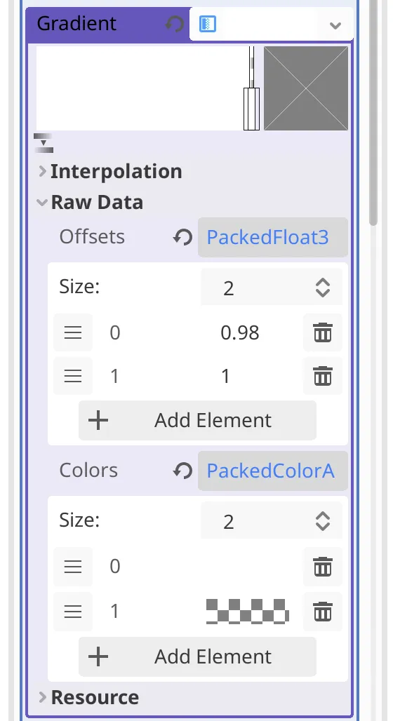
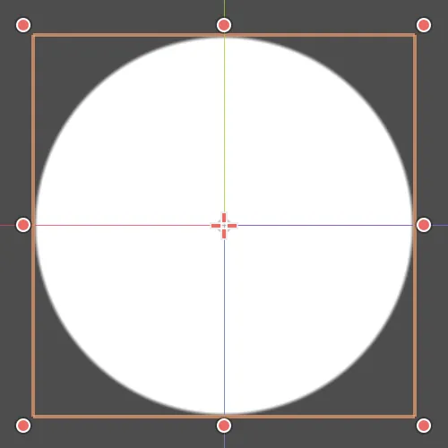
Our sprite now looks like a solid white disk, which is a fine face for a simple clock. It has a slightly fuzzy edge where it transitions from opaque to transparent across a few pixels.
Could we get rid of the fuzzy edge?
Yes, by setting the gradient's interpolation mode to Constant. But that won't look as good. The harsh transition will give the face a jagged edge. We could also use a completely different approach to draw a circle, but that's more complicated and not part of this tutorial.
Adding Hour Indicators
A solid white face could suffice for a minimal clock, but usually the face contains indicators to make reading the time easier, one per hour. These could explicitly display the hour numbers, but we'll use simple wedges.
Polygons
Rather that using a sprite again, we use a different approach to create an hour indicator. Add a child node to Face
, selecting the Polygon2D node type. Rename it to Hour0
. We don't put a space between Hour
and 0
to stick to Godot's PascalCase naming convention for nodes.
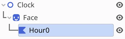
Hour0child node of
Face.
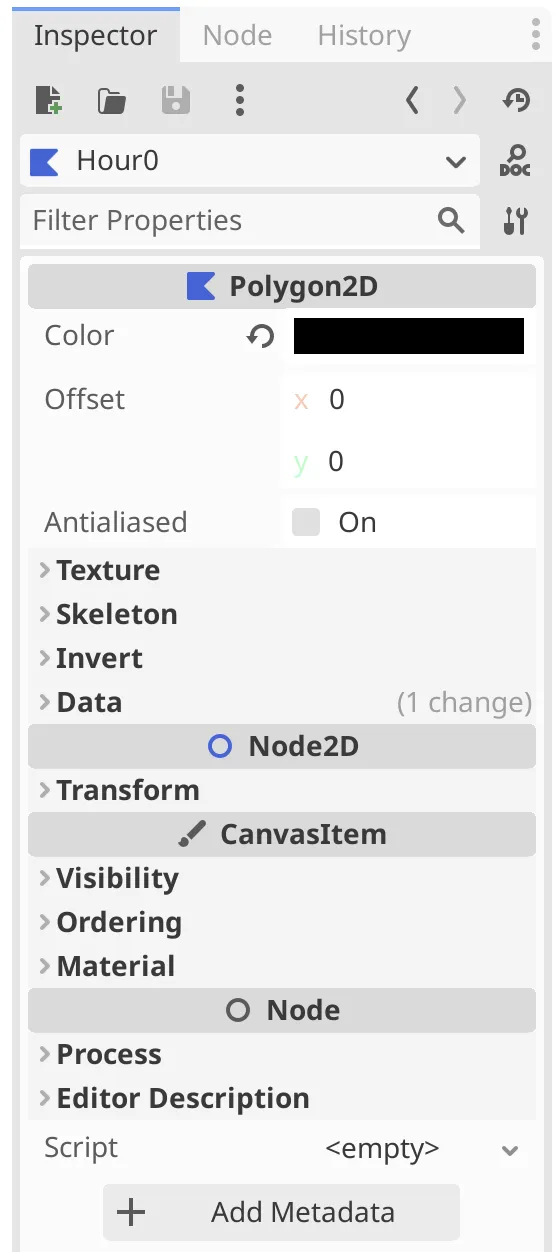
As a Polygon2D our node has a Color property. Set it to black, hex 000000.
The polygon is initially empty and invisible. It is formed by placing a sequence of points in the viewport. Tools for that show up in the viewport toolbar when a Polygon2D is selected.


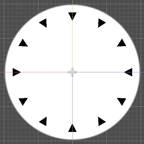
We're going to create a small downward-pointing triangle at the top of the clock face. To do so, first make sure that Select Mode is active, which can be done via the leftmost toolbar button that looks like a pointer. Also enable Use Grid Snap, via the button that looks like grid with a small horseshoe magnet. This turns on a grid that makes our points snap to increments of 8 pixels by default. The grid can be configured via the toolbar button with three vertical dots.
Place three points to form the triangle in a 16×16 area, 16 pixels below the top of the face sprite. After placing the points you can close the polygon by clicking on the first point or by pressing the RETURN key. If a point is in the wrong place you can move it to the correct position by dragging it.
We now have our first hour indicator. Because it is a child of the face it is draw on top of the disk. Parent nodes are drawn first, then their child nodes, from top to bottom as they are ordered in the scene hierarchy.
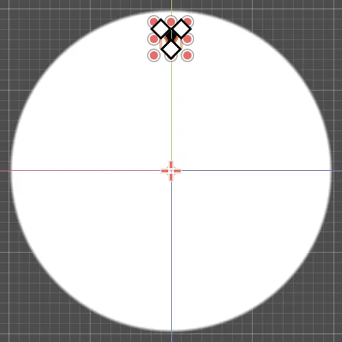
Make sure that the polygon's position is at the center of its parent. You can verify this by checking the small cross icon in the viewport that shows its pivot point. It should be in the center of the disk. You can also verify that its Node2D › Transform › Position property is set to zero for both X and Y.
If the polygon is misplaced move it to where it should be and adjust its points by dragging them if needed. You can undo and redo actions via the Scene › Undo and Scene › Redo menu items or their keyboard shortcuts.
Many operations have keyboard shortcuts. I will no longer point out that they exist.
Twelve Hours
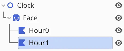
We create the other eleven hour indicators by duplicating and rotating the first one. Via its scene context menu, Duplicate Hour0
. This creates a clone of the node and places it underneath the original. The duplicate has been automatically renamed to Hour1
.
Currently the two indicators overlap. To move Hour1
to the next hour set its Node2D › Transform › Rotation property to 30. This makes the node rotate 30 degrees clockwise around its pivot point, 30° for short.
Why 30°?
Rotations are defined as degrees, with 360 describing a full circle. The number 360 was picked a long time ago, probably related to the Babylonian calendar that had 360 days per year.
As an analog clock displays twelve hours, there is a rotation angle of 360 divided by 12 per hour, which is 30°.
We can also rotate by switching the viewport to Rotate Mode, via the third toolbar button from the left that looks like an arrow curving around a point. Then dragging anywhere in the viewport will perform a rotation. By holding down CONTROL after starting rotating it snaps to 15° increments by default.
Keep duplicating and rotating the hour indicators until we have all twelve. Using keyboard shortcuts and snapping rotation mode is a convenient way to do this.
Is this an efficient way to draw the indicators?
No, but it is simple and suffices for our purposes.
Clock Arms
In order to display the time our clock needs arms, one for the current hour, one for the current minute, and one for the current second.
Hour Arm
We'll also use Polygon2D nodes to create the arms. Either create a new one or duplicate Hour0
and change its name to HourArm
. The arm isn't part of the face so make it a direct child of Clock
if it isn't already. You can change its parent and position in the scene hierarchy by dragging it, or via its Reparent and Move Up and Move Down context menu items to have more precise control.
HourArmchild node,
Facehierarchy collapsed.
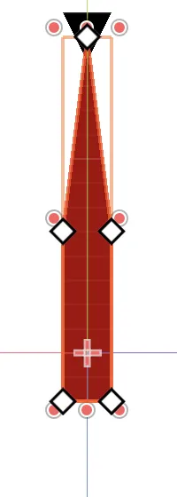
Make sure that the viewport is in Select Mode, then create a simple short thick arrow pointing at the Hour0
indicator, using five points. If you started with a duplicated hour indicator you can drag the nodes to reposition them and add new ones by clicking the polygon edges in between points.
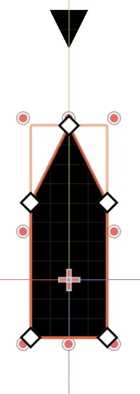
Make the arrow overlap its pivot point so it appears to have a counterweight when rotating. This gives is a little visual balance. Make it one step wider than the hour indicators.
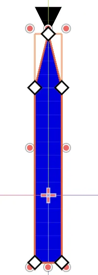
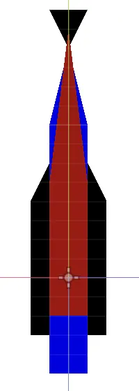
Minute and Second Arms
Duplicate HourArm
and name it MinuteArm
. Make it a longer and narrower arrow, with its tip touching Hour0
. Also give it a different color. I used slightly darkened blue, hex 0000e5. You can temporarily hide the hour arm by clicking the eye-like icon next to it in the scene hierarchy. Then do the same for a SecondArm
, giving it a sharper point that overlaps Hour0
and has a smaller counterweight. I colored it red, hex a50000.
Of course you can design your clock arms in a different way, but this is the reference design for the tutorial.
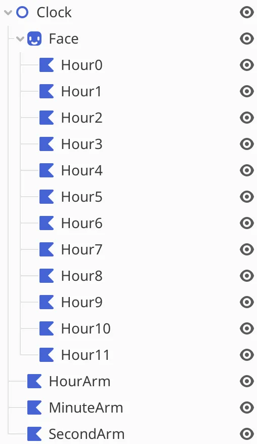
Our clock hierarchy is now complete. It has a face with hour indicators and three arms to show the time.
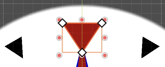
Special Hour Indicator
We used Hour0
as a reference point for designing our arms, but now that we're done with that let's give it a slightly difference appearance. By making the zero or twelfth hour stand out it is easier to tell the time, especially when the clock itself is rotated. Make it one step larger, dragging its points left, right, or down. I also gave it the same color as SecondArm
.
Running the Scene
With our clock design complete let's see how it looks when running it as a stand-alone app.
Running the Current Scene
We can instantly run a debug version of it by clicking the Run Current Scene button in the toolbar at the top right of the editor, which looks like a movie clapperboard with a play icon.

After a short delay this opens a separate app showing our scene. Its title bar contains our project name with (DEBUG)
added to indicate that it is running in debug mode.
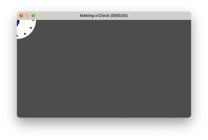
Quit the app, either the normal way or by pressing the stop button in the editor toolbar.
Repositioning the Clock
Currently our clock is stuck in the top left corner of the window, so we only see its bottom right quadrant. The top left corner is the origin of the scene's viewport. The scene viewport rectangle is shown in the editor viewport as a dark purple rectangle. Its size is configured via Project › Project Settings... › Display › Window, where you can see and adjust Viewport Width and Viewport Height.
The default viewport size is 1152×648 pixels. Let's keep that size and put our clock in the center, by setting the Transform › Position of our Clock
root node to X 576 and Y 324. As children are positioned relative to their parent all child nodes will move along with it.
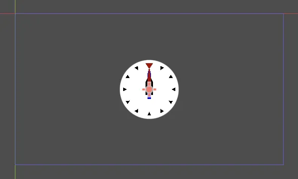
I cannot see the viewport rectangle, where is it?
It has low opacity by default, which makes it hard to see on top of the axis lines and the standard gray viewport background. You can change its line color via Editor › Editor Settings... › Editors › 2D › Viewport Border Color.
If we run our scene now the clock will show up in its center.
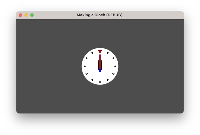
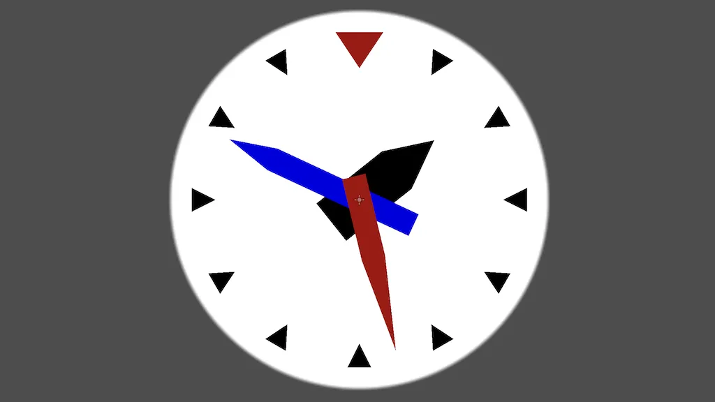
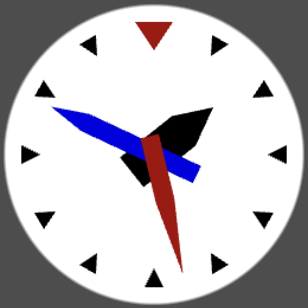
Setting a Time
We will program our clock to display the time in the next tutorial, but we can already set it to a fixed time by rotating its arms. For example, I set it to indicate roughly 01:49:27.
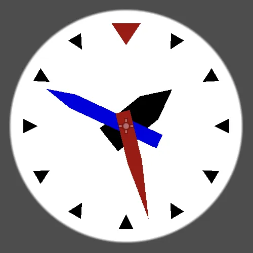
Anti-Aliasing
You may have noticed, while in the editor or while running the scene, that the hour indicators and arms have jagged edges. That's because the polygons have sharp edges. This is more obvious when zooming in.

This visual appearance is caused by the limited pixel resolution of the display and is commonly known as aliasing. It can be especially obvious when things are in motion.
To combat these visual artifacts let's turn on MSAA, in the project settings window, under Rendering › Anti Aliasing. Set MSAA 2D to 4x (slow), which is the typical setting used for MSAA.
What is MSAA?
MSAA is an acronym for Multisample Anti-Aliasing. It is a special form of supersampling that can smooth out hard geometric edges, but not textures. MSAA 4x behaves somewhat like rendering at double resolution and scaling down the result, averaging adjacent pixels. That's an oversimplification, but gives you an idea of what it does.
Although the editor indicates that it is slow, MSAA 4x is often a fair trade-off between rendering speed and quality. It offers a significant visual improvement for our clock scene. You could also experiment with different anti-aliasing options.
The next tutorial is Programming a Clock.