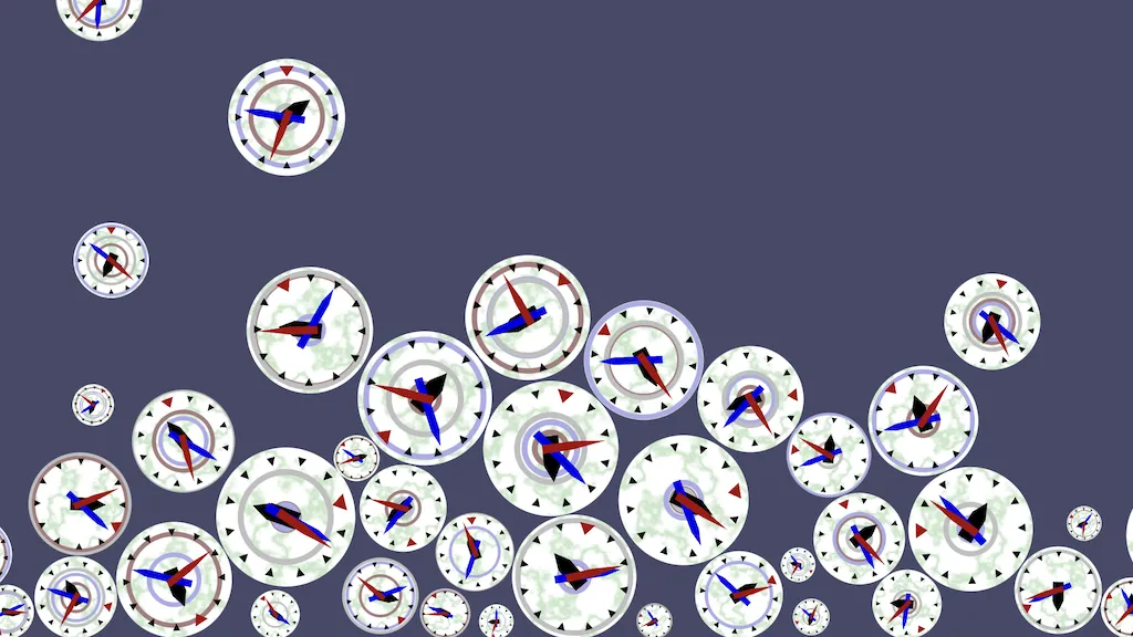
Clocks With Rings
This is the fourth tutorial in a series that introduces you to the Godot Engine, version 4. It follows Many Clocks, customizing the clock face with a custom shader. Like with the previous tutorial, you can either continue working in the same project, make a duplicate project, or download the repository.
This tutorial is made with Godot version 4.2.1. The previous ones were made with 4.1 so opening those in 4.2 will show a popup window asking for confirmation to upgrade the project. The upgrade can be done without issues.
Coloring Clocks
When we spawn many clocks they all look exactly the same. Only their size and the time that they display varies. We're going to add a little variation to this.
Color Modulation
One simple way to customize our clock is to give it a different color. Our clock's Visualization
node has a CanvasItem › Visibility property group that offers two ways to modulate its color.
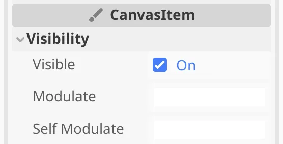
The Modulate property is a color that is multiplied with the sprite's texture color, acting like a filter. It applies to the sprite itself and also to all its child nodes, applying a tint to the entire clock. The Self Modulate property does the same except that it only applies to the node itself. We'll use the second option so the clock arms aren't affected.
Random Colors
We can set the Self Modulate color via our clock.gd
script by assigning a Color to visualization.self_modulate. Let's set it to yellow at the end of _ready(), using the Color.YELLOW constant.
func _ready() -> void:
	if start_time == StartTimeMode.RANDOM_TIME:
		seconds = randf_range(0.0, 43200.0)
	else:
		…
	visualization.self_modulate = Color.YELLOW
We can also construct a color ourselves by invoking Color as a constructor function with three arguments, which are the red, green, and blue color components. Regular colors are made with values in the 0–1 range. Colors also have a fourth alpha component that controls opacity, which is set to 1 by default if we do not provide a fourth argument. Yellow is made by setting the red and green color components to 1 and blue to 0.
visualization.self_modulate = Color(1.0, 1.0, 0.0)We can turn this in a random color between pure yellow and white by using randf() for the blue component.
visualization.self_modulate = Color(1.0, 1.0, randf())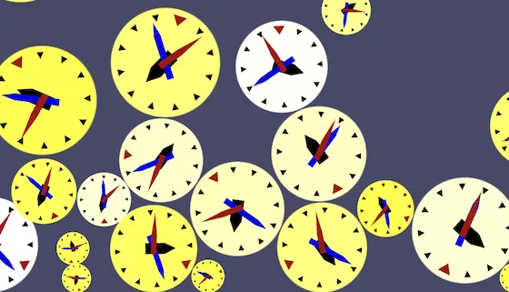
And if we make all RGB components random we get arbitrary colors.
visualization.self_modulate = Color(randf(), randf(), randf())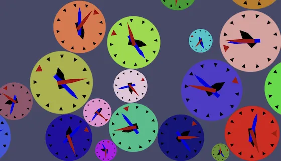
HSV Colors
Fully random RGB colors are often ugly, clash with each other, and can make the clock hard to read. An alternative is to construct the color using the HSV format, which stands for hue, saturation, and value. Godot's color picker popup window also allows this format to construct colors, though the final values will always be RGB.
To construct a color using HSV components we can use Color.from_hsv().
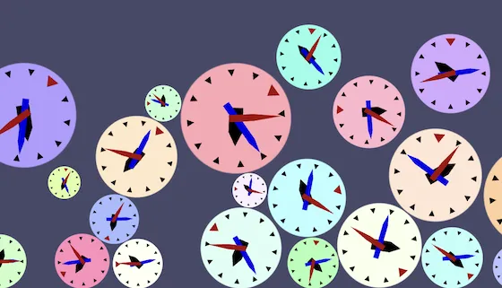
visualization.self_modulate = Color.from_hsv(randf(), randf(), randf())Now we can limit some of the components to generate a more pleasing color palette. Let's fix value at 1 so all colors are bright. Let's limit saturation to the 0–0.5 range so the colors will be fairly desaturated, tending toward white. Hue stays fully random so we can cover the entire color spectrum.
	visualization.self_modulate = Color.from_hsv(
			randf(),
			randf_range(0.0, 0.5),
			1.0
	)
Coloring With Time
Another possibility is that we modulate the clock's color based on its time. First remove the fixed color modulation from _ready().
func _ready() -> void:
	…
	#visualization.self_modulate = Color.from_hsv(
			#…
	#)
Then set the clock's hue based on its current second, or more specifically the orientation of its second arm. To get that in the 0–1 range we need the rotation value that we calculate for it in _process() without the multiplication with TAU. Rather than performing that calculation twice let's extract that portion and store it in a variable that we simply name s.
func _process(delta: float) -> void:
	seconds += delta * time_scale
	var s := fmod(seconds, 60.0) / 60.0
	second_arm.rotation = s * TAU
	minute_arm.rotation = fmod(seconds / 60.0, 60.0) * TAU / 60.0
	hour_arm.rotation = fmod(seconds / 3600.0, 12.0) * TAU / 12.0
Now we can use s for the hue and let's set saturation and value to 0.25 and 1.
func _process(delta: float) -> void:
…
hour_arm.rotation = fmod(seconds / 3600.0, 12.0) * TAU / 12.0
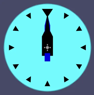
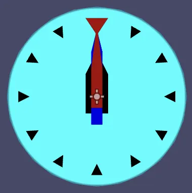
visualization.self_modulate = Color.from_hsv(s, 0.25, 1.0)How did you keep the clock in place?
I temporarily set the clock's Rigidbody2D › Gravity Scale to zero and ran the clock
scene with its Time Scale set to 10.
Custom Shader
Modulating the color of a sprite is only the simplest way to adjust our clock's visualization. It is also possible to completely change how the clock's face gets rendered, by writing a custom shader.
New Material
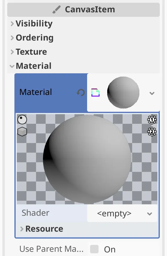
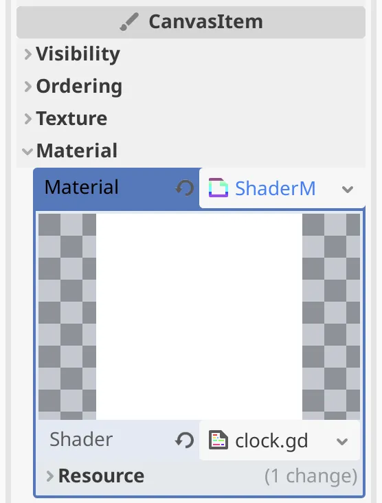
Before we can use a custom shader we must first give our clock a custom material. The CanvasItem › Material › Material property of the Visualization
node controls what material is used to render it. It is current empty, causing it to use the default sprite material. Create a material for it by picking the New ShaderMaterial option for this property. There is also an option for a canvas material, but that doesn't allow us to create a custom shader, so we pick the general-purpose option.
The material has a Shader property, which is empty so it uses the default shader. To create our own shader pick its New shader option. This opens a popup window that allows us to configure the kind of shader that we want. Set its Type to Shader, set Mode to Canvas Item, make Template empty, and save it as clock.gdshader
.
When we open the shader file it appears in the panel below the editor viewport, which switches to Shader Editor
mode. Our shader currently contains a single line, which declares that it is a shader of the type that we selected. This statement is explicitly terminated with a semicolon.
shader_type canvas_item;We'll use Godot's style guide for shader code, which is mostly the same as for GDScript, besides the syntax differences. The biggest difference is that there aren't two blank lines between functions.
Note that the shader syntax highlighting shown in this tutorial is a bit more advanced than the one used by Godot. For example the Godot editor styles global functions the same as regular keywords.
Could we also create a visual shader?
Yes, both versions can produce the same results, but code is easier to structure and explain in a written tutorial.
Fragment Function
Our shader is a program that tells the GPU how to render the clock face. As we currently don't override the default functionality it acts as a normal sprite shader. To change its behavior we define a custom fragment() function, which returns nothing. The shader syntax is different than GDScript and resembles GLSL. Instead of starting a function definition with func we start with its return type, which is void in this case, followed by the function name and its parameter list.
shader_type canvas_item;

void fragment()
The scope of the code block of the function has to be explicitly indicated by enclosing it with curly brackets instead of with a colon.
void fragment() {}In this case a fragment represents a pixel that gets covered by the rectangular sprite of our clock face. To change how it looks we have to assign something to the built-in COLOR variable. The shader language is more low-level than GDScript, so we have to construct a generic four-component vector value rather than an explicit color. In this case the type is vec4. Let's once again start with fully opaque yellow.
void fragment() {
	COLOR = vec4(1.0, 1.0, 0.0, 1.0)
}
Unlike with GDScript we have to explicitly terminate all statements with a semicolon.
COLOR = vec4(1.0, 1.0, 0.0, 1.0);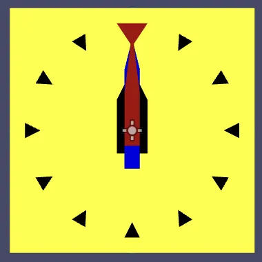
Now that we override the default color of the fragment the entire sprite has become yellow and thus our clock appears as a square. We'll restore its roundness later.
UV Coordinates
By default the shader samples the texture of the sprite, using the texture coordinates of the fragment. These are accessible via the TEXTURE and UV variables. The texture coordinates are known as UV coordinates because they are 2D coordinates typically referred to as U for the horizontal dimension and V for the vertical dimension. To sample the texture ourselves we can use the texture() function, passing it the texture and its coordinates.
COLOR = texture(TEXTURE, UV);We can also visualize the texture coordinates themselves by using them to create a color. For example, by using the U coordinates to create a red tint. UV coordinates are of type vec2. Its first component is accessed via UV.x.
COLOR = vec4(UV.x, 0.0, 0.0, 1.0);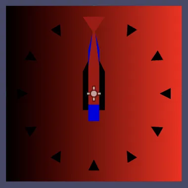
The U coordinate goes from left to right and covers the 0–1 range. The V coordinates goes from top to bottom. To use the V coordinate for the green color component we could access UV.y, or we can use a variant of the vec4 constructor function that takes a vec2 as its first argument.
COLOR = vec4(UV, 0.0, 1.0);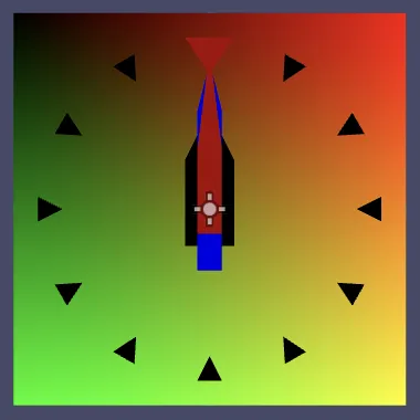
Note that these coordinates are relative to the sprite. They scale and rotate along with it.
In general there are up to four vector components to access, depending on the vector type. They are known as X, Y, Z, and W. It is also possible to use R, G, B, and A, which are aliases used by convention when interpreting vectors as colors.
Clock Radius at Fragment
We can use the UV coordinates to figure out the face radius at the fragment, which is its distance from the clock's center. We start by declaring a variable of type float named radius. Just as with functions we don't use the var keyword but instead start with the variable's type.
void fragment() {
	float radius;
	COLOR = vec4(UV, 0.0, 1.0);
}
We then initialize the color to uniform white using the vec4 constructor with a single value. After that we multiply the RGB components with the radius to visualize it. We can do this in a concise way by extracting the RGB components as a vec3 using COLOR.rgb. Then multiply that vector with the radius and assign it back to COLOR.rgb. Manipulating vector components like this is known as swizzling.
	float radius;
	COLOR = vec4(1.0);
	COLOR.rgb *= radius;
The UV coordinates describe a vector pointing from the sprite origin to the fragment. We can get its length by passing it to the length() function.
float radius = length(UV);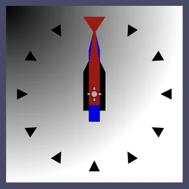
This gives us the distance from the top left corner of the sprite. The UV coordinates of the sprite's center are both 0.5, so if we subtract that from the UV coordinates we get the distance from the center.
float radius = length(UV - vec2(0.5));Alternatively, we can use the distance function and pass it the fragment's and center's coordinates, which does the same thing.
float radius = distance(UV, vec2(0.5));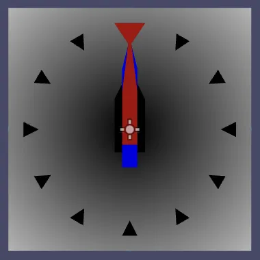
Let's normalize the radius so it's 1 at the circular edge of the clock face. It's currently 0.5 at the edge, so we have to double it. I added a code comment line to describe what radius represents. Shader comment lines are started with two slashes.
	// Clock radius at fragment, normalized so it is 1.0 at its face edge.
	float radius = 2.0 * distance(UV, vec2(0.5));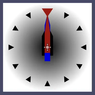
Stepping
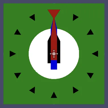
We can use the face radius at the fragment to split the sprite in two regions: one below and one above a given threshold. For example, let's use an if block to make the sprite green where the radius is greater than 0.5, using a comparison check.
	COLOR = vec4(1.0);
	//COLOR.rgb *= radius;
	if (radius > 0.5) {
		COLOR.rgb = vec3(0.0, 0.5, 0.0);
	}
Instead of making a binary choice we can mix colors using the mix() function. It has three parameters: two colors and a float that controls how they are mixed. The mixer value is supposed to be in the 0–1 range and linearly interpolates from the first to the second color. If we set the mixer to either 1 or 0 based on the radius via a mixer variable we get the same result as before.
	COLOR = vec4(1.0);
	float mixer;
	if (radius > 0.5) {
		mixer = 1.0;
	}
	else {
		mixer = 0.0;
	}
	COLOR.rgb = mix(COLOR.rgb, vec3(0.0, 0.5, 0.0), mixer);
We can shorten this simple if-else code to a single expression using the ternary operator, which is of the form condition ? true_result : else_result.
	float mixer = radius > 0.5 ? 1.0 : 0.0;
	//…
	COLOR.rgb = mix(COLOR.rgb, vec3(0.0, 0.5, 0.0), mixer);
Because stepping over a threshold to get either 1 or 0 is a common thing, we can also use the step() function, passing it the threshold and the value to check.
float mixer = step(0.5, radius);Smooth Stepping
Currently the edge between the white and green region is sharp and aliased. MSAA doesn't mitigate this because it only affects the edges of geometry and not what gets rendered inside it. We can smooth the transition by switching to the smoothstep() function. This function requires a second threshold and spreads the transition out between both. So the result is a value in the 0–1 range. Let's use this to smoothly mix the colors between radius 0.5 and 0.6.
float mixer = smoothstep(0.5, 0.6, radius);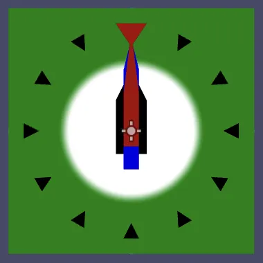
What is the smoothstep() transition function?
The function used is 3x2−2x3 clamped to 0–1. We can temporarily visualize it using the UV coordinates. For example, using step with U as the threshold and V as the value produces a straight downward diagonal split.
COLOR.rgb = vec3(step(UV.x, UV.y));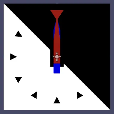
If we then apply smoothstep to U and stretch the transition across the entire 0–1 range we can see how the smooth transition is shaped.
COLOR.rgb = vec3(step(smoothstep(0.0, 1.0, UV.x), UV.y));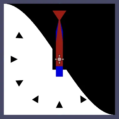
Screen-Space Derivatives
Although this approach smoothes, the transition region is fixed relative to the sprite's size. To perform proper anti-aliasing the smoothing range should depend on the fragment's size. For example, assuming that our sprite is displayed at its actual size each fragment covers one of the pixels of the 256×256 texture. A smoothing region that is one pixel wide could be created by using a blend region that is as long as the inverse of 256. We could either center it on 0.5 or make it extend in one direction. Let's do the latter, smoothing outward.
float mixer = smoothstep(0.5, 0.5 + 1.0 / 256.0, radius);To base this transition region on the size that the sprite is rendered at we can look at the screen-space derivate of the radius. This tells us how much the radius changes between adjacent fragments. We can then simply use that as the smoothing region's size.
As we render to a 2D viewport there exists a derivative in both dimensions. Let's begin by only considering the horizontal derivative. We can find it by passing the radius to the dFdx() function. To make it clearly visibily let's overestimate it by a factor of 50, scaling the radius we pass to it by that amount.
float mixer = smoothstep(0.5, 0.5 + dFdx(50.0 * radius), radius);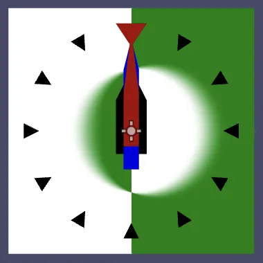
This shows us that indeed we get horizontal smoothing, but the results are inverted on the left side of the sprite. This happens because the derivative is negative on that side. If the second threshold of smoothstep() is smaller than the first the result gets inverted. We fix this by taking the absolute derivative, passing it through the abs() function.
float mixer = smoothstep(0.5, 0.5 + abs(dFdx(50.0 * radius)), radius);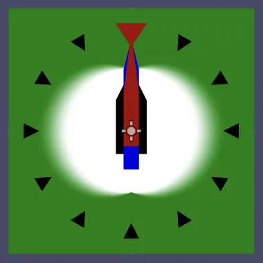
We can do the same for the vertical derivative by using dFdy() instead. For the final smoothing we need to use both. For best results we could interpret the 2D derivative as a vector and calculate its length, however we can suffice with using the fwidth() function instead. This function gives us the sum of the absolutes of both derivatives.
float mixer = smoothstep(0.5, 0.5 + fwidth(50.0 * radius), radius);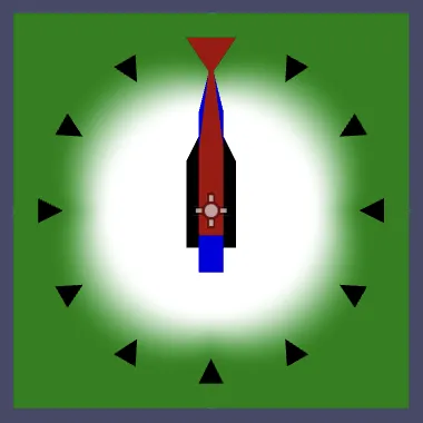
The result overestimates the diagonal change, but that's fine because the edge needs more smoothing there anyway. For single-pixel smoothing we simply use the unscaled radius. But let's make it a little bit smoother than that by stretching it across 1.5 pixels.
float mixer = smoothstep(0.5, 0.5 + fwidth(1.5 * radius), radius);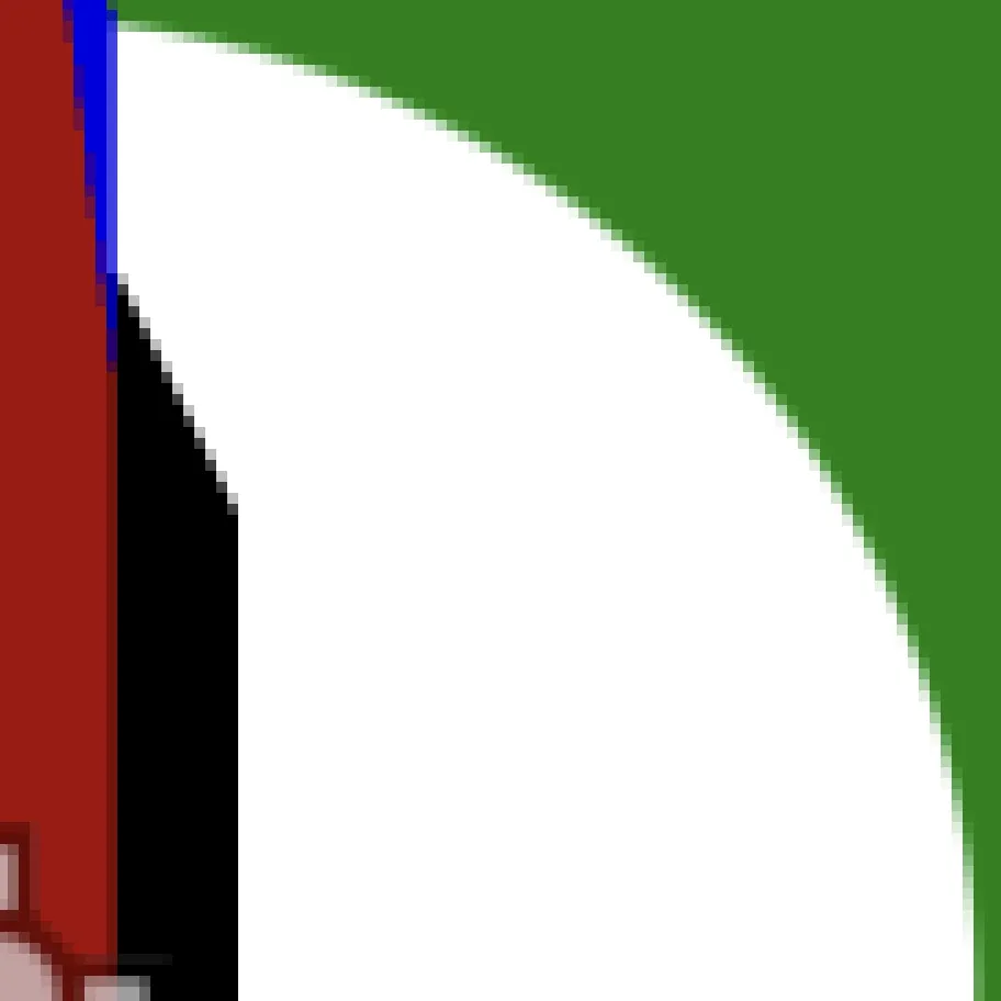
Creating a Ring
Let's extract the code to calculate the mixer value and put it in its own function for easier use, which we name smooth_above(), with parameters for a threshold and a value. Like with function and variable declarations we have to write a parameter's type in front of its name. Shader code is very strict about declaring things before they are used, so we have to define it above the fragment() function.
float smooth_above(float threshold, float value) {
	return smoothstep(threshold, threshold + fwidth(1.5 * value), value);
}

void fragment() {
	// Clock radius at fragment, normalized so it is 1.0 at its face edge.
	float radius = 2.0 * distance(UV, vec2(0.5));
	COLOR = vec4(1.0);
	float mixer = smooth_above(0.5, radius);
	COLOR.rgb = mix(COLOR.rgb, vec3(0.0, 0.5, 0.0), mixer);
}
Let's also declare the smoothing factor as a constant above the function, to make it easier to change. That's done like declaring a variable but with const written before it.
const float SMOOTHING = 1.5;

float smooth_above(float threshold, float value) {
	return smoothstep(threshold, threshold + fwidth(SMOOTHING * value), value);
}
Now that we have a smooth_above() function let's also add a smooth_below() function, which goes in the opposite direction by subtracting the smoothing range instead of adding it.
float smooth_above(float threshold, float value) {
	return smoothstep(threshold, threshold + fwidth(SMOOTHING * value), value);
}

float smooth_below(float threshold, float value) {
	return smoothstep(threshold, threshold - fwidth(SMOOTHING * value), value);
}
We can use both to create a ring. Let's give the ring a thickness equal to 0.1 of the face radius. Introduce a constant for that.
const float RING_THICKNESS = 0.1;
const float SMOOTHING = 1.5;
Then add a get_ring_weight() function that gives the weight for a ring, given a start radius and the fragment's radius. The weight is the product of both our smoothing functions, with smooth_below offset by the ring's thickness.
float get_ring_weight(float start_radius, float radius) {
	return (
			smooth_above(start_radius, radius) *
			smooth_below(start_radius + RING_THICKNESS, radius)
	);
}
To add the ring we use that function to calculate mixer.
float mixer = get_ring_weight(0.5, radius);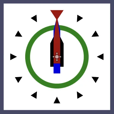
Round Face Edge
To once again make our clock round we could factor the texture into the result, but we now have a way to make a sharper anti-aliased face edge than what we could get by relying on our texture. Use smooth_below() with a threshold of 1 to set the color's alpha component at the end of fragment().
	COLOR.rgb = mix(COLOR.rgb, vec3(0.0, 0.5, 0.0), mixer);
	COLOR.a = smooth_below(1.0, radius);
Although we're no longer using the texture in the shader we still need it because Godot uses it to determine the sprite's size. We'll give it a new purpose later.
Animating Rings
While drawing the ring we ignored the color that we used to modulate the clock's face. Now we're going to combine both techniques to create animating rings.
Ring for Second Arm
Switch back to creating a regular RGB color in clock.gd
, using the s value for red and leaving the rest as is.
visualization.self_modulate = Color(s, 0.25, 1.0)This means that we're sending the progress of the second arm to the GPU via the sprite color, which suggests that we could retrieve it via COLOR.r in the shader. However, when we access COLOR in fragment() we get the sprite's texture modulated with the color, not the modulation color in isolation.
Sprites are drawn in the same way as polygons, like the hour indicators and arms. They're made by drawing a rectangle that has four corner points, which are known as vertices. These vertices contain data, including their position and also the modulation color.
To access the modulation color in isolation we have to retrieve the vertex color, then send that color to the fragment() function separately. That's done by declaring a global variable with the varying keyword in front of it in our shader. Let's declare such a float clock_data variable.
const float RING_THICKNESS = 0.1;
const float SMOOTHING = 1.5;

varying float clock_data;
It's described as varying because it can change across the surface of the sprite. If two vertices would have different colors it would get interpolated across the surface in between them. So a varying variable acts as a data channel from vertices to fragments.
In our case the color is the same for all vertices, so we'll always get the same color everywhere. Interpolation makes no difference. We can indicate this by also declaring clock_data to be flat. Instead of mixing the colors the GPU will simply pick one of the vertex colors.
varying flat float clock_data;To set our clock data we have to add a void vertex() function, which gets invokes once per vertex instead of once per fragment. In it COLOR refers to the pure vertex color, from which we can extract its red component and assign it to clock_data.
void vertex() {
	clock_data = COLOR.r;
}

void fragment() { … }
Now we can use the clock data for the start radius in fragment(). This will make the ring radius grow across the span of a minute and then reset back to zero.
float mixer = get_ring_weight(clock_data, radius);Don't we have to worry about color spaces?
Godot renders 2D graphics in gamma color space by default. As modulation colors are assumed to be in the same color space no conversions take place. 2D viewports can be set to use HDR rendering, in which case the RGB channels will get converted to linear space and you'd have to compensate for that to get the correct clock data in the shader. That's a downside of using the vertex color to store non-color data.
Three Rings
We can do this for the minute and hour arms as well. Change _process() so their progress values get stored in the green and blue channels.
	var s := fmod(seconds, 60.0) / 60.0
	var m := fmod(seconds / 60.0, 60.0) / 60.0
	var h := fmod(seconds / 3600.0, 12.0) / 12.0
	second_arm.rotation = s * TAU
	minute_arm.rotation = m * TAU
	hour_arm.rotation = h * TAU
	visualization.self_modulate = Color(s, m, h)
Then change clock_data to a vec3 and set all its components.
varying flat vec3 clock_data;

…

void vertex() {
	clock_data = COLOR.rgb;
}
Let's introduce a convenient add_ring() function that mixes a color with a ring color based on a start radius and the fragment's radius.
float get_ring_weight(float start_radius, float radius) { … }

vec3 add_ring(vec3 color, vec3 ring_color, float start_radius, float radius) {
	return mix(color, ring_color, get_ring_weight(start_radius, radius));
}
Invoke that function three times in fragment() to create the three rings, using dark shades of red, green, and blue for their colors.
	//float mixer = get_ring_weight(clock_data, radius);
	//COLOR.rgb = mix(COLOR.rgb, vec3(0.0, 0.5, 0.0), mixer);
	COLOR.rgb = add_ring(COLOR.rgb, vec3(0.5, 0.0, 0.0), clock_data.x, radius);
	COLOR.rgb = add_ring(COLOR.rgb, vec3(0.0, 0.5, 0.0), clock_data.y, radius);
	COLOR.rgb = add_ring(COLOR.rgb, vec3(0.0, 0.0, 0.5), clock_data.z, radius);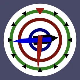
Ring Colors
It is possible to configure the shader via its material inspector, by adding uniform global variables to it. These are known as uniform because their values are the same for all fragments. Create such a vec3 second_color variable.
shader_type canvas_item;

uniform vec3 second_color;
This is supposed to represent an RGB color. To indicate this we can add a usage hint to it, by following the variable's name with a colon and source_color as a hint.
uniform vec3 second_color : source_color;We can also assign a default value to it, let's again use dark red.
uniform vec3 second_color : source_color = vec3(0.5, 0.0, 0.0);Declare variables for the minute and hour arms in the same way.
uniform vec3 second_color : source_color = vec3(0.5, 0.0, 0.0);
uniform vec3 minute_color : source_color = vec3(0.0, 0.5, 0.0);
uniform vec3 hour_color : source_color = vec3(0.0, 0.0, 0.5);
The material used by our clock's Visualization
node now shows color properties for these three values in a Shader Parameters section of its inspector. Let's adjust these properties so they're more interesting, for example a67c7c, acace6, and bfbfbf.
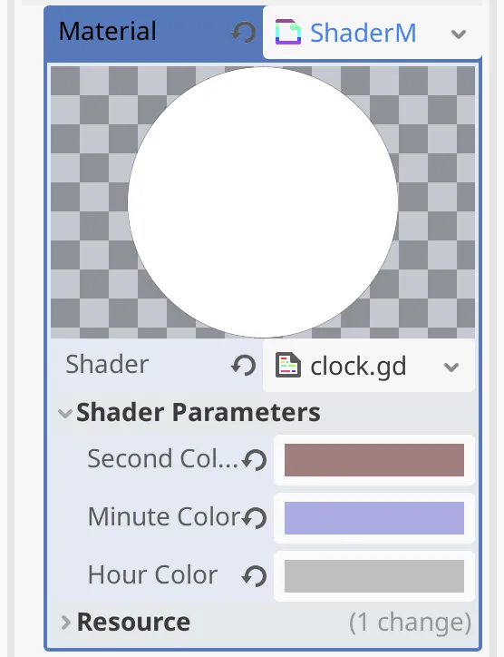
Use these colors for the rings in fragment().
	COLOR.rgb = add_ring(COLOR.rgb, second_color, clock_data.x, radius);
	COLOR.rgb = add_ring(COLOR.rgb, minute_color, clock_data.y, radius);
	COLOR.rgb = add_ring(COLOR.rgb, hour_color, clock_data.z, radius);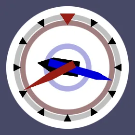
Can't we use uniforms to store the clock data?
That is possible, but less efficient. We'd have to create a unique material for each clock instance and adjust its properties each frame.
Face Texture
We finished our clock with animating rings, but we're left with an unused sprite texture. Let's put that texture to use again by projecting an image on the clock's face.
Face Texture
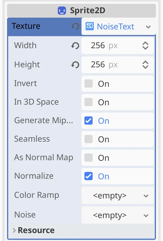
We could use any image for the face, but let's use a simple procedural texture. Replace the current circle texture of Visualization
by picking the New NoiseTexture2D option for its Sprite2D › Texture. This fully replaces the old resource. Again set both its width and height to 256.
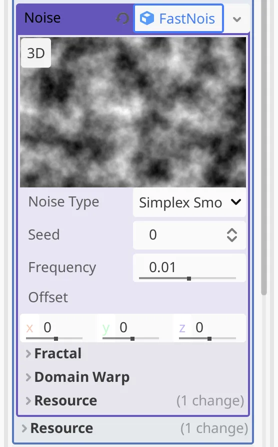
To generate a noise pattern we pick New FastNoiseLite for its Noise property. This gives us a new resource with configuration options for the noise. We can keep the default values. The result is a fractal-like grayscale pattern.
Adjust fragment() so it starts with the texture's RGB values before adding the rings.
	//COLOR = vec4(1.0);
	COLOR.rgb = texture(TEXTURE, UV).rgb;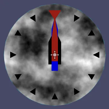
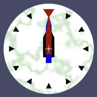
We can turn this grayscale pattern into something that resembles white marble by adjusting the Color Ramp of the noise texture. Set it to a gradient that has two white keys at 0.35 and 0.65, with another key in the middle at 0.5. I made that one light green, c5e6c5.
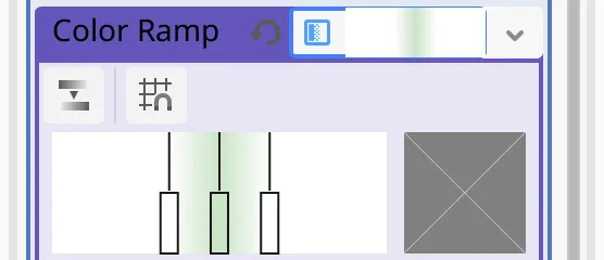
This keeps the clock face mostly white, but with a wiggly color band that somewhat resembles marble.
Mirrored Marble Pattern
Although this looks acceptable for a single clock, if we spawn many of them it becomes apparent that all have the same marble pattern. This can represent clocks with the same marble pattern printed on them instead of being made out of real marble, but we can add a little more variety.
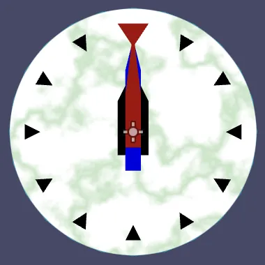
Because the pattern is abstract we could mirror it without it looking weird. We can do this by replacing the UV coordinates used for sampling the texture with 1 minus the coordinates. If we do this for both dimensions we mirror the pattern both horizontally and vertically.
COLOR.rgb = texture(TEXTURE, vec2(1.0) - UV).rgb;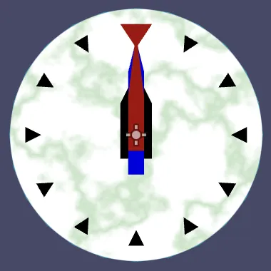
When performing calculations with vectors it's also allowed to use single values to represent a vector that has that value for all its components, so we don't have to explicitly construct vectors all the time.
COLOR.rgb = texture(TEXTURE, 1.0 - UV).rgb;Random Mirroring
We're currently mirroring the pattern for all clocks, which doesn't add any variety. To consistently only mirror the pattern for some clocks and not others we have to make this choice once and send it to the GPU per clock. Fortunately we still have the alpha channel of the modulation color available. So let's store a random value in the 0–1 range in it. To keep it constant per clock we have to do this in _ready().
func _ready() -> void:
	…
	visualization.self_modulate.a = randf()
GDScript doesn't support swizzling so we have to copy over the alpha value in _process() when setting a new color.
func _process(delta: float) -> void:
	…
	visualization.self_modulate = Color(s, m, h, visualization.self_modulate.a)
Now we have to upgrade clock_data to a full vec4 variable.
varying flat vec4 clock_data;

…

void vertex() {
	clock_data = COLOR;
}
Let's decide to use the original UV coordinates to sample the texture if the picked value is greater than 0.5, otherwise we reverse them.
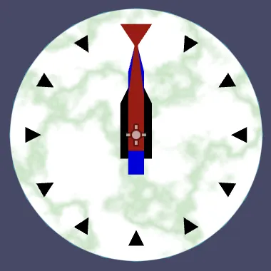
COLOR.rgb = texture(TEXTURE, clock_data.w > 0.5 ? UV : 1.0 - UV).rgb;Now our clock has either the normal or mirrored pattern, at random. We can go a step further and make this decision separately for both dimensions. We apply the current choice to only the U coordinate and shift the choice for V by 0.25. We use the original V only if the chosen value less is than 0.25 or greater than 0.75. The logical OR operator is ||.
	float choice = clock_data.w;
	COLOR.rgb = texture(
			TEXTURE,
			vec2(
					choice > 0.5 ? UV.x : 1.0 - UV.x,
					choice < 0.25 || choice > 0.75 ? UV.y : 1.0 - UV.y
			)
	).rgb;
This produces four variations based on the chosen value, with equal probability.
Are more variations possible?
Yes, it is also possible to rotate the UV coordinates. If the pattern was made to tile we could also add a random offset. There are many more ways in which patterns can be varied, but they require more work.
We've finished adding features to our clock. Below is the entire shader that we created.
shader_type canvas_item;

uniform vec3 second_color : source_color = vec3(0.5, 0.0, 0.0);
uniform vec3 minute_color : source_color = vec3(0.0, 0.5, 0.0);
uniform vec3 hour_color : source_color = vec3(0.0, 0.0, 0.5);

const float RING_THICKNESS = 0.1;
const float SMOOTHING = 1.5;

varying flat vec4 clock_data;

float smooth_above(float threshold, float value) {
	return smoothstep(threshold, threshold + fwidth(SMOOTHING * value), value);
}

float smooth_below(float threshold, float value) {
	return smoothstep(threshold, threshold - fwidth(SMOOTHING * value), value);
}

float get_ring_weight(float start_radius, float radius) {
	return (
			smooth_above(start_radius, radius) *
			smooth_below(start_radius + RING_THICKNESS, radius)
	);
}

vec3 add_ring(vec3 color, vec3 ring_color, float start_radius, float radius) {
	return mix(color, ring_color, get_ring_weight(start_radius, radius));
}

void vertex() {
	clock_data = COLOR;
}

void fragment() {
	// Clock radius at fragment, normalized so it is 1.0 at its face edge.
	float radius = 2.0 * distance(UV, vec2(0.5));
	float choice = clock_data.w;
	COLOR.rgb = texture(
			TEXTURE,
			vec2(
					choice > 0.5 ? UV.x : 1.0 - UV.x,
					choice < 0.25 || choice > 0.75 ? UV.y : 1.0 - UV.y
			)
	).rgb;
	COLOR.rgb = add_ring(COLOR.rgb, second_color, clock_data.x, radius);
	COLOR.rgb = add_ring(COLOR.rgb, minute_color, clock_data.y, radius);
	COLOR.rgb = add_ring(COLOR.rgb, hour_color, clock_data.z, radius);
	COLOR.a = smooth_below(1.0, radius);
}
The next tutorial is Migrating to C#.