Flat and Wireframe Shading
Derivatives and Geometry
- Use screen-space derivatives to find triangle normals.
- Do the same via a geometry shader.
- Use generated barycentric coordinates to create a wireframe.
- Make the wires fixed-width and configurable.
This tutorial covers how to add support for flat shading and showing the wireframe of a mesh. It uses advanced rendering techniques and assumes you're familiar with the material covered in the Rendering series.
This tutorial is made with Unity 2017.1.0.

Flat Shading
Meshes consist of triangles, which are flat by definition. We use surface normal vectors to add the illusion of curvature. This makes it possible to create meshes that represent seemingly smooth surfaces. However, sometimes you actually want to display flat triangles, either for style or to better see the mesh's topology.
To make the triangles appear as flat as they really are, we have to use the surface normals of the actual triangles. It will give meshes a faceted appearance, known as flat shading. This can be done by making the normal vectors of a triangle's three vertices equal to the triangle's normal vector. This makes it impossible to share vertices between triangles, because then they would share normals as well. So we end up with more mesh data. It would be convenient if we could keep sharing vertices. Also, it would be nice if we could use a flat-shading material with any mesh, overriding its original normals, if any.
Besides flat shading, it can also be useful or stylish to show a mesh's wireframe. This makes the topology of the mesh even more obvious. Ideally, we can do both flat shading and wireframe rendering with a custom material, in a single pass, for any mesh. To create such a material, we need a new shader. We'll use the final shader from part 20 of the Rendering series as our base. Duplicate My First Lighting Shader and change its name to Flat Wireframe.
Rendering 20 unitypackageShader "Custom/Flat Wireframe" { … }
Derivative Instructions
Because triangles are flat, their surface normal is the same at every point on their surface. Hence, each fragment rendered for a triangle should use the same normal vector. But we current do not know what this vector is. In the vertex program, we only have access to the vertex data stored in the mesh, processed in isolation. The normal vector stored here is of no use to us, unless it's designed to represent the triangle's normal. And in the fragment program, we only have access to the interpolated vertex normals.
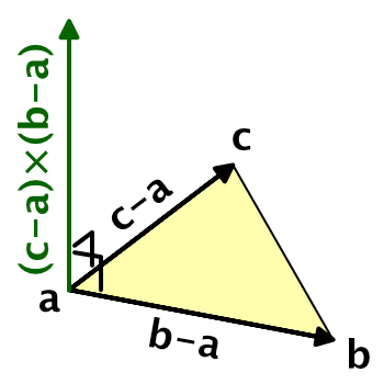
To determine the surface normal, we need to know the orientation of the triangle in world space. This can be determined via the positions of the triangle's vertices. Assuming that the triangle is not degenerate, its normal vector is equal to the normalized cross product of two of the triangle's edges. If it is degenerate, then it won't be rendered anyway. So gives a triangle's vertices `a`, `b`, and `c` in counter-clockwise order, its normal vector is `n=(c-a)xx(b-a)`. Normalizing that gives us the final unit normal vector, `hatn=n/|n|`.
We don't actually need to use the triangle's vertices. Any three points that lie in the triangle's plane will do, as long as those points form a triangle too. Specifically, we only need two vectors that lie in the triangle's plane, as long as they're not parallel and are larger than zero.
One possibility is to use points corresponding to the world positions of rendered fragments. For example, the world position of the fragment we're currently rendering, the position of the fragment to the right of it, and the position of the fragment above it, in screen space.
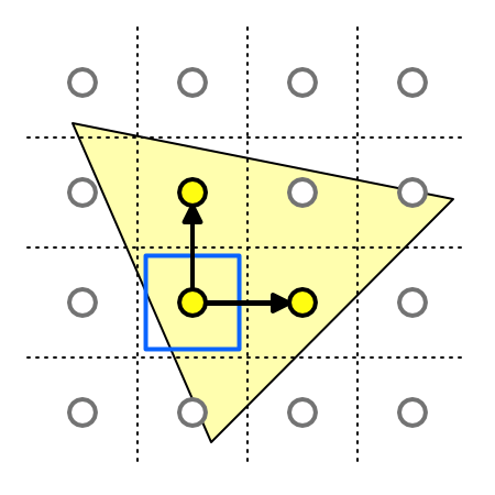
If we could access the world positions of adjacent fragments, then this could work. There is no way to directly access the data of adjacent fragments, but we can access the screen-space derivatives of this data. This is done via special instructions, which tell us the rate of change between fragments, for any piece of data, in either the screen-space X or Y dimension.
For example, our current fragment's world position is `p_0`. The position of the next fragment in the screen-space X dimension is `p_x`. The rate of change of the world position in the X dimension between these two fragments is thus `(delp)/(delx)=p_x-p_0`. This is the partial derivative of the world position, in the screen-space X dimension. We can retrieve this data in the fragment program via the ddx function, by supplying it with the world position. Let's do this at the start of the InitializeFragmentNormal function in My Lighting.cginc.
void InitializeFragmentNormal(inout Interpolators i) {
	float3 dpdx = ddx(i.worldPos);

	…
}
We can do the same for the screen-space Y dimension, finding `(delp)/(dely)=p_y-p_0` by invoking the ddy function with the world position.
	float3 dpdx = ddx(i.worldPos);
	float3 dpdy = ddy(i.worldPos);
Because these values represent the differences between the fragment world positions, they define two edges of a triangle. We don't actually know the exact shape of that triangle, but it's guaranteed to lie in the original triangle's plane, and that's all that matters. So the final normal vector is the normalized cross product of those vectors. Override the original normal with this vector.
	float3 dpdx = ddx(i.worldPos);
	float3 dpdy = ddy(i.worldPos);
	i.normal = normalize(cross(dpdy, dpdx));
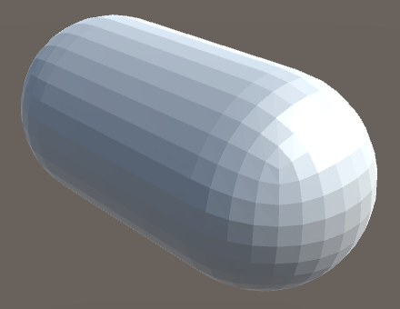
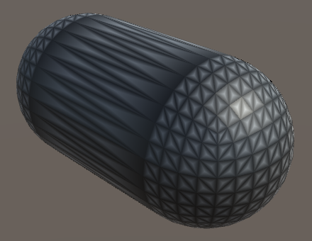
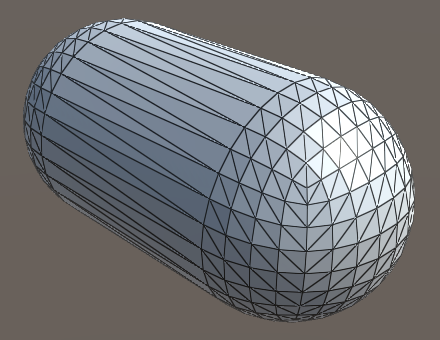
Create a new material that uses our Flat Wireframe shader. Any mesh that uses this material should be rendered using flat shading. They will appear faceted, though this might be hard to see when you're also using normal maps. I use a standard capsule mesh in the screenshots for this tutorial, with a gray material.
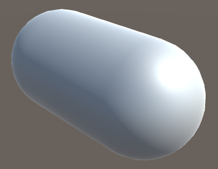
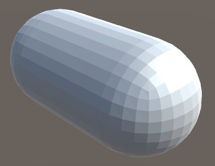
From a distance, it might look like the capsule's made out of quads, but those quads are made of two triangles each.

While this works, we've actually changed the behavior of all shaders that rely on the My Lighting include file. So remove the code that we just added.
// float3 dpdx = ddx(i.worldPos);// float3 dpdy = ddy(i.worldPos);// i.normal = normalize(cross(dpdy, dpdx));
Geometry Shaders
There is another way that we can determine the triangle's normal. Instead of using derivative instructions, we could use the actual triangle vertices to compute the normal vector. This requires use to do work per triangle, not per individual vertex or fragment. That's where geometry shaders come in.
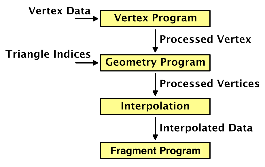
The geometry shader stage sits in between the vertex and the fragment stage. It is fed the output of the vertex program, grouped per primitive. A geometry program can modify this data, before it gets interpolated and used to render fragments.
The added value of the geometry shader is that the vertices are fed to it per primitive, so three for each triangle in our case. Whether mesh triangles share vertices doesn't matter, because the geometry program outputs new vertex data. This allows us to derive the triangle's normal vector and use it as the normal for all three vertices.
Let's put the code for our geometry shader in its own include file, MyFlatWireframe.cginc. Have this file include My Lighting.cginc and define a MyGeometryProgram function. Start with an empty void function.
#if !defined(FLAT_WIREFRAME_INCLUDED)
#define FLAT_WIREFRAME_INCLUDED

#include "My Lighting.cginc"

void MyGeometryProgram () {}

#endif
Geometry shaders are only supported when targeting shader model 4.0 or higher. Unity will automatically increase the target to this level if it was defined lower, but let's be explicit about it. To actually use a geometry shader, we have to add the #pragma geometry directive, just like for the vertex and fragment functions. Finally, MyFlatWireframe has to be included instead of My Lighting. Apply these changes to the base, additive, and deferred passes of our Flat Wireframe shader.
#pragma target 4.0 … #pragma vertex MyVertexProgram #pragma fragment MyFragmentProgram #pragma geometry MyGeometryProgram …// #include "My Lighting.cginc"#include "MyFlatWireframe.cginc"
This will result in shader compiler errors, because we haven't defined our geometry function correctly yet. We have to declare how many vertices it will output. This number can vary, so we must provide a maximum. Because we're working with triangles, we'll always output three vertices per invocation. This is specified by adding the maxvertexcount attribute to our function, with 3 as an argument.
[maxvertexcount(3)]
void GeometryProgram () {}
The next step is to define the input. As we're working with the output of the vertex program before interpolation, the data type is InterpolatorsVertex. So the type name isn't technically correct in this case, but we didn't took the geometry shader into consideration when we named it.
[maxvertexcount(3)]
void MyGeometryProgram (InterpolatorsVertex i) {}
We also have to declare which type of primitive we're working on, which is triangle in our case. This has to be specified before the input type. Also, as triangles have three vertices each, we're working on an array of three structures. We have to define this explicitly.
[maxvertexcount(3)]
void MyGeometryProgram (triangle InterpolatorsVertex i[3]) {}
Because the amount of vertices that a geometry shader can output varies, we don't have a singular return type. Instead, the geometry shader writes to a stream of primitives. In our case, it's a TriangleStream, which has to be specified as an inout parameter.
[maxvertexcount(3)]
void MyGeometryProgram (
	triangle InterpolatorsVertex i[3],
	inout TriangleStream stream
) {}
TriangleStream works like a generic type in C#. It needs to know the type of the vertex data that we're going to give it, which is still InterpolatorsVertex.
[maxvertexcount(3)]
void MyGeometryProgram (
	triangle InterpolatorsVertex i[3],
	inout TriangleStream<InterpolatorsVertex> stream
) {}
Now that the function signature is correct, we have to put the vertex data into the stream. This is done by invoking the stream's Append function once per vertex, in the order that we received them.
[maxvertexcount(3)]
void MyGeometryProgram (
	triangle InterpolatorsVertex i[3],
	inout TriangleStream<InterpolatorsVertex> stream
) {
	stream.Append(i[0]);
	stream.Append(i[1]);
	stream.Append(i[2]);
}
At this point our shader works again. We've added a custom geometry stage, which simply passes through the output from the vertex program, unmodified.
Modifying Vertex Normals Per Triangle
To find the triangle's normal vector, begin by extracting the world positions of its three vertices.
	float3 p0 = i[0].worldPos.xyz;
	float3 p1 = i[1].worldPos.xyz;
	float3 p2 = i[2].worldPos.xyz;

	stream.Append(i[0]);
	stream.Append(i[1]);
	stream.Append(i[2]);
Now we can perform the normalized cross product, once per triangle.
	float3 p0 = i[0].worldPos.xyz;
	float3 p1 = i[1].worldPos.xyz;
	float3 p2 = i[2].worldPos.xyz;

	float3 triangleNormal = normalize(cross(p1 - p0, p2 - p0));
Replace the vertex normals with this triangle normal.
	float3 triangleNormal = normalize(cross(p1 - p0, p2 - p0));
	i[0].normal = triangleNormal;
	i[1].normal = triangleNormal;
	i[2].normal = triangleNormal;
We end up with the same results as before, but now using a geometry shader stage instead of relying on screen-space derivative instructions.
Rendering the Wireframe
After taking care of the flat shading, we move on to rendering the mesh's wireframe. We're not going to create new geometry, nor will we use an extra pass to draw lines. We'll create the wireframe visuals by adding a line effect on the inside of triangles, along their edges. This can create a convincing wireframe, although the lines defining a shape's silhouette will appear half as thick as the lines on the inside. This usually isn't very noticeable, so we'll accept this inconsistency.
Barycentric Coordinates
To add line effects to the triangle edges, we need to know a fragment's distance to the nearest edge. This means that topological information about the triangle needs to be available in the fragment program. This can be done by adding the barycentric coordinates of the triangle to the interpolated data.
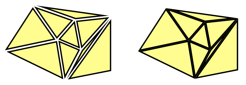
One way to add barycentric coordinates to triangles is to use the mesh's vertex colors to store them. The first vertex of each triangle becomes red, the second becomes green, and the third becomes blue. However, this would require meshes with vertex colors assigned this way, and makes it impossible to share vertices. We want a solution that works with any mesh. Fortunately, we can use our geometry program to add the required coordinates.
Because the barycentric coordinates are not provided by the mesh, the vertex program doesn't know about them. So they're not part of the InterpolatorsVertex structure. To have the geometry program output them, we have to define a new structure. Begin by defining InterpolatorsGeometry above MyGeometryProgram. It should contain the same data as InterpolatorsVertex, so use that as its contents.
struct InterpolatorsGeometry {
	InterpolatorsVertex data;
};
Adjust the stream data type of MyGeometryProgram so it uses the new structure. Define variables of this type inside the function, assign the input data to them, and append them to the stream, instead of directly passing the input through.
void MyGeometryProgram (
	triangle InterpolatorsVertex i[3],
	inout TriangleStream<InterpolatorsGeometry> stream
) {
	…

	InterpolatorsGeometry g0, g1, g2;
	g0.data = i[0];
	g1.data = i[1];
	g2.data = i[2];

	stream.Append(g0);
	stream.Append(g1);
	stream.Append(g2);
}
Now we can add additional data to InterpolatorsGeometry. Give it a float3 barycentricCoordinators vector, using the tenth interpolator semantic.
struct InterpolatorsGeometry {
	InterpolatorsVertex data;
	float3 barycentricCoordinates : TEXCOORD9;
};
Give each vertex a barycentric coordinate. It doesn't matter which vertex gets what coordinate, as long as they are valid.
	g0.barycentricCoordinates = float3(1, 0, 0);
	g1.barycentricCoordinates = float3(0, 1, 0);
	g2.barycentricCoordinates = float3(0, 0, 1);

	stream.Append(g0);
	stream.Append(g1);
	stream.Append(g2);
Note that the barycentric coordinates always add up to 1. So we could suffice with only passing on two, deriving the third coordinate by subtracting the other two from 1. That means we have to interpolate one less number, so let's make that change.
struct InterpolatorsGeometry {
	InterpolatorsVertex data;
	float2 barycentricCoordinates : TEXCOORD9;
};

	[maxvertexcount(3)]
void MyGeometryProgram (
	triangle InterpolatorsVertex i[3],
	inout TriangleStream<InterpolatorsGeometry> stream
) {
	…

	g0.barycentricCoordinates = float2(1, 0);
	g1.barycentricCoordinates = float2(0, 1);
	g2.barycentricCoordinates = float2(0, 0);

	…
}
Defining Extra Interpolators
At this point we're passing the barycentric coordinates to the fragment program, but it doesn't know about them yet. We have to add them to the definition of Interpolators in My Lighting. But we can't simply assume that this data is available. That's only the case for our Flat Wireframe shader. So let's make it possible for anyone using My Lighting to define their own interpolator data made available via a geometry shader, by defining it via a CUSTOM_GEOMETRY_INTERPOLATORS macro. To support this, insert the macro into Interpolators if it has been defined at that point.
struct Interpolators {
	…

	#if defined (CUSTOM_GEOMETRY_INTERPOLATORS)
		CUSTOM_GEOMETRY_INTERPOLATORS
	#endif
};
Now we can define this macro in MyFlatWireframe. We have to do this before including My Lighting. We can also use it in InterpolatorsGeometry, so we only have to write the code once.
#define CUSTOM_GEOMETRY_INTERPOLATORS \
	float2 barycentricCoordinates : TEXCOORD9;

#include "My Lighting.cginc"

struct InterpolatorsGeometry {
	InterpolatorsVertex data;
//	float2 barycentricCoordinates : TEXCOORD9;
	CUSTOM_GEOMETRY_INTERPOLATORS
};
Splitting My Lighting
How are we going to use the barycentric coordinates to visualize the wireframe? However we do it, My Lighting should not be involved. Instead, we can make it possible to rewire its functionality via another file, by inserting our own function in its code.
To overwrite functionality of My Lighting, we have to define the new code before including the file. But to do so we need access to the interpolators, which are defined in My Lighting, so we have to include it first. To solve this problem, we have to split My Lighting in two files. Copy the code at the start of My Lighting, taking the include statements, interpolator structures, and all Get functions. Put this code in a new My Lighting Input.cginc file. Give the file its own include guard define, MY_LIGHTING_INPUT_INCLUDED.
#if !defined(MY_LIGHTING_INPUT_INCLUDED)
#define MY_LIGHTING_INPUT_INCLUDED

#include "UnityPBSLighting.cginc"
#include "AutoLight.cginc"

#if defined(FOG_LINEAR) || defined(FOG_EXP) || defined(FOG_EXP2)
	#if !defined(FOG_DISTANCE)
		#define FOG_DEPTH 1
	#endif
	#define FOG_ON 1
#endif

…

float3 GetEmission (Interpolators i) {
	#if defined(FORWARD_BASE_PASS) || defined(DEFERRED_PASS)
		#if defined(_EMISSION_MAP)
			return tex2D(_EmissionMap, i.uv.xy) * _Emission;
		#else
			return _Emission;
		#endif
	#else
		return 0;
	#endif
}

#endif
Delete the same code from My Lighting. To keep existing shaders working, include My Lighting Input instead.
#if !defined(MY_LIGHTING_INCLUDED) #define MY_LIGHTING_INCLUDED//#include "UnityPBSLighting.cginc"// …////float3 GetEmission (Interpolators i) {// …//}#include "My Lighting Input.cginc" void ComputeVertexLightColor (inout InterpolatorsVertex i) { #if defined(VERTEXLIGHT_ON) i.vertexLightColor = Shade4PointLights( unity_4LightPosX0, unity_4LightPosY0, unity_4LightPosZ0, unity_LightColor[0].rgb, unity_LightColor[1].rgb, unity_LightColor[2].rgb, unity_LightColor[3].rgb, unity_4LightAtten0, i.worldPos.xyz, i.normal ); #endif }
Now it is possible to include My Lighting Input before including My Lighting. Its include guard will make sure that duplicate inclusion will be prevented. Do so in MyFlatWireframe.
#include "My Lighting Input.cginc"

#include "My Lighting.cginc"
Rewiring Albedo
Let's add the wireframe effect by adjusting the material's albedo. This requires us to replace the default albedo function of My Lighting. Like for custom geometry interpolators, we'll do this via a macro, ALBEDO_FUNCTION. In My Lighting, after we're sure that the input has been included, check whether this macro has been defined. If not, define it as the GetAlbedo function, making that the default.
#include "My Lighting Input.cginc"

#if !defined(ALBEDO_FUNCTION)
	#define ALBEDO_FUNCTION GetAlbedo
#endif
In the MyFragmentProgram function, replace the invocation of GetAlbedo with the macro.
	float3 albedo = DiffuseAndSpecularFromMetallic(
		ALBEDO_FUNCTION(i), GetMetallic(i), specularTint, oneMinusReflectivity
	);
Now we can create our own albedo function in MyFlatWireframe, after including My Lighting Input. It needs to have the same form as the original GetAlbedo function. Begin by simply passing through the result of the original function. After that, define the ALBEDO_FUNCTION macro with our own function's name, then include My Lighting.
#include "My Lighting Input.cginc"

float3 GetAlbedoWithWireframe (Interpolators i) {
	float3 albedo = GetAlbedo(i);
	return albedo;
}

#define ALBEDO_FUNCTION GetAlbedoWithWireframe

#include "My Lighting.cginc"
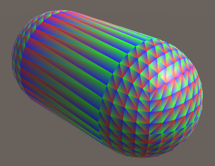
To verify that we have indeed control over the fragment's albedo, use the barycentric coordinates directly as the albedo.
float3 GetAlbedoWithWireframe (Interpolators i) {
	float3 albedo = GetAlbedo(i);
	float3 barys;
	barys.xy = i.barycentricCoordinates;
	barys.z = 1 - barys.x - barys.y;
	albedo = barys;
	return albedo;
}
Creating Wires
To create the wireframe effect, we need to know how close the fragment is to the nearest triangle edge. We can find this by taking the minimum of the barycentric coordinates. This gives us the minimum distance to the edge, in the barycentric domain. Let's use that directly as the albedo.
float3 albedo = GetAlbedo(i); float3 barys; barys.xy = i.barycentricCoordinates; barys.z = 1 - barys.x - barys.y;// albedo = barys;float minBary = min(barys.x, min(barys.y, barys.z)); return albedo * minBary;
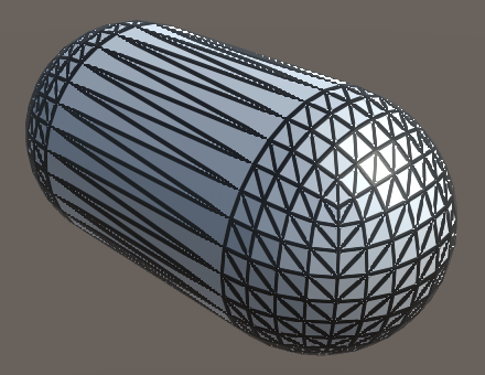
This looks somewhat like a black wireframe on top of a white mesh, but it is too fuzzy. That's because the distance to the nearest edge goes from zero at the edges to ⅓ at the center of the triangle. To make it look more like thin lines we have to fade to white quicker, for example by transitioning from black to white between 0 and 0.1. To make the transition smooth, let's use the smoothstep function for this.
	float minBary = min(barys.x, min(barys.y, barys.z));
	minBary = smoothstep(0, 0.1, minBary);
	return albedo * minBary;
Fixed Wire Width
The wireframe effect is starting to look good, but only for triangles with edges that have roughly the same length. Also, the lines are affected by view distance, because they're part of the triangles. Ideally, the wires have a fixed visual thickness.
To keep the wire thickness constant in screen space, we have to adjust the range that we use for the smoothstep function. The range depends on how quickly the measured distance to the edge changes, visually. We can use screen-space derivative instructions to figure this out.
The rate of change can be different for both screen-space dimensions. Which should we use? We can use both, simply adding them. Also, because the changes could be positive or negative, we should use their absolute values. By using the result directly as the range, we end up with lines that cover roughly two fragments.
	float minBary = min(barys.x, min(barys.y, barys.z));
	float delta = abs(ddx(minBary)) + abs(ddy(minBary));
	minBary = smoothstep(0, delta, minBary);
This formula is also available as the convenient fwidth function, so let's use that.
float delta = fwidth(minBary);
The resulting wires might appear a bit too thin. We can fix that by shifting the transition a little away from the edge, for example by the same value we use for the blend range.
minBary = smoothstep(delta, 2 * delta, minBary);
This produces clearer lines, but also reveals aliasing artifacts in the lines near triangle corners. The artifacts appear because the nearest edge suddenly changes in those regions, which leads to discontinuous derivatives. To fix this, we have to use the derivatives of the individual barycentric coordinates, blend them separately, and grab the minimum after that.
barys.z = 1 - barys.x - barys.y; float3 deltas = fwidth(barys); barys = smoothstep(deltas, 2 * deltas, barys); float minBary = min(barys.x, min(barys.y, barys.z));// float delta = fwidth(minBary);// minBary = smoothstep(delta, 2 * delta, minBary);return albedo * minBary;
Configurable Wires
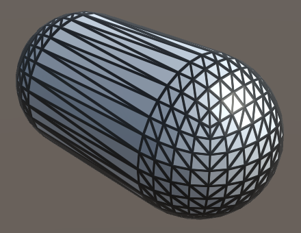
We have a functional wireframe effect, but you might want to use a different line thickness, blend region, or color. Maybe you'd like to use different settings per material. So let's make it configurable. To do so, add three properties to the Flat Wireframe shader. First is the wireframe color, with black as default. Second is the wireframe smoothing, which controls the transition range. A range from zero to ten should be sufficient, with a default of one, representing multiples of the fwidth measurement. Third is the wireframe thickness, with the same settings as smoothing.
		_WireframeColor ("Wireframe Color", Color) = (0, 0, 0)
		_WireframeSmoothing ("Wireframe Smoothing", Range(0, 10)) = 1
		_WireframeThickness ("Wireframe Thickness", Range(0, 10)) = 1
Add the corresponding variables to MyFlatWireframe and use them in GetAlbedoWithWireframe. Determine the final albedo by interpolating between the wireframe color and the original albedo, based on the smoothed minimum value.
float3 _WireframeColor;
float _WireframeSmoothing;
float _WireframeThickness;

float3 GetAlbedoWithWireframe (Interpolators i) {
	float3 albedo = GetAlbedo(i);
	float3 barys;
	barys.xy = i.barycentricCoordinates;
	barys.z = 1 - barys.x - barys.y;
	float3 deltas = fwidth(barys);
	float3 smoothing = deltas * _WireframeSmoothing;
	float3 thickness = deltas * _WireframeThickness;
	barys = smoothstep(thickness, thickness + smoothing, barys);
	float minBary = min(barys.x, min(barys.y, barys.z));
//	return albedo * minBary;
	return lerp(_WireframeColor, albedo, minBary);
}
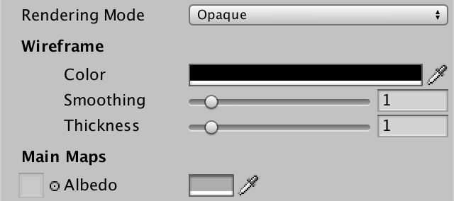
While the shader is now configurable, the properties don't appear in our custom shader GUI yet. We could create a new GUI for Flat Wireframe, but let's use a shortcut and add the properties directly to MyLightingShaderGUI. Give it a new DoWireframe method to create a small section for the wireframe.
	void DoWireframe () {
		GUILayout.Label("Wireframe", EditorStyles.boldLabel);
		EditorGUI.indentLevel += 2;
		editor.ShaderProperty(
			FindProperty("_WireframeColor"),
			MakeLabel("Color")
		);
		editor.ShaderProperty(
			FindProperty("_WireframeSmoothing"),
			MakeLabel("Smoothing", "In screen space.")
		);
		editor.ShaderProperty(
			FindProperty("_WireframeThickness"),
			MakeLabel("Thickness", "In screen space.")
		);
		EditorGUI.indentLevel -= 2;
	}
To have MyLightingShaderGUI support both shaders with and without a wireframe, only invoke DoWireframe in its OnGUI method if the shader has the _WireframeColor property. We simply assume that if that property is available, it has all three.
	public override void OnGUI (
		MaterialEditor editor, MaterialProperty[] properties
	) {
		this.target = editor.target as Material;
		this.editor = editor;
		this.properties = properties;
		DoRenderingMode();
		if (target.HasProperty("_WireframeColor")) {
			DoWireframe();
		}
		DoMain();
		DoSecondary();
		DoAdvanced();
	}
You're now able to render meshes with flat shading and a configurable wireframe. It will come in handy for the next advanced rendering tutorial, Tessellation.