Draw Calls
Shaders and Batches
- White a HLSL shader.
- Support the SRP batcher, GPU instancing, and dynamic batching.
- Configure material properties per object and draw many at random.
- Create transparent and cutout materials.
This is the second part of a tutorial series about creating a custom scriptable render pipeline. It covers the writing of shaders and drawing multiple objects efficiently.
This tutorial is made with Unity 2019.2.9f1 and upgraded to 2022.3.5f1.
Shaders
To draw something the CPU has to tell the GPU what to draw and how. What is drawn is usually a mesh. How it is drawn is defined by a shader, which is a set of instructions for the GPU. Besides the mesh, the shader needs additional information to do its work, including the object's transformation matrices and material properties.
Unity's LW/Universal and HD RPs allow you to design shaders with the Shader Graph package, which generates shader code for you. But our custom RP doesn't support that, so we have to write the shader code ourselves. This gives us full control over and understanding of what a shader does.
Unlit Shader
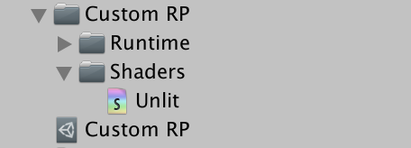
Our first shader will simply draw a mesh with a solid color, without any lighting. A shader asset can be created via one of the options in the Assets / Create / Shader menu. The Unlit Shader is most appropriate, but we're going to start fresh, by deleting all the default code from the created shader file. Name the asset Unlit and put in in a new Shaders folder under Custom RP.
Shader code looks like C# code for the most part, but it consists of a mix of different approaches, including some archaic old bits that made sense in the past but no more.
The shader is defined like a class, but with just the Shader keyword followed by a string that is used to create an entry for it in the Shader dropdown menu of materials. Let's use Custom RP/Unlit. It's followed by a code block, which contains more blocks with keywords in front of them. There's a Properties block to define material properties, followed by a SubShader block that needs to have a Pass block inside it, which defines one way to render something. Create that structure with otherwise empty blocks.
Shader "Custom RP/Unlit" {

	Properties {}

	SubShader {

		Pass {}
	}
}
That defines a minimal shader that compiles and allows us to create a material that uses it.
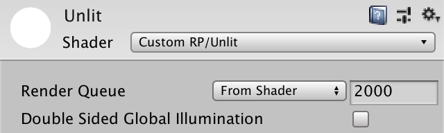
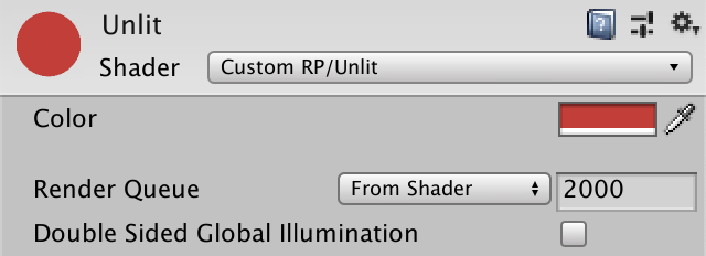
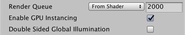
The default shader implementation renders the mesh solid white. The material shows a default property for the render queue, which it takes from the shader automatically and is set to 2000, which is the default for opaque geometry. It also has a toggle to enable double-sided global illumination, but that's not relevant for us.
HLSL Programs
The language that we use to write shader code is the High-Level Shading Language, HLSL for short. We have to put it in the Pass block, in between HLSLPROGRAM and ENDHLSL keywords. We have to do that because it's possible put other non-HLSL code inside the Pass block as well.
		Pass {
			HLSLPROGRAM
			ENDHLSL
		}
To draw a mesh the GPU has to rasterize all its triangles, converting it to pixel data. It does this by transforming the vertex coordinates from 3D space to 2D visualization space and then filling all pixels that are covered by the resulting triangle. These two steps are controlled by separate shader programs, both of which we have to define. The first is known as the vertex kernel/program/shader and the second as the fragment kernel/program/shader. A fragment corresponds to a display pixel or texture texel, although it might not represent the final result as it could be overwritten when something gets drawn on top of it later.
We have to identify both programs with a name, which is done via pragma directives. These are single-line statements beginning with #pragma and are followed by either vertex or fragment plus the relevant name. We'll use UnlitPassVertex and UnlitPassFragment.
			HLSLPROGRAM
			#pragma vertex UnlitPassVertex
			#pragma fragment UnlitPassFragment
			ENDHLSL
The shader compiler will now complain that it cannot find the declared shader kernels. We have to write HLSL functions with the same names to define their implementation. We could do this directly below the pragma directives, but we'll put all HLSL code in a separate file instead. Specifically, we'll use an UnlitPass.hlsl file in the same asset folder. We can instruct the shader compiler to insert the contents of that file by adding an #include directive with the relative path to the file.
			HLSLPROGRAM
			#pragma vertex UnlitPassVertex
			#pragma fragment UnlitPassFragment
			#include "UnlitPass.hlsl"
			ENDHLSL
Unity doesn't have a convenient menu option to create an HLSL file, so you'll have to do something like duplicate the shader file, rename it to UnlitPass, change its file extension to hlsl externally and clear its contents.

Include Guard
HLSL files are used to group code just like C# classes, although HLSL doesn't have the concept of a class. There is only a single global scope, besides the local scopes of code blocks. So everything is accessible everywhere. Including a files is also not the same as using a namespace. It inserts the entire contents of the file at the point of the include directive, so if you include the same file more than once you'll get duplicate code, which will most likely lead to compiler errors. To prevent that we'll add an include guard to UnlitPass.hlsl.
It is possible to use the #define directive to define any identifier, which is usually done in uppercase. We'll use this to define CUSTOM_UNLIT_PASS_INCLUDED at the top of the file.
#define CUSTOM_UNLIT_PASS_INCLUDED
This is an example of a simple macro that just defines an identifier. If it exists then it means that our file has been included. So we don't want to include its contents again. Phrased differently, we only want to insert the code when it hasn't been defined yet. We can check that with the #ifndef directive. Do this before defining the macro.
#ifndef CUSTOM_UNLIT_PASS_INCLUDED
#define CUSTOM_UNLIT_PASS_INCLUDED
All code following the #ifndef will be skipped and thus won't get compiled if the macro has already been defined. We have to terminate its scope by adding an #endif directive at the end of the file.
#ifndef CUSTOM_UNLIT_PASS_INCLUDED
#define CUSTOM_UNLIT_PASS_INCLUDED
#endif
Now we can be sure that all relevant code of the file will never be inserted multiple times, even if we end up including it more than once.
Shader Functions
We define our shader functions inside the scope of the include guard. They're written just like C# methods without any access modifiers. Begin with simple void functions that do nothing.
#ifndef CUSTOM_UNLIT_PASS_INCLUDED
#define CUSTOM_UNLIT_PASS_INCLUDED

void UnlitPassVertex () {}

void UnlitPassFragment () {}

#endif
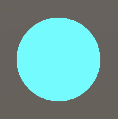
This is enough to get our shader to compile. The result might be a default cyan shader, if anything shows up at all.
To produce valid output we have to make our fragment function return a color. The color is defined with a four-component float4 vector containing its red, green, blue, and alpha components. We can define solid black via float4(0.0, 0.0, 0.0, 0.0) but we can also write a single zero, as single values get automatically expanded to a full vector. The alpha value doesn't matter because we're creating an opaque shader, so zero is fine.
float4 UnlitPassFragment () {
	return 0.0;
}
At this point the shader compiler will fail because our function is missing semantics. We have to indicate what we mean with the value that we return, because we could potentially produce lots of data with different meanings. In this case we provide the default system value for the render target, indicated by writing a colon followed by SV_TARGET after the parameter list of UnlitPassFragment.
float4 UnlitPassFragment () : SV_TARGET {
	return 0.0;
}
UnlitPassVertex is responsible for transforming vertex positions, so should return a position. That's also a float4 vector because it must be defined as a homogeneous clip space position, but we'll get to that later. Again we begin with the zero vector and in this case we have to indicate that its meaning is SV_POSITION.
float4 UnlitPassVertex () : SV_POSITION {
	return 0.0;
}
Space Transformation
When all vertices are set to zero the mesh collapses to a point and nothing gets rendered. The main job of the vertex function is to convert the original vertex position to the correct space. When invoked, the function is provided with the available vertex data, if we ask for it. We do that by adding parameters to UnlitPassVertex. We need the vertex position, which is defined in object space, so we'll name it positionOS, using the same convention as Unity's new RPs. The position's type is float3, because it's a 3D point. Let's initially return it, adding 1 as the fourth required component via float4(positionOS, 1.0).
float4 UnlitPassVertex (float3 positionOS) : SV_POSITION {
	return float4(positionOS, 1.0);
}
We also have to add semantics to input, because vertex data can contain more than just a position. We need POSITION in this case, added with a colon directly after the parameter name.
float4 UnlitPassVertex (float3 positionOS : POSITION) : SV_POSITION {
	return float4(positionOS, 1.0);
}
The mesh shows up again, but incorrect because the position that we output is in the wrong space. Space conversion requires matrices, which are send to the GPU when something gets drawn. We have to add these matrices to our shader, but because they're always the same we'll put the standard input provided by Unity in a separate HLSL file, both to keep code structured and to be able to include the code in other shaders. Add a UnityInput.hlsl file and put it in a ShaderLibrary folder directly under Custom RP, to mirror the folder structure of Unity's RPs.

Begin the file with a CUSTOM_UNITY_INPUT_INCLUDED include guard and then define a float4x4 matrix named unity_ObjectToWorld in the global scope. In a C# class this would define a field, but here it's known as a uniform value. It's set by the GPU once per draw, remaining constant—uniform—for all invocations of the vertex and fragment functions during that draw.
#ifndef CUSTOM_UNITY_INPUT_INCLUDED
#define CUSTOM_UNITY_INPUT_INCLUDED

float4x4 unity_ObjectToWorld;

#endif
We can use the matrix to convert from object space to world space. As this is common functionality let's create a function for it and put it in yet another file, this time Common.hlsl in the same ShaderLibrary folder. We include UnityInput there and then declare a TransformObjectToWorld function with a float3 as both input and output.
#ifndef CUSTOM_COMMON_INCLUDED
#define CUSTOM_COMMON_INCLUDED

#include "UnityInput.hlsl"

float3 TransformObjectToWorld (float3 positionOS) {
	return 0.0;
}

#endif
The space conversion is done by invoking the mul function with a matrix and a vector. In this case we do need a 4D vector, but as its fourth component is always 1 we can add it ourselves by using float4(positionOS, 1.0). The result is again a 4D vector with always 1 as its fourth component. We can extract the first three components from it by accessing the xyz property of the vector, which is known as a swizzle operation.
float3 TransformObjectToWorld (float3 positionOS) {
	return mul(unity_ObjectToWorld, float4(positionOS, 1.0)).xyz;
}
We can now covert to world space in UnlitPassVertex. First include Common.hlsl directly above the function. As it exists in a different folder we can reach it via the relative path ../ShaderLibrary/Common.hlsl. Then use TransformObjectToWorld to calculate a positionWS variable and return it instead of the object-space position.
#include "../ShaderLibrary/Common.hlsl"

float4 UnlitPassVertex (float3 positionOS : POSITION) : SV_POSITION {
	float3 positionWS = TransformObjectToWorld(positionOS.xyz);
	return float4(positionWS, 1.0);
}
The result is still wrong because we need a position in homogeneous clip space. This space defines a cube containing everything that is in view of the camera, distorted into a trapezoid in case of a perspective camera. Transforming from world space to this space can be done by multiplying with the view-projection matrix, which accounts for the camera's position, orientation, projection, field-of-view, and near-far clipping planes. It's made available the unity_ObjectToWorld matrix, so add it to UnityInput.hlsl.
float4x4 unity_ObjectToWorld;

float4x4 unity_MatrixVP;
Add a TransformWorldToHClip to Common.hlsl which works the same as TransformObjectToWorld, except its input is in world space, uses the other matrix, and produces a float4.
float3 TransformObjectToWorld (float3 positionOS) {
	return mul(unity_ObjectToWorld, float4(positionOS, 1.0)).xyz;
}

float4 TransformWorldToHClip (float3 positionWS) {
	return mul(unity_MatrixVP, float4(positionWS, 1.0));
}
Have UnlitPassVertex use the function to return the position in the correct space.
float4 UnlitPassVertex (float3 positionOS : POSITION) : SV_POSITION {
	float3 positionWS = TransformObjectToWorld(positionOS.xyz);
	return TransformWorldToHClip(positionWS);
}
Core Library
The two functions that we just defined are so common that they're also included in the Core RP Pipeline package. The core library defines many more useful and essential things, so let's install that package, remove our own definitions and instead include the relevant file, in this case Packages/com.unity.render-pipelines.core/ShaderLibrary/SpaceTransforms.hlsl.
//float3 TransformObjectToWorld (float3 positionOS) {// return mul(unity_ObjectToWorld, float4(positionOS, 1.0)).xyz;//}//float4 TransformWorldToHClip (float3 positionWS) {// return mul(unity_MatrixVP, float4(positionWS, 1.0));//}#include "Packages/com.unity.render-pipelines.core/ShaderLibrary/SpaceTransforms.hlsl"
That fails to compile, because the code in SpaceTransforms.hlsl doesn't assume the existence of unity_ObjectToWorld. Instead it expects that the relevant matrix is defined as UNITY_MATRIX_M by a macro, so let's do that before including the file by writing #define UNITY_MATRIX_M unity_ObjectToWorld on a separate line. After that all occurrances of UNITY_MATRIX_M will get replaced by unity_ObjectToWorld. There's a reason for this that we'll discover later.
#define UNITY_MATRIX_M unity_ObjectToWorld

#include "Packages/com.unity.render-pipelines.core/ShaderLibrary/SpaceTransforms.hlsl"
This is also true for the inverse matrix, unity_WorldToObject, which should be defined via UNITY_MATRIX_I_M, the unity_MatrixV matrix via UNITY_MATRIX_V, and unity_MatrixVP via UNITY_MATRIX_VP. Finally, there also the projection matrix defined via UNITY_MATRIX_P which is made available as glstate_matrix_projection. We don't need these extra matrices but the code won't compile if we don't include them.
#define UNITY_MATRIX_M unity_ObjectToWorld
#define UNITY_MATRIX_I_M unity_WorldToObject
#define UNITY_MATRIX_V unity_MatrixV
#define UNITY_MATRIX_VP unity_MatrixVP
#define UNITY_MATRIX_P glstate_matrix_projection
Unity 2022 requires three additional matrices.
#define UNITY_MATRIX_M unity_ObjectToWorld
#define UNITY_MATRIX_I_M unity_WorldToObject
#define UNITY_MATRIX_V unity_MatrixV
#define UNITY_MATRIX_I_V unity_MatrixInvV
#define UNITY_MATRIX_VP unity_MatrixVP
#define UNITY_PREV_MATRIX_M unity_prev_MatrixM
#define UNITY_PREV_MATRIX_I_M unity_prev_MatrixIM
#define UNITY_MATRIX_P glstate_matrix_projection
Add the extra matrices to UnityInput as well.
float4x4 unity_ObjectToWorld;
float4x4 unity_WorldToObject;

float4x4 unity_MatrixVP;
float4x4 unity_MatrixV;
float4x4 unity_MatrixInvV;
float4x4 unity_prev_MatrixM;
float4x4 unity_prev_MatrixIM;
float4x4 glstate_matrix_projection;
The last thing missing is something else than a matrix. It's unity_WorldTransformParams, which contains some transform information that we again don't need here. It is a vector defined as real4, which isn't a valid type itself but instead an alias to either float4 or half4 depending on the target platform.
float4x4 unity_ObjectToWorld;
float4x4 unity_WorldToObject;
real4 unity_WorldTransformParams;
That alias and a lot of other basic macros are defined per graphics API and we can get all that by including Packages/com.unity.render-pipelines.core/ShaderLibrary/Common.hlsl. Do so in our Common.hlsl file before including UnityInput.hlsl. You can inspect those files in the imported package if you're curious about their contents.
#include "Packages/com.unity.render-pipelines.core/ShaderLibrary/Common.hlsl"
#include "UnityInput.hlsl"
Color
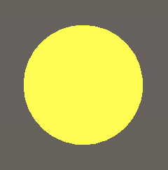
The color of the rendered object can be changed by adjusting UnlitPassFragment. For example, we can make it yellow by returning float4(1.0, 1.0, 0.0, 1.0) instead of zero.
float4 UnlitPassFragment () : SV_TARGET {
	return float4(1.0, 1.0, 0.0, 1.0);
}
To make it possible to configure the color per material we have to define it as a uniform value instead. Do this below the include directive, before the UnlitPassVertex function. We need a float4 and we'll name it _BaseColor. The leading underscore is the standard way to indicate that it represents a material property. Return this value instead of a hard-coded color in UnlitPassFragment.
#include "../ShaderLibrary/Common.hlsl"

float4 _BaseColor;

float4 UnlitPassVertex (float3 positionOS : POSITION) : SV_POSITION {
	float3 positionWS = TransformObjectToWorld(positionOS);
	return TransformWorldToHClip(positionWS);
}

float4 UnlitPassFragment () : SV_TARGET {
	return _BaseColor;
}
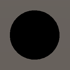
We're back to black because the default value is zero. To link it to the material we have to add _BaseColor to the Properties block in the Unlit shader file.
	Properties {
		_BaseColor
	}
The property name must be followed by a string for use in the inspector and a Color type identifier, as if providing arguments to a method.
_BaseColor("Color", Color)
Finally, we have to provide a default value, in this case by assigning a list of four numbers to it. Let's use white.
_BaseColor("Color", Color) = (1.0, 1.0, 1.0, 1.0)
Now it's possible to create multiple materials with our shader, each with a different color.
Batching
Every draw call requires communication between the CPU and GPU. If a lot of data has to be sent to the GPU then it might end up wasting time by waiting. And while the CPU is busy sending data it can't do other things. Both issues can lower the frame rate. At the moment our approach is straightforward: each object gets its own draw call. This is the worst way to do it, although we end up sending very little data so right now it's fine.
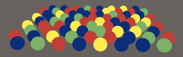
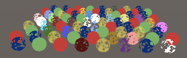
As an example, I made a scene with 76 spheres that each use one of four materials: red, green, yellow, and blue. It requires 78 draw calls to render, 76 for the spheres, one for the skybox, and one to clear the render target.
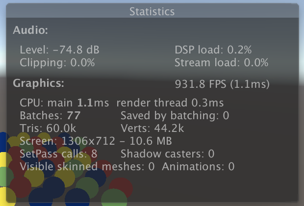
If you open the Stats panel of the Game window then you can see an overview of what it takes to render the frame. The interesting fact here is that it shows 77 batches—ignoring the clear—of which zero are saved by batching.
SRP Batcher
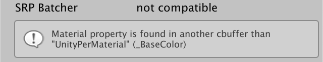
Batching is the process of combining draw calls, reducing the time spent communicating between CPU and GPU. The simplest way to do this is to enable the SRP batcher. However, this only works for compatible shaders, which our Unlit shader isn't. You can verify this by selecting it in the inspector. There is an SRP Batcher line that indicates incompatibility, under which it gives one reason for this.
Rather than reducing the amount of draw calls the SRP batches makes them leaner. It caches material properties on the GPU so they don't have to be sent every draw call. This reduces both the amount of data that has to be communicated and the work that the CPU has to do per draw call. But this only works if the shader adheres to a strict structure for uniform data.
All material properties have to be defined inside a concrete memory buffer instead of at the global level. This is done by wrapping the _BaseColor declaration in a cbuffer block with the UnityPerMaterial name. This works like a struct declaration, but has to be terminated with a semicolon. It segregates _BaseColor by putting it in a specific constant memory buffer, although it remains accessible at the global level.
cbuffer UnityPerMaterial {
	float _BaseColor;
};
Constant buffers aren't supported on all platforms—like OpenGL ES 2.0—so instead of using cbuffer directly we can use the CBUFFER_START and CBUFFER_END macros that we included from the Core RP Library. The first takes the buffer name as an argument, as if it were a function. In this case we end up with the exact same result as before, except that the cbuffer code will not exist for platforms that don't support it.
CBUFFER_START(UnityPerMaterial)
	float4 _BaseColor;
CBUFFER_END
We have to also do this for unity_ObjectToWorld, unity_WorldToObject, and unity_WorldTransformParams, except they have to be grouped in a UnityPerDraw buffer.
CBUFFER_START(UnityPerDraw)
	float4x4 unity_ObjectToWorld;
	float4x4 unity_WorldToObject;
	real4 unity_WorldTransformParams;
CBUFFER_END
In this case we're required to define specific groups of values if we use one of them. For the transformation group we also need to include float4 unity_LODFade, even though we don't use it. The exact order doesn't matter, but Unity puts it directly after unity_WorldToObject so let's do that as well.
CBUFFER_START(UnityPerDraw)
	float4x4 unity_ObjectToWorld;
	float4x4 unity_WorldToObject;
	float4 unity_LODFade;
	real4 unity_WorldTransformParams;
CBUFFER_END

With our shader compatible, the next step is to enable the SRP batcher, which is done by setting GraphicsSettings.useScriptableRenderPipelineBatching to true. We only have to do this once, so let's do it when our pipeline instance gets created, by adding a constructor method to CustomRenderPipeline.
	public CustomRenderPipeline () {
		GraphicsSettings.useScriptableRenderPipelineBatching = true;
	}
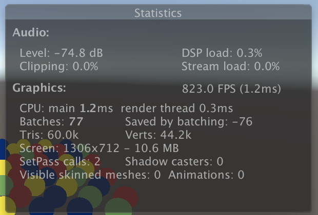
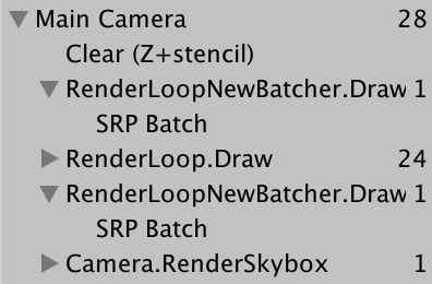
The Stats panel shows that 76 batches got saved, though it shows a negative number. The frame debugger now shows a single SRP Batch entry under RenderLoopNewBatcher.Draw, though keep in mind that it's not a single draw call but an optimized sequence of them.

Many Colors
We get one batch even though we use four materials. That works because all their data gets cached on the GPU and each draw call only has to contain an offset to the correct memory location. The only restriction is that the memory layout must be the same per material, which is the case because we use the same shader for all of them, only containing a single color property each. Unity doesn't compare the exact memory layout of materials, it simply only batches draw calls that use the exact same shader variant.
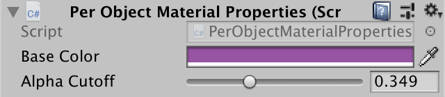
This work fine if we want a few different colors, but if we wanted to give each sphere its own color then we'd have to create many more materials. It would be more convenient if we could set the color per object instead. This isn't possible by default but we can support it by creating a custom component type. Name it PerObjectMaterialProperties. As it's an example I put it in an Examples folder under Custom RP.
The idea is that a game object could have one PerObjectMaterialProperties component attached to it, which has a Base Color configuration option, which will be used to set the _BaseColor material property for it. It needs to know the identifier of the shader property, which we can retrieve via Shader.PropertyToID and store in a static variable, like we do for the shader pass identifier in CameraRenderer, though in this case it's an integer.
using UnityEngine;

[DisallowMultipleComponent]
public class PerObjectMaterialProperties : MonoBehaviour {

	static int baseColorId = Shader.PropertyToID("_BaseColor");

	[SerializeField]
	Color baseColor = Color.white;
}
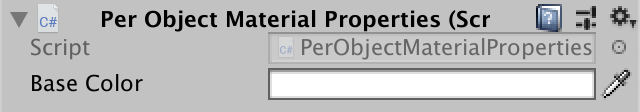
PerObjectMaterialProperties component.Setting per-object material properties is done via a MaterialPropertyBlock object. We only need one that all PerObjectMaterialProperties instances can reuse, so declare a static field for it.
static MaterialPropertyBlock block;
Create a new block if there isn't one already, then invoke SetColor on it with the property identifier and color, and then apply the block to the game object's Renderer component via SetPropertyBlock, which copies its settings. Do this in OnValidate so the results immediately show up in the editor.
	void OnValidate () {
		if (block == null) {
			block = new MaterialPropertyBlock();
		}
		block.SetColor(baseColorId, baseColor);
		GetComponent<Renderer>().SetPropertyBlock(block);
	}
I added the component to 24 arbitrary spheres and gave them different colors.
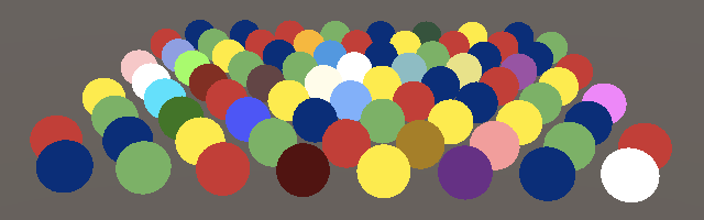
Unfortunately the SRP batcher cannot deal with per-object material properties. So the 24 spheres fall back to one regular draw call each, potentially splitting the other spheres in multiple batches as well, due to sorting.
Also, OnValidate doesn't get invoked in builds. To make the individual colors appear there we have to also apply them in Awake, which we can do by simply invoking OnValidate there.
	void Awake () {
		OnValidate();
	}
GPU Instancing
There is another way to consolidate draw calls that does work with per-object material properties. It's known as GPU instancing and works by issuing a single draw call for multiple objects with the same mesh at once. The CPU collects all per-object transformation and material properties and puts them in arrays which are send to the GPU. The GPU then iterates through all entries and renders them in the order that they are provided.
Because GPU instances requires data to be provided via arrays our shader currently doesn't support it. The first step to make this work is to add the #pragma multi_compile_instancing directive above the vertex and fragment pragmas in our shader's Pass block.
			#pragma multi_compile_instancing
			#pragma vertex UnlitPassVertex
			#pragma fragment UnlitPassFragment
That will make Unity generate two variants of our shader, one with and one without GPU instancing support. A toggle option has also appeared in the material inspector which allows us to choose which version to use per material.
Supporting GPU instancing requires a change of approach, for which we have to include the UnityInstancing.hlsl file from the core shader library. This has to be done after defining the UNITY_MATRIX_M and other macros and before including SpaceTransforms.hlsl.
#define UNITY_MATRIX_P glstate_matrix_projection

#include "Packages/com.unity.render-pipelines.core/ShaderLibrary/UnityInstancing.hlsl"
#include "Packages/com.unity.render-pipelines.core/ShaderLibrary/SpaceTransforms.hlsl"
What UnityInstancing.hlsl does is redefine those macros to access the instanced data arrays instead. But to make that work it needs to know the index of the object that's currently being rendered. The index is provided via the vertex data, so we have to make it available. UnityInstancing.hlsl defines macros to make this easy, but they assume that our vertex function has a struct parameter.
It is possible to declare a struct—just like a cbuffer—and use it as an input parameter for a function. We can also define semantics inside the struct. An advantage of this approach is that it's more legible than a long parameter list. So wrap the positionOS parameter of UnlitPassVertex in an Attributes struct, representing the vertex input data.
struct Attributes {
	float3 positionOS : POSITION;
};

float4 UnlitPassVertex (Attributes input) : SV_POSITION {
	float3 positionWS = TransformObjectToWorld(input.positionOS);
	return TransformWorldToHClip(positionWS);
}
When GPU instancing is used the object index is also available as a vertex attribute. We can add it when appropriate by simply putting UNITY_VERTEX_INPUT_INSTANCE_ID inside Attributes.
struct Attributes {
	float3 positionOS : POSITION;
	UNITY_VERTEX_INPUT_INSTANCE_ID
};
Next, add UNITY_SETUP_INSTANCE_ID(input); at the start of UnlitPassVertex. This extracts the index from the input and stores it in a global static variable that the other instancing macros rely on.
float4 UnlitPassVertex (Attributes input) : SV_POSITION {
	UNITY_SETUP_INSTANCE_ID(input);
	float3 positionWS = TransformObjectToWorld(input.positionOS);
	return TransformWorldToHClip(positionWS);
}
This is enough to get GPU instancing working, although the SRP batcher takes precedence so we don't get different results now. But we don't yet support per-instance material data. To add that we have to replace _BaseColor with an array reference when needed. This is done by replacing CBUFFER_START with UNITY_INSTANCING_BUFFER_START and CBUFFER_END with UNITY_INSTANCING_BUFFER_END, which now requires an argument as well. This needn't be the same as at the start, but there's no compelling reason to make them different.
//CBUFFER_START(UnityPerMaterial)// float4 _BaseColor;//CBUFFER_ENDUNITY_INSTANCING_BUFFER_START(UnityPerMaterial) float4 _BaseColor; UNITY_INSTANCING_BUFFER_END(UnityPerMaterial)
Then replace the definition of _BaseColor with UNITY_DEFINE_INSTANCED_PROP(float4, _BaseColor).
UNITY_INSTANCING_BUFFER_START(UnityPerMaterial)// float4 _BaseColor;UNITY_DEFINE_INSTANCED_PROP(float4, _BaseColor) UNITY_INSTANCING_BUFFER_END(UnityPerMaterial)
When instancing is in use we now have to also make the instance index available in UnlitPassFragment. To make this easy we'll use a struct to have UnlitPassVertex output both the position and index, using UNITY_TRANSFER_INSTANCE_ID(input, output); to copy the index when it exists. We name this struct Varyings like Unity does, as it contains the data can vary between fragments of the same triangle.
struct Varyings {
	float4 positionCS : SV_POSITION;
	UNITY_VERTEX_INPUT_INSTANCE_ID
};

Varyings UnlitPassVertex (Attributes input) { //: SV_POSITION {
	Varyings output;
	UNITY_SETUP_INSTANCE_ID(input);
	UNITY_TRANSFER_INSTANCE_ID(input, output);
	float3 positionWS = TransformObjectToWorld(input.positionOS);
	output.positionCS = TransformWorldToHClip(positionWS);
	return output;
}
Add this struct as a parameter to UnlitPassFragment. Then use UNITY_SETUP_INSTANCE_ID as before to make the index available. The material property must now be accessed via UNITY_ACCESS_INSTANCED_PROP(UnityPerMaterial, _BaseColor).
float4 UnlitPassFragment (Varyings input) : SV_TARGET {
	UNITY_SETUP_INSTANCE_ID(input);
	return UNITY_ACCESS_INSTANCED_PROP(UnityPerMaterial, _BaseColor);
}
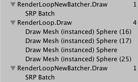
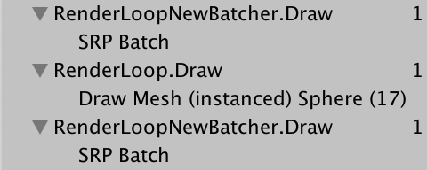
Unity is now able to combine the 24 spheres with per-object colors, reducing the amount of draw calls. I ended up with four instanced draw calls because those spheres still used four materials among them. GPU instancing only works for objects that share the same material. As they override the material color they can all use the same material, which then allows them to be drawn in a single batch.
Note that there a is limit to the batch size, based on the target platform and how much data has to be provided per instance. If you go over this limit then you end up with more than one batch. Also, sorting can still split batches if there are multiple materials in use.
Drawing Many Instanced Meshes
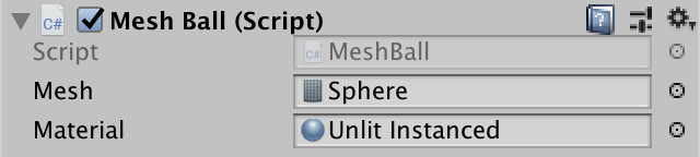
GPU instancing becomes a significant advantage when hundreds of objects can be combined in a single draw call. But editing so many objects in the scene by hand isn't practical. So let's generate a bunch at random. Create a MeshBall example component that will spawn a lot of objects when it awakens. Let it cache the _BaseColor shader property and add configuration options for a mesh and a material, which must support instancing.
using UnityEngine;

public class MeshBall : MonoBehaviour {

	static int baseColorId = Shader.PropertyToID("_BaseColor");

	[SerializeField]
	Mesh mesh = default;

	[SerializeField]
	Material material = default;
}
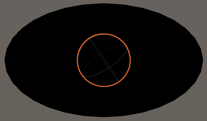
Create a game object with this component. I gave it the default sphere mesh to draw.
We could spawn many new game objects, but we don't have to. Instead we'll fill an array of transformation matrices and colors and tell the GPU to render a mesh with those. This is where GPU instancing is most useful. We can provide up to 1023 instances in one go, so let's add fields with arrays of that length, along with a MaterialPropertyBlock that we need to pass along the color data. The color array's element type has to be Vector4 in this case.
	Matrix4x4[] matrices = new Matrix4x4[1023];
	Vector4[] baseColors = new Vector4[1023];

	MaterialPropertyBlock block;
Create an Awake method that fills the arrays with random positions within a radius 10 sphere and random RGB color data.
	void Awake () {
		for (int i = 0; i < matrices.Length; i++) {
			matrices[i] = Matrix4x4.TRS(
				Random.insideUnitSphere * 10f, Quaternion.identity, Vector3.one
			);
			baseColors[i] =
				new Vector4(Random.value, Random.value, Random.value, 1f);
		}
	}
In Update we create a new block if it doesn't already exist and invoke SetVectorArray on it to configure the colors. After that invoke Graphics.DrawMeshInstanced with the mesh, sub-mesh index zero, material, matrices array, the amount of elements, and property block as arguments. We set up the block here so the mesh ball survives hot reloads.
	void Update () {
		if (block == null) {
			block = new MaterialPropertyBlock();
			block.SetVectorArray(baseColorId, baseColors);
		}
		Graphics.DrawMeshInstanced(mesh, 0, material, matrices, 1023, block);
	}
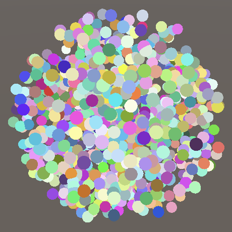
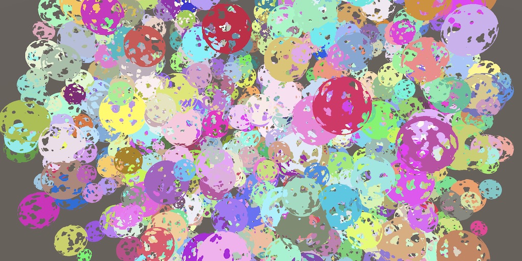
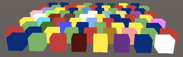
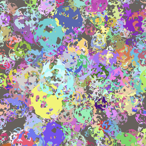
Entering play mode will now produce a dense ball of spheres. How many draw calls it takes depends on the platform, as the maximum buffer size per draw call differs. In my case it takes three draw calls to render.
Note that the individual meshes are drawn in the same order that we provide the data. There is no sorting or culling of any kind beyond that, although the entire batch will disappear once it's outside the view frustum.
Dynamic Batching
There is a third method of reducing draw calls, known as dynamic batching. This is an old technique that combines multiple small meshes that share the same material into a single larger mesh that gets drawn instead. This also doesn't work when per-object material properties are used.
The larger mesh gets generated on demand, so it's only feasible for small meshes. Spheres are too large, but it does work with cubes. To see it in action disable GPU instancing and set enableDynamicBatching to true instead in CameraRenderer.DrawVisibleGeometry.
		var drawingSettings = new DrawingSettings(
			unlitShaderTagId, sortingSettings
		) {
			enableDynamicBatching = true,
			enableInstancing = false
		};
Also disable the SRP batcher, as it takes precedence.
GraphicsSettings.useScriptableRenderPipelineBatching = false;
In general GPU instancing works better than dynamic batching. The approach also has some caveats, for example when different scales are involved then the normal vectors of the larger mesh aren't guaranteed to be unit-length. Also, draw order changes as it's now a single mesh instead of multiple.
There is also static batching, which works similarly but does it ahead of time for objects that are marked as batching-static. Besides requiring more memory and storage it has no caveats. The RP is unaware of this so we don't have to worry about it.
Configuring Batching
Which approach is best can vary, so let's make it configurable. First, add boolean parameters to control whether dynamic batching and GUI instancing are used to DrawVisibleGeometry instead of hard-coding it.
	void DrawVisibleGeometry (bool useDynamicBatching, bool useGPUInstancing) {
		var sortingSettings = new SortingSettings(camera) {
			criteria = SortingCriteria.CommonOpaque
		};
		var drawingSettings = new DrawingSettings(
			unlitShaderTagId, sortingSettings
		) {
			enableDynamicBatching = useDynamicBatching,
			enableInstancing = useGPUInstancing
		};
		…
	}
Render must now provide this configuration, in turn relying on the RP to provide it.
	public void Render (
		ScriptableRenderContext context, Camera camera,
		bool useDynamicBatching, bool useGPUInstancing
	) {
		…
		DrawVisibleGeometry(useDynamicBatching, useGPUInstancing);
		…
	}
CustomRenderPipeline will keep track of the options via fields, set in its constructor method, and pass them along in Render. Also add an boolean parameter for the SRP batcher to the constructor instead of always enabling it.
	bool useDynamicBatching, useGPUInstancing;

	public CustomRenderPipeline (
		bool useDynamicBatching, bool useGPUInstancing, bool useSRPBatcher
	) {
		this.useDynamicBatching = useDynamicBatching;
		this.useGPUInstancing = useGPUInstancing;
		GraphicsSettings.useScriptableRenderPipelineBatching = useSRPBatcher;
	}

	…

	protected override void Render (
		ScriptableRenderContext context, List<Camera> cameras
	) {
		for (int i = 0; i &;t cameras.Count; i++) {
			renderer.Render(
				context, cameras[i], useDynamicBatching, useGPUInstancing
			);
		}
	}
Finally, add all three options as configuration fields to CustomRenderPipelineAsset, passing them to the constructor invocation in CreatePipeline.
	[SerializeField]
	bool useDynamicBatching = true, useGPUInstancing = true, useSRPBatcher = true;

	protected override RenderPipeline CreatePipeline () {
		return new CustomRenderPipeline(
			useDynamicBatching, useGPUInstancing, useSRPBatcher
		);
	}
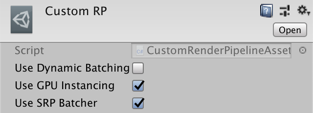
It is now possible to change which approaches are used by our RP. Toggling an option will have immediate effect, as the Unity editor will create a new RP instance when it detects that the asset is changed.
Transparency
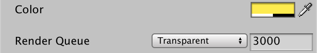
Our shader can be used to create unlit opaque materials. It is possible to change the alpha component of the color, which usually indicates transparency, but it currently has no effect. We can also set the render queue to Transparent, but this only changes when objects get drawn and in what order, not how.
We don't need to write a separate shader to support transparent materials. With a little work our Unlit shader can support both opaque and transparent rendering.
Blend Modes
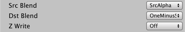
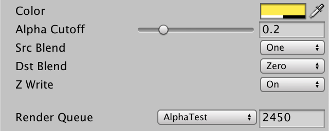
The main difference between opaque and transparent rendering is whether we replace anything that was drawn before or combine with the previous result to produce a see-through effect. We can control this by setting the source and destination blend modes. Here source refers to what gets drawn now and destination to what was drawn earlier and where the result will end up. Add two shader properties for this: _SrcBlend and _DstBlend. They're enumerations for blend modes, but the best type we can use is Float, set to 1 for the source and zero for the destination by default.
	Properties {
		_BaseColor("Color", Color) = (1.0, 1.0, 1.0, 1.0)
		_SrcBlend ("Src Blend", Float) = 1
		_DstBlend ("Dst Blend", Float) = 0
	}
To make editing easier we can add the Enum attribute to the properties, with the fully-qualified UnityEngine.Rendering.BlendMode enum type as an argument.
		[Enum(UnityEngine.Rendering.BlendMode)] _SrcBlend ("Src Blend", Float) = 1
		[Enum(UnityEngine.Rendering.BlendMode)] _DstBlend ("Dst Blend", Float) = 0
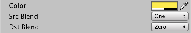
The default values represent the opaque blend configuration that we were already using. The source is set to 1, meaning it gets added in full, while the destination is set to zero, meaning that it gets ignored.
The source blend mode for standard transparency is SrcAlpha, which means that the RGB components of the rendered color get multiplied by its alpha component. So the lower alpha is the weaker it gets. The destination blend mode is then set to the reverse: OneMinusSrcAlpha, to arrive at a total weight of 1.
The blend modes can be defined in the Pass block with the Blend statement followed by the two modes. We want to use the shader properties, which we can access here by putting them inside square brackets. This is old syntax from the days before programmable shaders.
		Pass {
			Blend [_SrcBlend] [_DstBlend]

			HLSLPROGRAM
			…
			ENDHLSL
		}
Not Writing Depth
Transparent rendering usually doesn't write to the depth buffer because it doesn't benefit from it and might even produce undesired results. We can control whether depth is written or not via the ZWrite statement. Again we can use a shader property, this time using _ZWrite.
			Blend [_SrcBlend] [_DstBlend]
			ZWrite [_ZWrite]
Define the shader property with a custom Enum(Off, 0, On, 1) attribute to create an on-off toggle with the values 0 and 1 that is on by default.
		[Enum(UnityEngine.Rendering.BlendMode)] _SrcBlend ("Src Blend", Float) = 1
		[Enum(UnityEngine.Rendering.BlendMode)] _DstBlend ("Dst Blend", Float) = 0
		[Enum(Off, 0, On, 1)] _ZWrite ("Z Write", Float) = 1
Texturing
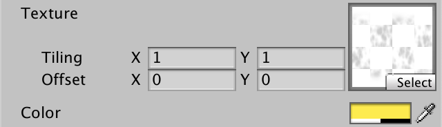
Previously we used an alpha map to create a nonuniform semitransparent material. Let's support that as well, by adding a _BaseMap texture property to the shader. In this case the type is 2D and we'll use Unity's standard white texture as the default, indicated with the white string. Also, we have to end the texture property with an empty code block. It was used to control the texture settings long ago, but should still be included today to prevent weird errors in some cases.
		_BaseMap("Texture", 2D) = "white" {}
		_BaseColor("Color", Color) = (1.0, 1.0, 1.0, 1.0)
Textures have to be uploaded to GPU memory, which Unity does for us. The shader needs a handle to a relevant texture, which we can define like a uniform value, except we use the TEXTURE2D macro with the name as an argument. We also need to define a sampler state for the texture, which controls how it should be sampled, considering its wrap and filter modes. That's done with the SAMPLER macro, like TEXTURE2D but with sampler prepended to the name. That matches the name of the sampler state that Unity provides automatically.
Textures and sampler states are shader resources. The cannot be provided per instance and have to be declared in the global scope. Do this before the shader properties in UnlitPass.hlsl.
TEXTURE2D(_BaseMap);
SAMPLER(sampler_BaseMap);

UNITY_INSTANCING_BUFFER_START(UnityPerMaterial)
	UNITY_DEFINE_INSTANCED_PROP(float4, _BaseColor)
UNITY_INSTANCING_BUFFER_END(UnityPerMaterial)
Besides that, Unity also makes the tiling and offset of the texture available via a float4 that has the same name as the texture property but with _ST appended, which stands for scale and translation or something like that. This property should be part of the UnityPerMaterial buffer and thus can be set per instance.
UNITY_INSTANCING_BUFFER_START(UnityPerMaterial)
	UNITY_DEFINE_INSTANCED_PROP(float4, _BaseMap_ST)
	UNITY_DEFINE_INSTANCED_PROP(float4, _BaseColor)
UNITY_INSTANCING_BUFFER_END(UnityPerMaterial)
To sample the texture we need texture coordinates, which are part of the vertex attributes. Specifically, we needs the first pair of coordinates, as there could be more. That's done by adding a float2 field with the TEXCOORD0 meaning to Attributes. As it's for our base map and the texture space dimensions are universally named U and V we'll name it baseUV.
struct Attributes {
	float3 positionOS : POSITION;
	float2 baseUV : TEXCOORD0;
	UNITY_VERTEX_INPUT_INSTANCE_ID
};
We need to pass the coordinates to the fragment function as it is there that the texture is sampled. So add float2 baseUV to Varyings as well. This time we do not need to add a special meaning, it's just data that we pass along that doesn't require special attention from the GPU. However, we still have to attach some meaning to it. We could apply any unused identifier, let's simply use VAR_BASE_UV.
struct Varyings {
	float4 positionCS : SV_POSITION;
	float2 baseUV : VAR_BASE_UV;
	UNITY_VERTEX_INPUT_INSTANCE_ID
};
When we copy the coordinates in UnlitPassVertex we can also apply the scale and offset stored in _BaseMap_ST. That way we do it per vertex instead of per fragment. The scale is stored in XY and the offset in ZW, which we can access via swizzle properties.
Varyings UnlitPassVertex (Attributes input) {
	…

	float4 baseST = UNITY_ACCESS_INSTANCED_PROP(UnityPerMaterial, _BaseMap_ST);
	output.baseUV = input.baseUV * baseST.xy + baseST.zw;
	return output;
}
The UV coordinates are now available to UnlitPassFragment, interpolated across the triangle. Sample the texture here, by using the SAMPLE_TEXTURE2D macro with the texture, sampler state, and coordinates as arguments. The final color is the texture and uniform color combined via multiplication. Multiplying two same-size vectors results in all matching components getting multiplied, so in this case red times red, green times green, and so on.
float4 UnlitPassFragment (Varyings input) : SV_TARGET {
	UNITY_SETUP_INSTANCE_ID(input);
	float4 baseMap = SAMPLE_TEXTURE2D(_BaseMap, sampler_BaseMap, input.baseUV);
	float4 baseColor = UNITY_ACCESS_INSTANCED_PROP(UnityPerMaterial, _BaseColor);
	return baseMap * baseColor;
}

Because the RGB data of our texture is uniform white the color is not affected. But the alpha channel varies, so transparency is no longer uniform.
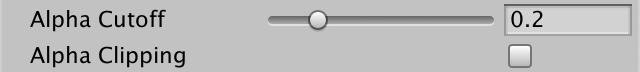
Alpha Clipping
Another way to see through surfaces is by cutting holes in them. Shaders can do that as well, by discarding some of the fragments that they would normally render. That produces hard edges instead of the smooth transitions that we currently see. This technique is know as alpha clipping. The usual ways that this is done is by defining a cutoff threshold. Fragments with alpha values below this threshold are to be discarded while all others are kept.
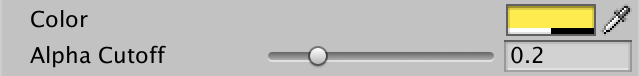
Add a _Cutoff property that is set to 0.5 by default. As alpha always lies between zero and 1 we can use Range(0.0, 1.0) as its type.
		_BaseColor("Color", Color) = (1.0, 1.0, 1.0, 1.0)
		_Cutoff ("Alpha Cutoff", Range(0.0, 1.0)) = 0.5
Add it to the material properties in UnlitPass.hlsl as well.
	UNITY_DEFINE_INSTANCED_PROP(float4, _BaseColor)
	UNITY_DEFINE_INSTANCED_PROP(float, _Cutoff)
We can discard fragments by invoking the clip function in UnlitPassFragment. It will abort and discard the fragment if the value we pass it is zero or less. So pass it the final alpha value—accessible via either the a or w property—minus the cutoff threshold.
	float4 baseMap = SAMPLE_TEXTURE2D(_BaseMap, sampler_BaseMap, input.baseUV);
	float4 baseColor = UNITY_ACCESS_INSTANCED_PROP(UnityPerMaterial, _BaseColor);
	float4 base = baseMap * baseColor;
	clip(base.a - UNITY_ACCESS_INSTANCED_PROP(UnityPerMaterial, _Cutoff));
	return base;
A material usually uses either transparency blending or alpha clipping, not both at the same time. A typical clip material is fully opaque except for the discarded fragments and does write to the depth buffer. It uses the AlphaTest render queue, which means that it gets rendered after all fully opaque objects. This is done because discarding fragments makes some GPU optimizations impossible, as triangles can no longer be assumed to entirely cover what's behind them. By drawing fully opaque objects first they might end up covering part of the alpha-clipped objects, which then don't need to process their hidden fragments.
But to make this optimization work we have to make sure that clip is only used when needed. We'll do that by adding a feature toggle shader property. It's a Float property set to zero by default, with a Toggle attribute that controls a shader keyword, for which we'll use _CLIPPING. The name of the property itself doesn't matter, so simply use _Clipping.
		_Cutoff ("Alpha Cutoff", Range(0.0, 1.0)) = 0.5
		[Toggle(_CLIPPING)] _Clipping ("Alpha Clipping", Float) = 0
Shader Features
Enabling the toggle will add the _CLIPPING keyword to the material's list of active keywords, while disabling will remove it. But that doesn't do anything on its own. We have to tell Unity to compile a different version of our shader based on whether the keyword is defined or not. We do that by adding #pragma shader_feature _CLIPPING to the directives in its Pass.
			#pragma shader_feature _CLIPPING
			#pragma multi_compile_instancing
Now Unity will compile our shader code either with or without _CLIPPING defined. It will generate one or both variants, depending on how we configured our materials. So we can make our code conditional on the definition, just like include guards, but in this case we only want to include the clipping line when _CLIPPING is defined. We could use #ifdef _CLIPPING for that, but I prefer #if defined(_CLIPPING).
	#if defined(_CLIPPING)
		clip(base.a - UNITY_ACCESS_INSTANCED_PROP(UnityPerMaterial, _Cutoff));
	#endif
Cutoff Per Object
As the cutoff is part of the UnityPerMaterial buffer it can be configured per instance. So let's add that functionality to PerObjectMaterialProperties. It works the same as for the color, except that we need to invoke SetFloat instead of SetColor on the property block.
	static int baseColorId = Shader.PropertyToID("_BaseColor");
	static int cutoffId = Shader.PropertyToID("_Cutoff");

	static MaterialPropertyBlock block;

	[SerializeField]
	Color baseColor = Color.white;

	[SerializeField, Range(0f, 1f)]
	float cutoff = 0.5f;

	…

	void OnValidate () {
		…
		block.SetColor(baseColorId, baseColor);
		block.SetFloat(cutoffId, cutoff);
		GetComponent<Renderer>().SetPropertyBlock(block);
	}
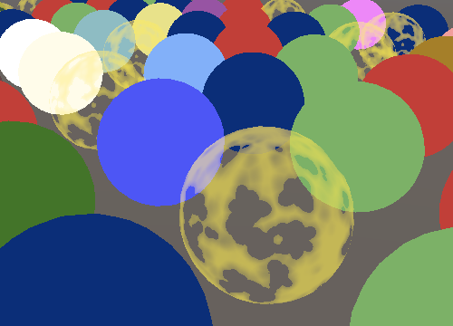
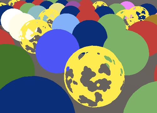
Ball of Alpha-Clipped Spheres
The same is true for MeshBall. Right now we can use a clip material, but all instances end up with the exact same holes.

Let's add some variety by giving each instance a random rotation, plus a random uniform scale within the 0.5–1.5 range. But rather than setting the cutoff per instance we'll vary their color's alpha channel in the 0.5–1 range instead. That gives us less precise control, but it's a random example anyway.
			matrices[i] = Matrix4x4.TRS(
				Random.insideUnitSphere * 10f,
				Quaternion.Euler(
					Random.value * 360f, Random.value * 360f, Random.value * 360f
				),
				Vector3.one * Random.Range(0.5f, 1.5f)
			);
			baseColors[i] =
				new Vector4(
					Random.value, Random.value, Random.value,
					Random.Range(0.5f, 1f)
				);
Note that Unity still ends up sending an array of cutoff values to the GPU, one per instance, even if they are all the same. The value is a copy of the material's, so by varying that it's possible to change the holes of all spheres at once, even though they are still different.
The next tutorial is Directional Lights.