LOD and Reflections
Adding Details
- Use LOD Groups.
- Cross-Fade between LOD levels.
- Reflect the environment by sampling a reflection probe.
- Support optional Fresnel reflections.
This is the seventh part of a tutorial series about creating a custom scriptable render pipeline. It cover level-of-detail hierarchies and simple reflections, which can add details to our scenes.
This tutorial is made with Unity 2019.2.21f1 and upgraded to 2022.3.5f1.
LOD Groups
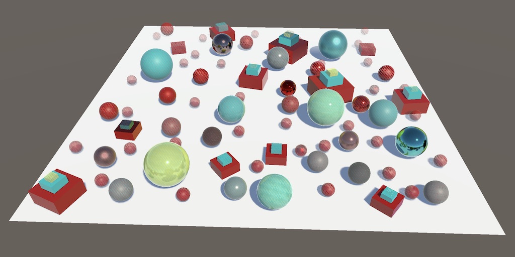
Many small objects add details to a scene and make it more interesting. However, details that are too small to cover multiple pixels degrade into indistinct noise. At those visual scales it's better to not render them, which also frees up the CPU and GPU to render more important things. We can also decide to cull such objects earlier, when they could still be distinguished. That improves performance even more, but causes things to suddenly pop in and out of existence based on their visual size. We could also add intermediate steps, switching to successively less-detailed visualizations before eventually completely culling an object. Unity makes it possible to do all these things by using LOD Groups.
LOD Group Component
You can add a level-of-detail group to a scene by creating an empty game object and adding a LODGroup component to it. The default group defines four levels: LOD 0, LOD 1, LOD 2, and finally culled, which means that nothing gets rendered. The percentages represent thresholds for estimated visual size, relative to the display window dimensions. So LOD 0 is used for objects covering more than 60% of the window, typically considering the vertical dimension as that's the smallest.
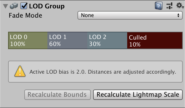
However, the Quality project settings section contains a LOD Bias which scales these thresholds. It's set to 2 by default, which means it doubles the estimates visual size for this assessment. Thus LOD 0 ends up used for everything above 30% instead of only 60%. The component's inspector displays a warning when the bias is set to something other than 1. Besides that there's also a Maximum LOD Level option which can be used to limit the highest LOD level. For example if it were set to 1 then LOD 1 would also be used instead of LOD 0.
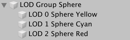
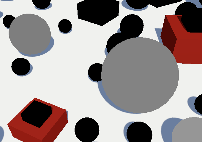
The idea is that you make all game objects that visualize LOD levels children of the group object. For example, I used three colored spheres of the same size for the three LOD levels.
Each objects has to be assigned to the appropriate LOD level. You can do this by selecting a level block in the group component and then dragging the object onto its Renderers list, or by dropping it directly on a LOD level block.
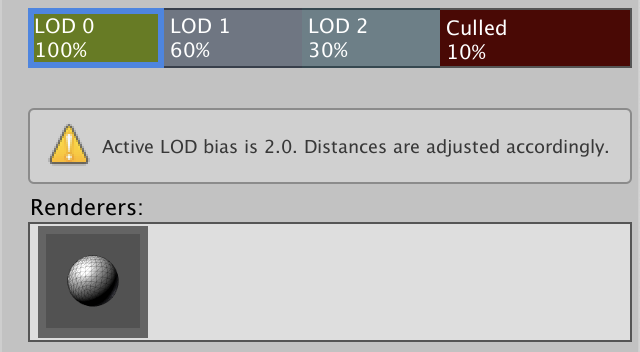
Unity will automatically render the appropriate objects. Selecting a specific object in the editor will override this behavior, so you can see your selection in the scene. If you have a LOD group itself selected the editor will also indicate which LOD level is currently visible.
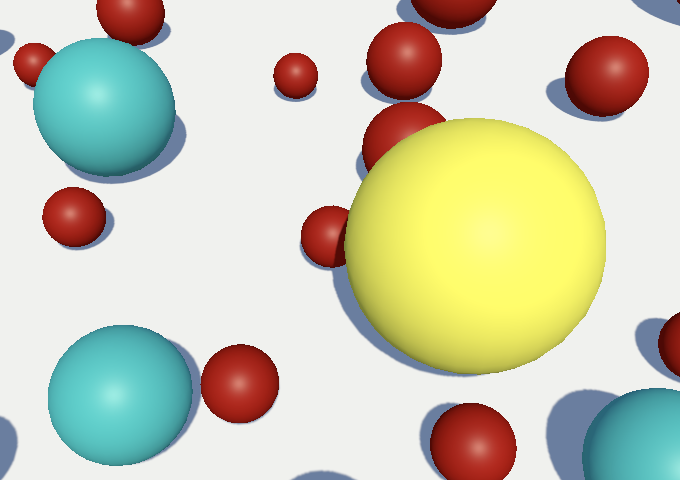
Moving the camera around will change which LOD levels get used for each group. Alternatively, you can adjust the LOD bias to see the visualizations change while keeping everything else the same.
Additive LOD Groups
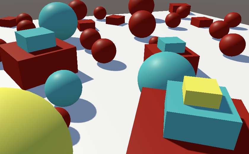
Objects can be added to more than one LOD level. You can use this to add smaller details to higher levels while the same bigger objects are used for multiple levels. For example, I made a three-step pyramid from stacked flattened cubes. The base cube is part of all three levels. The middle cube is part of LOD 0 and LOD 1, while the smallest top cube is only part of LOD 0. Thus details and added and removed to the group based on visual size, instead of replacing the entire thing.
LOD Transitions
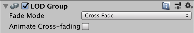
The sudden swap of LOD levels can be visually jarring, especially if an object ends up switching back and forth in rapid succession due to slight movement of either itself or the camera. It is possible to make this transition gradual, by setting the group's Fade Mode to Cross Fade. This makes the old level fade out while the new level fades in at the same time.
You can control per LOD level when the cross-fade to the next level starts. This option becomes visible when cross-fading is enabled. A Fade Transition Width of zero means no fading between this level and the next lower, while a value of 1 means it starts fading immediately. At 0.5, with default settings LOD 0 would begin cross-fading to LOD 1 at 80%.
When cross-fading is active both LOD levels get rendered at the same time. It's up to the shader to blend them somehow. Unity picks a shader variant for the LOD_FADE_CROSSFADE keyword, so add a multi-compile directive for it to our Lit shader. Do this for both the CustomLit and the ShadowCaster passes.
#pragma multi_compile _ LOD_FADE_CROSSFADE
How much an object is faded gets communicated via the unity_LODFade vector of the UnityPerDraw buffer, which we've already defined. Its X component contains the fade factor. Its Y component contains the same factor, but quantized to sixteen steps, which we won't use. Let's visualize the fade factor if it is in use by returning it at the start of LitPassFragment.
float4 LitPassFragment (Varyings input) : SV_TARGET {
	UNITY_SETUP_INSTANCE_ID(input);
	#if defined(LOD_FADE_CROSSFADE)
		return unity_LODFade.x;
	#endif

	…
}
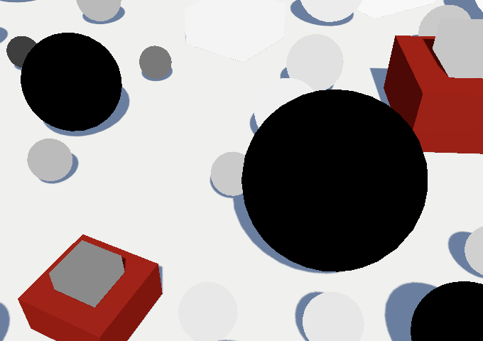
Objects that are fading out start with a factor of 1 and reduces to zero, as expected. But we also see solid black objects that represent higher LOD levels. That happens because objects that are fading in have their fade factor negated. We can see this by returning the negated fade factor instead.
return -unity_LODFade.x;
Note that objects that are in both LOD levels aren't cross-faded with themselves.
Dithering
To mix both LOD levels we can use clipping, applying an approach similar to approximating semitransparent shadows. As we need to do this for both surfaces and their shadows, let's add a ClipLOD function for this to Common. Give it clip-space XY coordinates and the fade factor as parameters. Then—if cross-fading is active—clip based on the fade factor minus a dither pattern.
void ClipLOD (float2 positionCS, float fade) {
	#if defined(LOD_FADE_CROSSFADE)
		float dither = 0;
		clip(fade - dither);
	#endif
}
To check whether clipping works as expected, we'll start with a vertical gradient that repeats every 32 pixels. That should create alternating horizontal stripes.
float dither = (positionCS.y % 32) / 32;
Invoke ClipLOD in LitPassFragment instead of returning the fade factor.
//#if defined(LOD_FADE_CROSSFADE)// return unity_LODFade.x;//#endifClipLOD(input.positionCS.xy, unity_LODFade.x);
And also invoke it at the start of ShadowCasterPassFragment to cross-fade shadows.
void ShadowCasterPassFragment (Varyings input) {
	UNITY_SETUP_INSTANCE_ID(input);
	ClipLOD(input.positionCS.xy, unity_LODFade.x);

	…
}
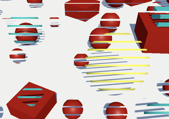
We get striped rendering, but only one of the two LOD levels shows up when cross-fading. That's because one of the two has a negative fade factor. We fix that by adding instead of subtracting the dither pattern when that's the case.
clip(fade + (fade < 0.0 ? dither : -dither));
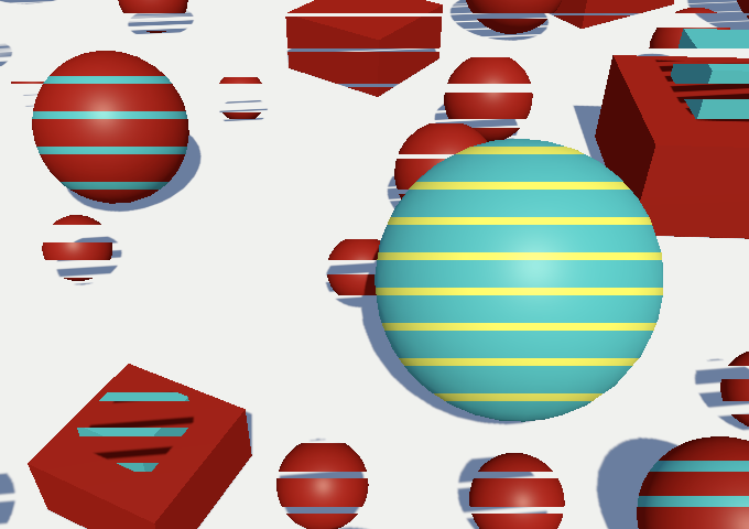
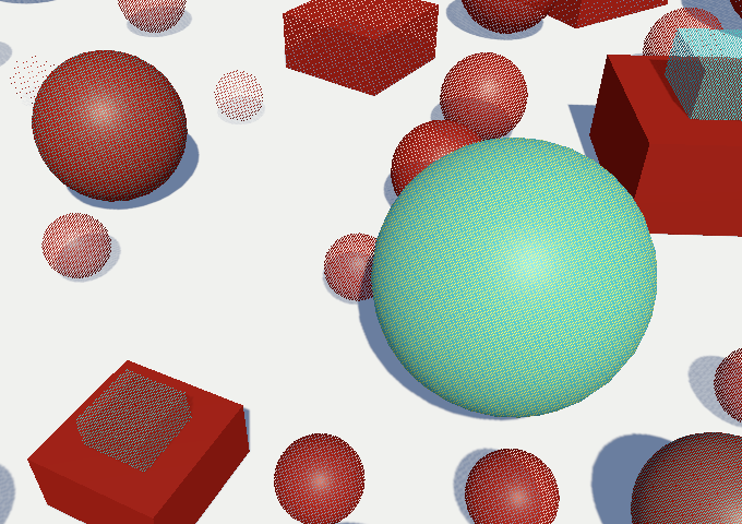
Now that it's working we can switch to a proper dither pattern. Let's pick the same one that we use for semitransparent shadows.
float dither = InterleavedGradientNoise(positionCS.xy, 0);
Animated Cross-Fading
Although dithering creates a fairly smooth transition, the pattern is obvious. And just like with semitransparent shadows, faded shadows are unstable and distracting. Ideally a cross-fade is only temporary, even then nothing else changes. We can make it so by enabling the LOD group's Animate Cross-fading option. That disregards fade transition widths and instead quickly cross-fades once a group passes a LOD threshold.

The default animation duration is half a second, which can be changed for all groups by setting the static LODGroup.crossFadeAnimationDuration property. However, while not in play mode the transitions are faster in Unity 2022.
Reflections
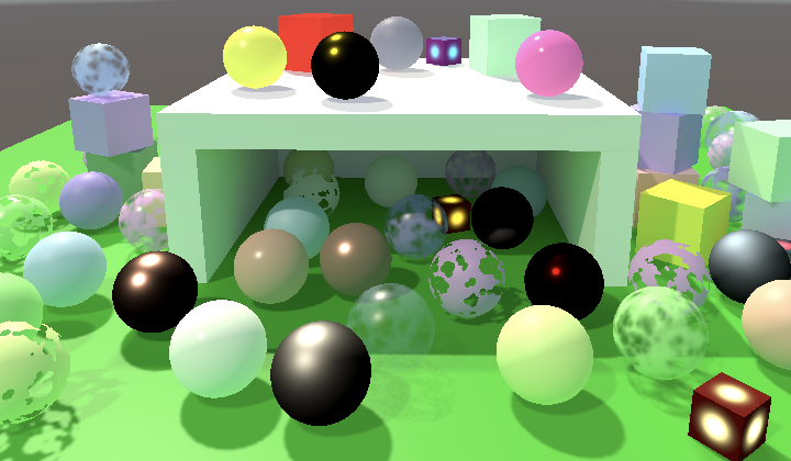
Another phenomenon that adds detail and realism to a scene is specular reflection of the environment—of which mirrors are the most obvious example—which we don't support yet. This is especially important for metallic surfaces, which are currently mostly black. To make this more obvious I added a new more metal spheres with varying color and smoothness to the Baked Light scene.
Indirect BRDF
We already support diffuse global illumination, which depends on the BRDF's diffuse color. Now we add specular global illumination as well, which also depends on the BRDF. So let's add an IndirectBRDF function to BRDF, with surface and BRDF parameters, plus diffuse and specular colors obtained from global illumination. Initially have it return the reflected diffuse light only.
float3 IndirectBRDF (
	Surface surface, BRDF brdf, float3 diffuse, float3 specular
) {
    return diffuse * brdf.diffuse;
}
Adding the specular reflection starts out similar: simply include the specular GI multiplied with the BRDF's specular color.
	float3 reflection = specular * brdf.specular;

    return diffuse * brdf.diffuse + reflection;
But roughness scatters this reflection, so it should reduce the specular reflection that we end up seeing. We do this by dividing it by the squared roughness plus one. Thus low roughness values don't matter much while maximum roughness halves the reflection.
	float3 reflection = specular * brdf.specular;
	reflection /= brdf.roughness * brdf.roughness + 1.0;
Invoke IndirectBRDF in GetLighting instead of calculating the diffuse indirect light directly. Start with using white for the specular GI color.
float3 GetLighting (Surface surfaceWS, BRDF brdf, GI gi) {
	ShadowData shadowData = GetShadowData(surfaceWS);
	shadowData.shadowMask = gi.shadowMask;

	float3 color = IndirectBRDF(surfaceWS, brdf, gi.diffuse, 1.0);
	for (int i = 0; i < GetDirectionalLightCount(); i++) {
		Light light = GetDirectionalLight(i, surfaceWS, shadowData);
		color += GetLighting(surfaceWS, brdf, light);
	}
	return color;
}
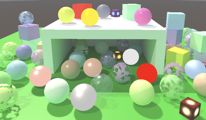
Everything got at least a little brighter, because we're adding lighting that was previously missing. The change to metallic surfaces is dramatic: their colors are now bright and obvious.
Sampling the Environment
Specular reflections mirror the environment, which is the skybox by default. It's made available as a cube map texture, via unity_SpecCube0. Declare it in GI along with its sampler state, this time using the TEXTURECUBE macro.
TEXTURECUBE(unity_SpecCube0);
SAMPLER(samplerunity_SpecCube0);
Then add a SampleEnvironment function with a world-space surface parameter, sample the texture, and return its RGB components. We sample the cube map via the SAMPLE_TEXTURECUBE_LOD macro, which takes the map, sampler state, UVW coordinates, and mip level as arguments. As it's a cube map we need 3D texture coordinates, hence UVW. We start with always using the highest mip level, so we sample the full-resolution texture.
float3 SampleEnvironment (Surface surfaceWS) {
	float3 uvw = 0.0;
	float4 environment = SAMPLE_TEXTURECUBE_LOD(
		unity_SpecCube0, samplerunity_SpecCube0, uvw, 0.0
	);
	return environment.rgb;
}
Sampling a cube map is done with a direction, which in this case is the view direction from camera to surface reflected off the surface. We get it by invoking the reflect function with the negative view direction and the surface normal as arguments.
float3 uvw = reflect(-surfaceWS.viewDirection, surfaceWS.normal);
Next, add a specular color to GI and store the sampled environment in it in GetGI.
struct GI {
	float3 diffuse;
	float3 specular;
	ShadowMask shadowMask;
};

…

GI GetGI (float2 lightMapUV, Surface surfaceWS) {
	GI gi;
	gi.diffuse = SampleLightMap(lightMapUV) + SampleLightProbe(surfaceWS);
	gi.specular = SampleEnvironment(surfaceWS);
	…
}
Now we can pass the correct color to IndirectBRDF in GetLighting.
float3 color = IndirectBRDF(surfaceWS, brdf, gi.diffuse, gi.specular);
Finally, to get it working we have to instruct Unity to include the reflection probe when setting up the per-object data, in CameraRenderer.DrawVisibleGeometry.
			perObjectData =
				PerObjectData.ReflectionProbes |
				PerObjectData.Lightmaps | PerObjectData.ShadowMask |
				PerObjectData.LightProbe | PerObjectData.OcclusionProbe |
				PerObjectData.LightProbeProxyVolume |
				PerObjectData.OcclusionProbeProxyVolume
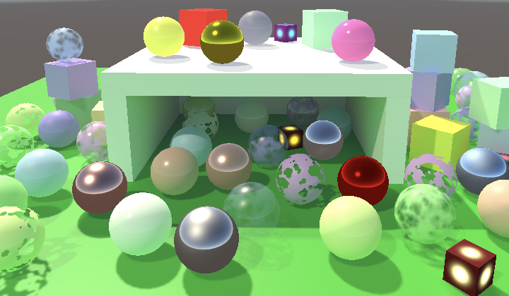
Surfaces now reflect the environment. This is obvious for metallic surfaces but other surfaces reflect it as well. As it's just the sky box nothing else gets reflected, but we'll look at that later.
Rough Reflections
As roughness scatters specular reflection it not only reduces its intensity but also muddles it, as if it's out of focus. This effect gets approximated by Unity by storing blurred versions of the environment map in lower mip levels. To access the correct mip level we need to know the perceptual roughness, so let's add it to the BRDF struct.
struct BRDF {
	…
	float perceptualRoughness;
};

…

BRDF GetBRDF (Surface surface, bool applyAlphaToDiffuse = false) {
	…

	brdf.perceptualRoughness =
		PerceptualSmoothnessToPerceptualRoughness(surface.smoothness);
	brdf.roughness = PerceptualRoughnessToRoughness(brdf.perceptualRoughness);
	return brdf;
}
We can rely on the PerceptualRoughnessToMipmapLevel function to calculate the correct mip level for a given perceptual roughness. It's defined in the ImageBasedLighting file of the Core RP Library. This requires us to add a BRDF parameter to SampleEnvironment.
#include "Packages/com.unity.render-pipelines.core/ShaderLibrary/EntityLighting.hlsl"
#include "Packages/com.unity.render-pipelines.core/ShaderLibrary/ImageBasedLighting.hlsl"

…

float3 SampleEnvironment (Surface surfaceWS, BRDF brdf) {
	float3 uvw = reflect(-surfaceWS.viewDirection, surfaceWS.normal);
	float mip = PerceptualRoughnessToMipmapLevel(brdf.perceptualRoughness);
	float4 environment = SAMPLE_TEXTURECUBE_LOD(
		unity_SpecCube0, samplerunity_SpecCube0, uvw, mip
	);
	return environment.rgb;
}
Add the required parameter to GetGI as well and pass it through.
GI GetGI (float2 lightMapUV, Surface surfaceWS, BRDF brdf) {
	GI gi;
	gi.diffuse = SampleLightMap(lightMapUV) + SampleLightProbe(surfaceWS);
	gi.specular = SampleEnvironment(surfaceWS, brdf);
	…
}
Finally, supply it in LitPassFragment.
GI gi = GetGI(GI_FRAGMENT_DATA(input), surface, brdf);
Fresnel Reflection
A property of all surfaces is that when viewed at grazing angles they start to resemble perfect mirrors, as light bounces off them mostly unaffected. This phenomenon is known as Fresnel reflection. It's actually more complicated than that as it has to do with transmission and reflection of light waves at the boundaries of different media, but we simply use the same approximation that the Universal RP uses, which is to assume air-solid boundaries.
We use a variant Schlick's approximation for Fresnel. It replaces the specular BRDF color with solid white in the ideal case, but roughness can prevent reflections from showing up. We arrive at the final color by adding the surface smoothness and reflectivity together, with a maximum of 1. As it's grayscale we can suffice with adding a single value to BRDF for it.
struct BRDF {
	…
	float fresnel;
};

…

BRDF GetBRDF (Surface surface, bool applyAlphaToDiffuse = false) {
	…

	brdf.fresnel = saturate(surface.smoothness + 1.0 - oneMinusReflectivity);
	return brdf;
}
In IndirectBRDF we find the strength of the Fresnel effect by taking the dot product of the surface normal and view direction, subtracting it from 1, and raising the result to the fourth power. We can use the convenient Pow4 function from the Core RP Library here.
	float fresnelStrength =
		Pow4(1.0 - saturate(dot(surface.normal, surface.viewDirection)));
	float3 reflection = specular * brdf.specular;
We then interpolate between the BRDF specular and fresnel color based on the strength, then use the result of tint the environment reflection.
	float3 reflection =
		specular * lerp(brdf.specular, brdf.fresnel, fresnelStrength);
Fresnel Slider
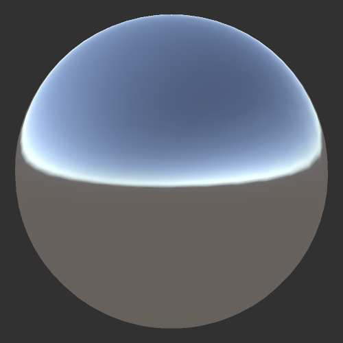
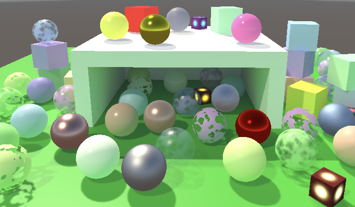
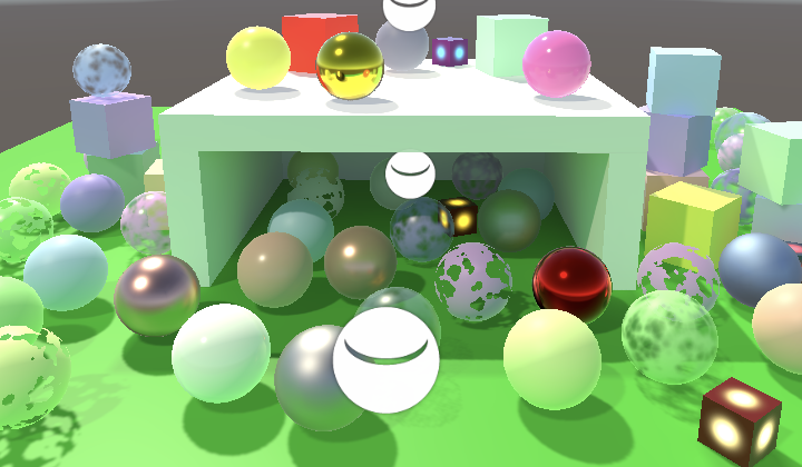
Fresnel reflections add reflections mostly along the edges of geometry. The effect is subtle when the environment map correctly matches the color of what's behind the object, but if that's not the case the reflections can appear weird and distracting. The bright reflections along the edges of spheres inside the structure are a good example.
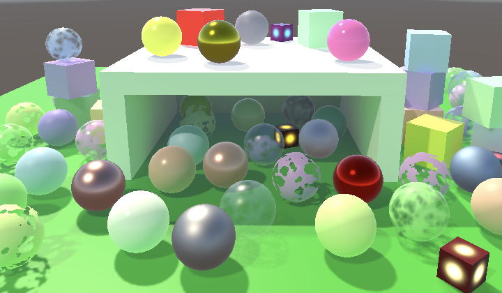
Lowering smoothness gets rid of Fresnel reflections, but dulls the entire surface as well. Also, in some cases the Fresnel approximation isn't appropriate, for example underwater. So let's add a slider to scale it down to the Lit shader.
		_Metallic ("Metallic", Range(0, 1)) = 0
		_Smoothness ("Smoothness", Range(0, 1)) = 0.5
		_Fresnel ("Fresnel", Range(0, 1)) = 1
Add it to the UnityPerMaterial buffer in LitInput and create a GetFresnel function for it.
UNITY_INSTANCING_BUFFER_START(UnityPerMaterial)
	…
	UNITY_DEFINE_INSTANCED_PROP(float, _Fresnel)
UNITY_INSTANCING_BUFFER_END(UnityPerMaterial)

…

float GetFresnel (float2 baseUV) {
	return UNITY_ACCESS_INSTANCED_PROP(UnityPerMaterial, _Fresnel);
}
Also add a dummy function for it to UnlitInput, to keep them synchronized.
float GetFresnel (float2 baseUV) {
	return 0.0;
}
Surface now gets a field for its Fresnel strength.
struct Surface {
	…
	float smoothness;
	float fresnelStrength;
	float dither;
};
Which we set equal to the slider poperty's value in LitPassFragment.
	surface.smoothness = GetSmoothness(input.baseUV);
	surface.fresnelStrength = GetFresnel(input.baseUV);
Finally, use it to scale the Fresnel strength that we use in IndirectBRDF.
	float fresnelStrength = surface.fresnelStrength *
		Pow4(1.0 - saturate(dot(surface.normal, surface.viewDirection)));
Reflection Probes
The default environment cube map only contains the sky box. To reflect anything else in the scene we have to add a reflection probe to it, via GameObject / Light / Reflection Probe. These probes render the scene to a cube map, from their position. So reflections will only appear more-or-less correct for surfaces that are close to the probes. Thus it is often necessary to put multiple probes in a scene. They have Importance and Box Size properties that can be used to control which area is affected by each probe.
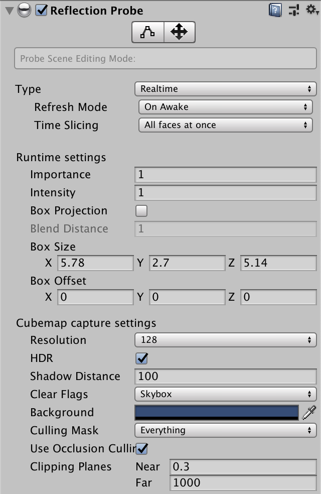
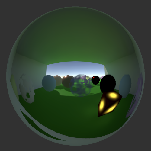
A probe's Type is set to Baked by default, which means that it gets rendered once and the cube map gets stored in builds. You could also set it to Realtime, which keeps the map up to date with the dynamic scene. It gets rendered just like any other camera, using our RP, once for each of the six faces of the cube map. So realtime reflection probes are expensive.
Only a single environment probe is used per object, but there can be multiple probes in the scene. Thus you might have to split objects to get acceptable reflections. For example, the cubes used to build the structure should ideally be split into separate inside and outside parts, so each could use a different reflection probe. Also, this means that GPU batching gets broken up by reflection probes. Unfortunately the mesh ball can't use reflection probes at all, always ending up with the sky box.
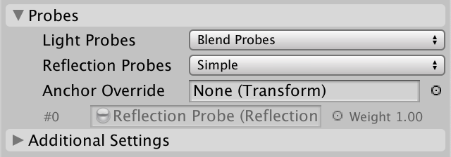
MeshRenderer components have an Anchor Override that can be used to fine-tune which probe they use, without having to worry about box sizes and positions. There's also a Reflection Probes option, which is set to Blend Probes by default. The idea is that Unity allows blending between the best two reflection probes. However, this mode in incompatible with the SRP batcher, so Unity's other RPs don't support it and neither will we. In case you're curious, how to blend probes is explained in the Reflections tutorial of my 2018 SRP tutorial, but I expect this functionality to disappear once the legacy pipeline gets removed. We'll investigate other reflection techniques in the future. So the only two functional modes are Off, which always uses the sky box, and Simple, which picks the most important probe. The others functions exactly like Simple.
Besides that, reflection probes also have an option to enable box projection mode. This should change how reflections are determined to better match their finite influence area, but this also isn't supported by the SRP batcher so we won't support it either.
Decoding Probes
Finally, we have to make sure that we interpret the data from the cube map correctly. It could be HDR or LDR, and its intensity can also be adjusted. These settings are made available via the unity_SpecCube0_HDR vector, which comes after unity_ProbesOcclusion in the UnityPerDraw buffer.
CBUFFER_START(UnityPerDraw)
	…

	float4 unity_ProbesOcclusion;

	float4 unity_SpecCube0_HDR;

	…
CBUFFER_END
We get the correct color by invoking DecodeHDREnvironment with the raw environment data and the settings as arguments, at the end of SampleEnvironment.
float3 SampleEnvironment (Surface surfaceWS, BRDF brdf) {
	…
	return DecodeHDREnvironment(environment, unity_SpecCube0_HDR);
}
The next tutorial is Complex Maps.