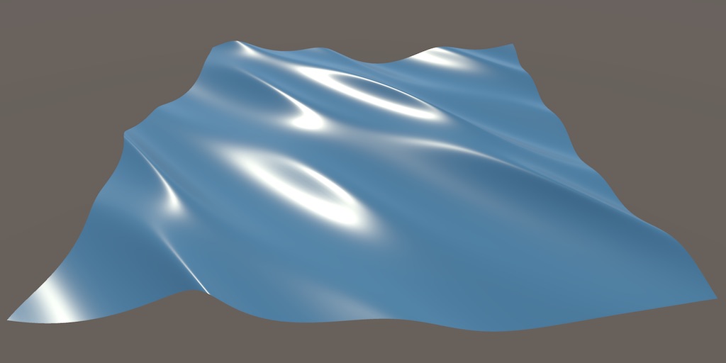
Waves
Moving Vertices
- Animate vertices.
- Create Gerstner waves.
- Control wave direction.
- Combine multiple waves.
This is the third tutorial in a series about creating the appearance of flowing materials. While the previous two parts deal with animating surface textures, this one is about creating waves by animating vertex positions.
This tutorial is made with Unity 2017.4.4f1.
Sine Waves
Animating textures can create the illusion of a moving surface, but the mesh surface itself remains motionless. This is fine for small ripples, but cannot represent larger waves. On large bodies of water—like an ocean of big lake—the wind can create big waves that can persist for a long time. To represent these wind waves, we'll make new shader that displaces mesh vertices vertically, using a sine wave function.
Adjusting Vertices
Create a new surface shader named Waves. We'll leave the fragment surface function unchanged. Instead, add another function vert to adjust the vertex data. This function has a single vertex parameter, both for input and output. We'll use Unity's default vertex data structure, appdata_full.
Shader "Custom/Waves" {
	Properties {
		_Color ("Color", Color) = (1,1,1,1)
		_MainTex ("Albedo (RGB)", 2D) = "white" {}
		_Glossiness ("Smoothness", Range(0,1)) = 0.5
		_Metallic ("Metallic", Range(0,1)) = 0.0
	}
	SubShader {
		Tags { "RenderType"="Opaque" }
		LOD 200

		CGPROGRAM
		#pragma surface surf Standard fullforwardshadows
		#pragma target 3.0

		sampler2D _MainTex;

		struct Input {
			float2 uv_MainTex;
		};

		half _Glossiness;
		half _Metallic;
		fixed4 _Color;

		void vert(inout appdata_full vertexData) {}

		void surf (Input IN, inout SurfaceOutputStandard o) {
			fixed4 c = tex2D (_MainTex, IN.uv_MainTex) * _Color;
			o.Albedo = c.rgb;
			o.Metallic = _Metallic;
			o.Smoothness = _Glossiness;
			o.Alpha = c.a;
		}
		ENDCG
	}
	FallBack "Diffuse"
}
To indicate that the surface shader should use the vertex function, add vertex:vert to the surface pragma directive.
#pragma surface surf Standard fullforwardshadows vertex:vert
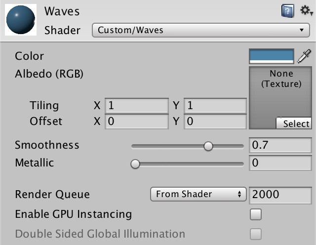
Create a new Waves material that uses this shader. I've given it the same albedo and smoothness as our other two materials.
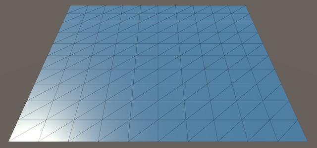
Because we're going to displaces vertices, we cannot make do with a quad this time. Instead, create a default plane via GameObject / 3D Object / Plane and have it use the Waves material. This gives us a grid of 10×10 quads to work with.
Adjusting Y
Ignoring the Z dimension for now, the position of each vertex can be defined as `P = [[x],[y]]`, where `P` is its final position, `x` is the original X coordinate, and `y` is the original Y coordinate, both in object space.
To create a wave, we have to adjust the Y component of `P`. The simplest way to make a wave is to use a sine wave based on `x`, so `y = sin x`. The final point is then `P = [[x],[sin x]]`.
		void vert(inout appdata_full vertexData) {
			float3 p = vertexData.vertex.xyz;

			p.y = sin(p.x);

			vertexData.vertex.xyz = p;
		}
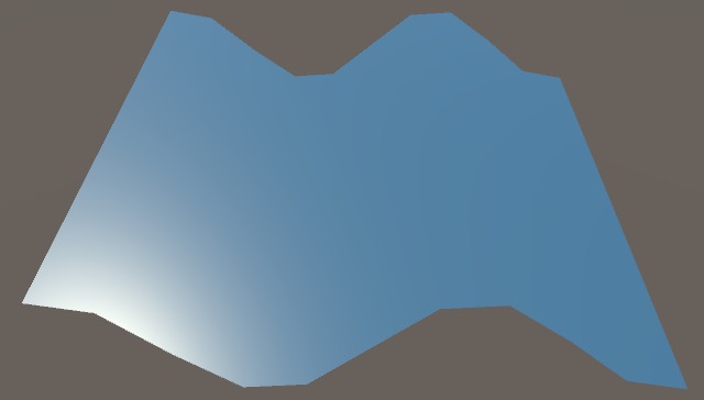
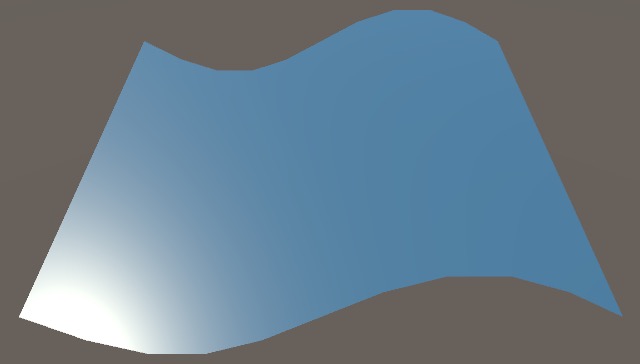
The result is a sine wave along the X dimension, which is constant along the Z dimension. The quads of the plane are of unit size, so the entire plane covers a 10×10 area centered on its local origin. So we end up seeing `10/(2pi)~~1.59` periods of a sine wave.
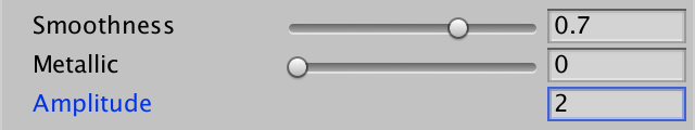
Amplitude
The default amplitude of a sine wave is 1, but we don't need to limit ourselves to that. Let's add a property to our shader so we can use `P_y = a sin x` instead, where `a` is the amplitude.
	Properties {
		…
		_Amplitude ("Amplitude", Float) = 1
	}
	SubShader {
		…

		half _Glossiness;
		half _Metallic;
		fixed4 _Color;
		float _Amplitude;

		void vert(inout appdata_full vertexData) {
			float3 p = vertexData.vertex.xyz;

			p.y = _Amplitude * sin(p.x);

			vertexData.vertex.xyz = p;
		}

		…
	}

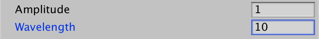
Wavelength
In the case of `sin x`, the length of a full sine wave is `2pi~~6.28`. This is the wavelength and let's make it configurable too.
To easily control the wavelength, we first have to multiply `x` by `2pi` then divide by the desired wavelength. So we end up with `sin((2pix)/lambda)`, where `lambda` (lambda) is the wavelength.
`2pi` divided by `lambda` is known as the wave number `k=(2pi)/lambda`. We could use this as the shader property, so we don't need to perform a division in the shader. That's a useful optimization, but in this tutorial we'll stick with the more user-friendly wavelength.
Inside the shader, we will explicitly use the wave number, so we end up with `P_y=asin(kx)`.
Shader "Custom/Waves" {
Properties {
…
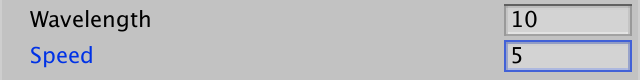
_Wavelength ("Wavelength", Float) = 10
}
SubShader {
…
float _Amplitude, _Wavelength;
void vert(inout appdata_full vertexData) {
float3 p = vertexData.vertex.xyz;
float k = 2 * UNITY_PI / _Wavelength;
p.y = _Amplitude * sin(k * p.x);
vertexData.vertex.xyz = p;
}
…
}
Speed
The wave needs to move, so we have to define a speed. It is most convenient to use the phase speed `c`, which defines how fast the entire wave moves in units per second. This is done by using the time offset `kct`. To make the wave move in the positive direction, we have to subtract this from `kx`, so we end up with `P_y=sin(kx-kct)=sin(k(x-ct))`.
	Properties {
		_Speed ("Speed", Float) = 1
	}
	SubShader {
		…
		float _Amplitude, _Wavelength, _Speed;

		void vert(inout appdata_full vertexData) {
			float3 p = vertexData.vertex.xyz;

			float k = 2 * UNITY_PI / _Wavelength;
			p.y = _Amplitude * sin(k * (p.x - _Speed * _Time.y));

			vertexData.vertex.xyz = p;
		}

		…
	}
Normal Vectors
Our surface is curved and moving, but the lighting is still that of a motionless flat plane. That's because we haven't changed the vertex normals yet. Instead of directly calculating the normal vector, let's first look at the surface tangent vector in the X dimension, `T`. For a flat surface `T=[[x^'],[0]]=[[1],[0]]`, which corresponds to the original plane's tangent. But for our wave we have to use `T=P^'=[[x^'],[asin(k(x-ct))^']]`.
The derivative of the sine is the cosine, so `sin^'x=cosx`. But the argument of the sine is a function itself in our case. We can say that we have `P_y=asinf`, where `f=k(x-ct)`.
We have to use the chain rule, `(P_y)^'=f^'acosf`. And `f^'=k`, so we end up with `T=[[1],[kacosf]]`. This makes sense, because changing the wavelength also changes the slope of the wave.
To get the final tangent vector in the shader, we have to normalize `T`.
			float k = 2 * UNITY_PI / _Wavelength;
			float f = k * (p.x - _Speed * _Time.y);
			p.y = _Amplitude * sin(f);

			float3 tangent = normalize(float3(1, k * _Amplitude * cos(f), 0));
The normal vector is the cross product of both tangent vectors. As our wave is constant in the Z dimension, the binormal is always the unit vector and can be ignored, so we end up with `N=[[-kacosf],[1]]`. We can just grab the normalized tangent components after normalizing them.
			float3 tangent = normalize(float3(1, k * _Amplitude * cos(f), 0));
			float3 normal = float3(-tangent.y, tangent.x, 0);

			vertexData.vertex.xyz = p;
			vertexData.normal = normal;
Mesh Resolution
While our wave looks fine when using a wavelength of 10, it won't work so well for small wavelengths. For example, a wavelength of 2 produces a standing sawtooth wave.
A wavelength of 1 produces no wave at all, instead the whole plane goes up and down uniformly. Other small wavelengths produce ugly waves that can even move backwards.
This problem is causes by the limited resolution of our plane mesh. Because vertices are spaces one unit apart, it cannot deal with wavelengths of 2 or smaller. In general, you have to keep the wavelength greater than twice the edge length of the triangles in your mesh. You don't want to cut it too close, because waves made up of two or three quads don't look good.
Either use larger wavelengths, or increase the resolution of your mesh. The simplest approach is to just use another mesh. Here is an alternative plane mesh that consists of 100×100 quads, instead of just 10×10. Each quad is still 1×1 unit, so you'll have to zoom out and multiply the wave properties by 10 to get the same result as before.
Shadows
Although our surface looks good, it doesn't correctly interact with shadows yet. It still acts like a flat plane, both for casting and receiving shadows.
The solution is to include addshadow in the surface pragma directive. That instructs Unity to create a separate shadow caster pass for our shader that also uses our vertex displacement function.
#pragma surface surf Standard fullforwardshadows vertex:vert addshadow
The shadows are now correct, and the waves properly self-shadow too. Because we're working at at larger scale now, you might have to increase the shadow distance before they appear.
I have disabled shadows for the rest of this tutorial.
Gerstner Waves
Sine waves are simple, but they do not match the shape of real water waves. Big wind waves are realistically modeled by the Stokes wave function, but it's rather complex. Instead, Gernster waves are often used for realtime animation of water surfaces.
Gerstner waves are named after František Josef Gerstner, who discovered them. They're also known as trochoidal waves, named after their shape, or periodic surface gravity waves, which describes their physical nature.
Moving Back and Forth
The fundamental observation is that while waves move across a water surface, the water itself doesn't move along with it. In the case of a sine wave, each surface point goes up and down, but doesn't move horizontally.
But actual water isn't just the surface. There is more water underneath. When the surface water moves down, where does the water below it go? When the surface moves up, what fills the space below it? It turns out that the surface points not only move up and down, they move forward and backward too. Half the time they move along with the wave, but the other half they move in the opposite direction. The same is true for the water below the surface, but the deeper you go the less movement there is.
Specifically, each surface points moves in a circle, orbiting a fixed anchor point. As the crest of a wave approaches, the point moves toward it. After the crest passes, it slides back, and then the next crest comes along. The result is that water bunches up in crests and spreads out in troughs, and the same will happen to our vertices.
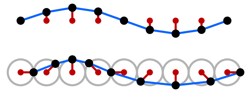
In reality surface points do drift and don't describe perfect circles, but Gerstner waves don't model this. That's fine, because we'll use the original vertex positions as the anchor points.
We can turn our sine wave into a circle by using `P=[[acosf],[asinf]]`, but that would collapse the entire plane into a single circle. Instead, we have to anchor each point on its original X coordinate, so we need `P=[[x+acosf],[asinf]]`.
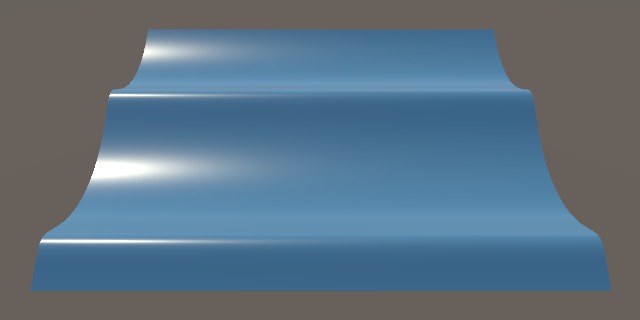
			float k = 2 * UNITY_PI / _Wavelength;
			float f = k * (p.x - _Speed * _Time.y);
			p.x += _Amplitude * cos(f);
			p.y = _Amplitude * sin(f);
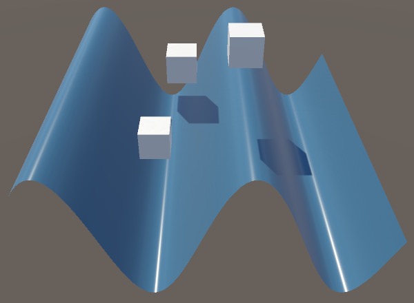
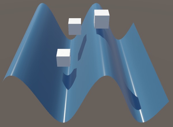
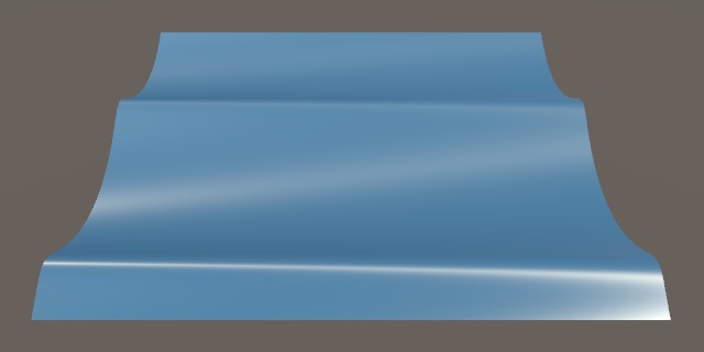
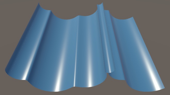
The result is a wave that has sharper crests and flatter troughs than a regular sine wave.
Normal Vectors
Because we changed the surface function, its derivate has also changed. The X component of `T` used to be `x^'=1`, but now it's a bit more complicated. The derivative of the cosine is the negative sine, so we end up with `T=[[1-kasinf],[kacosf]]`.
			float3 tangent = normalize(float3(
				1 - k * _Amplitude * sin(f),
				k * _Amplitude * cos(f),
				0
			));
			float3 normal = float3(-tangent.y, tangent.x, 0);
Preventing Loops
While the resulting waves might look fine, this isn't always the case. For example, reducing the wavelength to 20 while keeping the amplitude at 10 produces weird results.
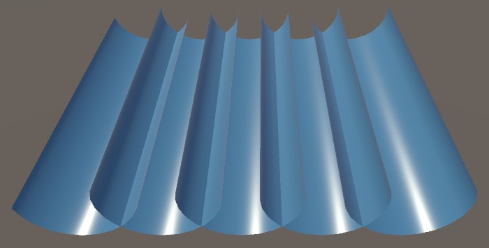
Because the amplitude is so large relative to the wavelength, the orbits of the surface points overshoot and form loops above the surface. If this was real water, then the waves would break and fall apart, but we cannot represent that with Gerstner waves.
We can see why this happens mathematically, by observing that `T_x` can become negative when `ka` is larger than 1. When that happens, the tangent vector ends up pointing backward instead of forward. And when `ka` is 1 then we end up with a tangent vector that points straight up.
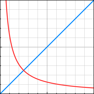
In reality, we don't get intact waves where the angle between both sides of the crests exceed 120°. Gerstner waves don't have this limit, but we don't want to go below 0°, because that's when we get surface loops.
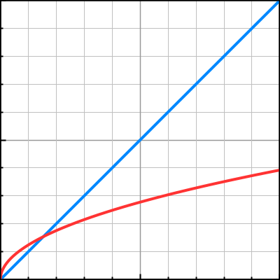
There is a relation between the wavelength and the wave amplitude. We can use `a=e^(kb)/k`, where `b` has to do with surface pressure. The stronger the pressure, the flatter the waves. In case of zero pressure, we end up with `a=1/k`, which produces 0° crests, the sharpest possible before looping. We can just use `a=s/k` instead, where `s` is a measure of steepness, between 0 and 1, which is easier to work with. Then we have `P=[[x+s/kcosf],[s/ksinf]]`, which simplifies our tangent to `T=[[1-ssinf],[scosf]]`.
Shader "Custom/Waves" {
Properties {
…
//_Amplitude ("Amplitude", Float) = 1
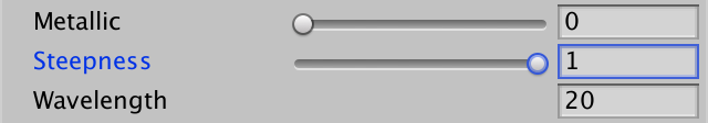
_Steepness ("Steepness", Range(0, 1)) = 0.5
_Wavelength ("Wavelength", Float) = 10
_Speed ("Speed", Float) = 1
}
SubShader {
…
float _Steepness, _Wavelength, _Speed;
void vert(inout appdata_full vertexData) {
float3 p = vertexData.vertex.xyz;
float k = 2 * UNITY_PI / _Wavelength;
float f = k * (p.x - _Speed * _Time.y);
float a = _Steepness / k;
p.x += a * cos(f);
p.y = a * sin(f);
float3 tangent = normalize(float3(
1 - _Steepness * sin(f),
_Steepness * cos(f),
0
));
…
}
…
}
Phase Speed
In reality, waves don't have an arbitrary phase speed. It is related to the wave number, `c=sqrt(g/k)=sqrt((glambda)/(2pi))`, where `g` is the pull of gravity, roughly 9.8 on Earth. This is true for waves in deep water. In shallow water the water depth also plays a role, but we won't cover that here.
While we could just use the correct material properties, it's more convenient to calculate this in the shader.
			float k = 2 * UNITY_PI / _Wavelength;
			float c = sqrt(9.8 / k);
			float f = k * (p.x - c * _Time.y);
Now we can eliminate the speed property.
	Properties {
		…
		_Wavelength ("Wavelength", Float) = 10
		//_Speed ("Speed", Float) = 1
	}
	SubShader {
		…
		float _Steepness, _Wavelength; //, _Speed;
		…
	}
Note that this relationship means that longer waves have a higher phase speed. Also, the stronger the gravity the faster the movement.
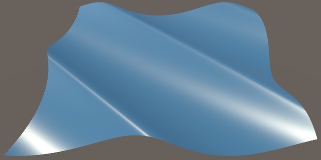
Wave Direction
Up to this point our waves only move in the X dimension. We're now going to remove this restriction. This makes our calculations a bit more complex, as both X and Z are needed to construct the final wave and its tangent vectors.
Direction Vector
To indicate the travel direction of our wave we'll introduce the direction vector `D=[[D_x],[D_z]]`. This is purely an indication of direction, so it's a vector of unit length, `||D||=1`.
Now how much `x` contributes to the wave function is modulated by the X component of `D`. So we get `f=k(D_x x-ct)`. But `z` now also plays a role, in the same way, which leads to `f=k(D_x x+D_z z-ct)`. In other words, we're using the dot product of `D` and the original X and Z coordinates. So we end up with `f=k(D * [[x],[z]]-ct)`.
Add a direction property to our shader and incorporate it into our function. It should be a unit-length vector, but to make it easier to work with we'll normalize it in the shader. Note that all vector properties are 4D, so just ignore the Z and W components.
Shader "Custom/Waves" {
	Properties {
		…
		_Wavelength ("Wavelength", Float) = 10
		_Direction ("Direction (2D)", Vector) = (1,0,0,0)
	}
	SubShader {
		…
		float _Steepness, _Wavelength;
		float2 _Direction;

		void vert(inout appdata_full vertexData) {
			float3 p = vertexData.vertex.xyz;

			float k = 2 * UNITY_PI / _Wavelength;
			float c = sqrt(9.8 / k);
			float2 d = normalize(_Direction);
			float f = k * (dot(d, p.xz) - c * _Time.y);
			…
		}

		…
	}
We also have to adjust the horizontal offsets of `P_x` and `P_z` so they align with the wave direction. So instead of just adding the offset to `x`, we have to add it to `z` as well, in both cases modulated by the appropriate component of `D`. So the final calculation becomes `P=[[x+D_xs/kcosf],[s/ksinf],[z+D_zs/kcosf]]`.
			p.x += d.x * (a * cos(f));
			p.y = a * sin(f);
			p.z += d.y * (a * cos(f));
Normal Vectors
Once again, we have to adjust the calculation of our tangent, but not just for the X dimension. We now also have to calculate the tangent in the Z dimension, the binormal vector `B`.
The partial derivative of `f` in the X dimension is `f_x^'=kD_x`. In the case of `T_x` and `T_y` this simply means that we multiply with `D_x` one more time. Besides that, we also have to add `T_z` because it is no longer zero. The final tangent is `T=[[1-D_x^2ssinf],[D_xscosf],[-D_xD_zssinf]]`
It's the same for the binormal, except that `f_z^'=kD_z`, we multiply with `D_z`, and the roles of the X and Z component are swapped. So `B=[[-D_xD_zssinf],[D_zscosf],[1-D_z^2ssinf]]`.
Now we do need to take the proper cross product to find the normal vector.
			float3 tangent = float3(
				1 - d.x * d.x * (_Steepness * sin(f)),
				d.x * (_Steepness * cos(f)),
				-d.x * d.y * (_Steepness * sin(f))
			);
			float3 binormal = float3(
				-d.x * d.y * (_Steepness * sin(f)),
				d.y * (_Steepness * cos(f)),
				1 - d.y * d.y * (_Steepness * sin(f))
			);
			float3 normal = normalize(cross(binormal, tangent));
Note that `T_z=B_x`. We don't need to optimize for this, because the shader compiler takes care of that, just like the sine and cosine are calculate only once.
Multiple Waves
In reality it is rare to find only a single uniform wave traveling across a water surface. Instead there are many waves, traveling in roughly the same direction. We can improve the realism of our effect by accumulating multiple waves as well.
Combining multiple waves is simply a matter of adding all their offsets. Mathematically, for the X component of `P` we then get `P_x=x+sum_(i=1)^n D_(ix)s_i/k_icosf_i`, and `f_i=k(D_i * [[x],[z]]-ct)`. That's the same formula as before, just with the summation added. The same is true for the other components of `P` and for the tangents.
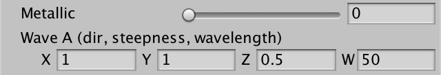
Single Parameter Vector
Each individual wave has its own properties. To make this easier to manage, let's combine all properties of a wave in a single shader property. We can fit them in a single 4D vector, using X and Y for the direction, Z for steepness, and W for the wavelength. Use this trick to define a property for our first wave, wave A.
//_Steepness ("Steepness", Range(0, 1)) = 0.5//_Wavelength ("Wavelength", Float) = 10//_Direction ("Direction (2D)", Vector) = (1,0,0,0)_WaveA ("Wave A (dir, steepness, wavelength)", Vector) = (1,0,0.5,10)
Replace the old variables with the new wave vector.
//float _Steepness, _Wavelength;//float2 _Direction;float4 _WaveA;
Then move the wave code to a new GerstnerWave function. This function has the wave settings as a parameter, followed by the original grid point. Give it input-output parameter for the tangent and binormal as well, so we can accumulate them. It returns its point offset.
Because it accumulates offsets, leave the `x` and `z` parts out of the result. So they should also be omitted from the derivatives, eliminating the 1s. Finally, normalization doesn't happen per individual wave.
		float3 GerstnerWave (
			float4 wave, float3 p, inout float3 tangent, inout float3 binormal
		) {
		    float steepness = wave.z;
		    float wavelength = wave.w;
		    float k = 2 * UNITY_PI / wavelength;
			float c = sqrt(9.8 / k);
			float2 d = normalize(wave.xy);
			float f = k * (dot(d, p.xz) - c * _Time.y);
			float a = steepness / k;

			//p.x += d.x * (a * cos(f));
			//p.y = a * sin(f);
			//p.z += d.y * (a * cos(f));

			tangent += float3(
				-d.x * d.x * (steepness * sin(f)),
				d.x * (steepness * cos(f)),
				-d.x * d.y * (steepness * sin(f))
			);
			binormal += float3(
				-d.x * d.y * (steepness * sin(f)),
				d.y * (steepness * cos(f)),
				-d.y * d.y * (steepness * sin(f))
			);
			return float3(
				d.x * (a * cos(f)),
				a * sin(f),
				d.y * (a * cos(f))
			);
		}
The waves are now relative to a flat plane. So we begin with the original grid point and the default tangent and binormal vectors, then invoke GerstnerWave and add its result to the final point. After that, create the normal vector via a cross product and normalization.
		void vert(inout appdata_full vertexData) {
			float3 gridPoint = vertexData.vertex.xyz;
			float3 tangent = float3(1, 0, 0);
			float3 binormal = float3(0, 0, 1);
			float3 p = gridPoint;
			p += GerstnerWave(_WaveA, gridPoint, tangent, binormal);
			float3 normal = normalize(cross(binormal, tangent));
			vertexData.vertex.xyz = p;
			vertexData.normal = normal;
		}
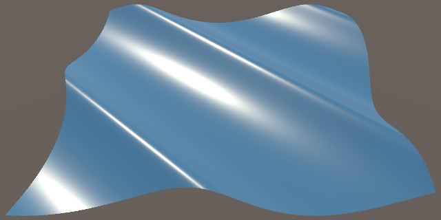
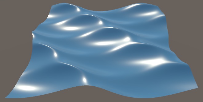
Two Waves
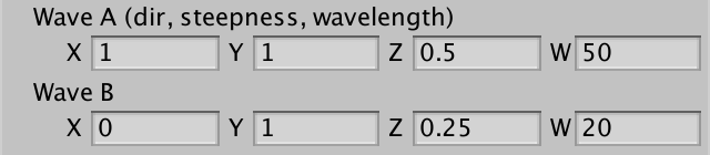
To add support for a second wave, all we have to do is add another wave property and invoke GerstnerWave a second time. I didn't repeat the data description in the label of wave B, because it's the same as wave A.
Shader "Custom/Waves" {
	Properties {
		…
		_WaveA ("Wave A (dir, steepness, wavelength)", Vector) = (1,0,0.5,10)
		_WaveB ("Wave B", Vector) = (0,1,0.25,20)
	}
	SubShader {
		…
		float4 _WaveA, _WaveB;

		…

		void vert(inout appdata_full vertexData) {
			float3 gridPoint = vertexData.vertex.xyz;
			float3 tangent = 0;
			float3 binormal = 0;
			float3 p = gridPoint;
			p += GerstnerWave(_WaveA, gridPoint, tangent, binormal);
			p += GerstnerWave(_WaveB, gridPoint, tangent, binormal);
			float3 normal = normalize(cross(binormal, tangent));
			vertexData.vertex.xyz = p;
			vertexData.normal = normal;
		}

		…
	}
Looping Animations
Now that we have two waves, you can observe that one with a longer wavelength indeed travels faster than a shorter one. But the relationship between phase speed and wavelength is nonlinear, because `c=sqrt(gk)=sqrt((glambda)/(2pi))`. This is relevant when you want to create a looping animation with multiple waves. In the case of two waves, you have to find two wavelengths that produce phase speeds with the relationship `ac_1=bc_2`, where `a` and `b` are integers. You could do this by using even powers of two for wavelengths.
For example, let's use `lambda_1=64=2^6` and `lambda_2=16=2^4`. Then `c_1=sqrt((2^6g)/(2pi))=2^3sqrt(g/(2pi))` and `c_2=sqrt((2^4g)/(2pi))=2^2sqrt(g/(2pi))`. Observe that `sqrt(g/(2pi))` is constant, so we can define it as `q` and use `c_1=2^3q` and `c_2=2^2q`. Thus `c_1=2c_2`, which means that each time the big wave repeats the small wave repeats twice. The loop duration is equal to the period of the large wave, which is `lambda/c=2^6/(2^3q)=2^3/q~~6.41` seconds.
You could also rewrite the math so that you directly control the phase speed and derive the wavelength from that instead.
Looping Waves
Another important observation is that we can get looping waves again. If the sum of a partial derivative exceeds 1, then a loop forms. To prevent looping waves you have to ensure that the sum of the steepness properties of all waves does not exceed 1.
You can enforce this restriction by normalizing the steepness in the shader. This means that if you change the steepness of one wave it affects all other waves. Alternatively, you can divide all steepness values by the number of waves, but that limits the steepness per wave. You could also set no restrictions in the shader, and instead provide feedback and options via the material inspector. For this tutorial, we simply set no restrictions at all.
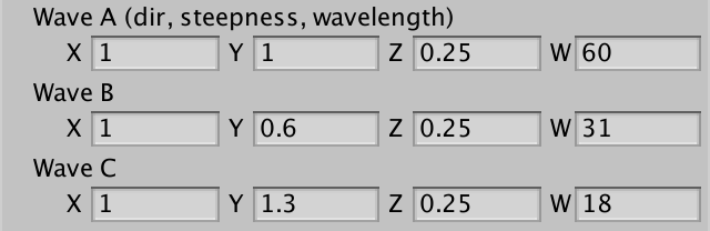
Three Waves
We wrap up by adding support for yet another wave. The more waves we add, the more complex our shader becomes. You can make shader variations based on the amount of waves, but we'll just three as a fixed amount.
Shader "Custom/Waves" {
	Properties {
		…
		_WaveA ("Wave A (dir, steepness, wavelength)", Vector) = (1,0,0.5,10)
		_WaveB ("Wave B", Vector) = (0,1,0.25,20)
		_WaveC ("Wave C", Vector) = (1,1,0.15,10)
	}
	SubShader {
		…
		float4 _WaveA, _WaveB, _WaveC;

		…

		void vert(inout appdata_full vertexData) {
			float3 gridPoint = vertexData.vertex.xyz;
			float3 tangent = 0;
			float3 binormal = 0;
			float3 p = gridPoint;
			p += GerstnerWave(_WaveA, gridPoint, tangent, binormal);
			p += GerstnerWave(_WaveB, gridPoint, tangent, binormal);
			p += GerstnerWave(_WaveC, gridPoint, tangent, binormal);
			float3 normal = normalize(cross(binormal, tangent));
			vertexData.vertex.xyz = p;
			vertexData.normal = normal;
		}

		…
	}
The next tutorial is Looking Through Water.