Creating a Mesh
Vertices and Triangles
- Generate a triangle and a quad via code.
- Define vertex positions, normals, tangents, and texture coordinates.
- Use both the simple and advanced Mesh API.
- Store vertex data in multiple streams or a in single stream.
This is the first tutorial in a series about procedural meshes. It comes after the Pseudorandom Noise series. It introduces multiple ways to create a mesh via code, via the simple and advanced Mesh API.
This tutorial is made with Unity 2020.3.18f1.
Constructing a Triangle
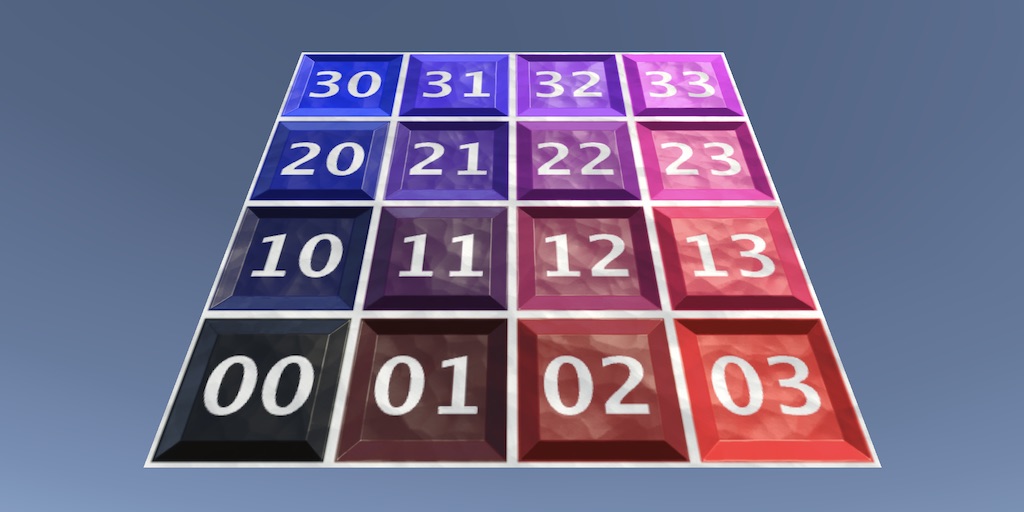
The typical way to show something is to render a mesh, with a specific material. Unity has a few built-in meshes of simple shapes, including a cube and a sphere. Other meshes can be bought, downloaded, or made yourself and then imported into a project. But it is also possible to create a mesh on-demand at runtime via code, which is what this series is about. Such meshes are known as procedural, because they're generated via code using specific algorithms, instead of being modeled by hand.
Start with a new project as described in the Basics series. We'll use types from Mathematics, so import it via the package manager. Although we won't need it in this tutorial yet, I also already include the Burst package as well. Finally, I'll use URP so import Universal RP and create an asset for it and configure Unity to use it.
Simple Procedural Mesh Component
There are two different ways to create a mesh procedurally: the simple and the advanced way. Each has its own API.
We'll use both approaches to generate the same mesh in turn, beginning with the simple Mesh API. This approach has always been part of Unity. Create a component type for it, naming it SimpleProceduralMesh.
using UnityEngine;

public class SimpleProceduralMesh : MonoBehaviour { }
We'll use this custom component type to generate our mesh when we enter play mode. To draw the mesh we need a game object that also has a MeshFilter and a MeshRenderer component. We can enforce that these components are added to the same game object that we add our own component to, by giving it the RequireComponent attribute with both component types as arguments. To indicate that we refer to the types themselves we have to pass each to the typeof operator, as if it were a method invocation.
[RequireComponent(typeof(MeshFilter), typeof(MeshRenderer))]
public class SimpleProceduralMesh : MonoBehaviour { }
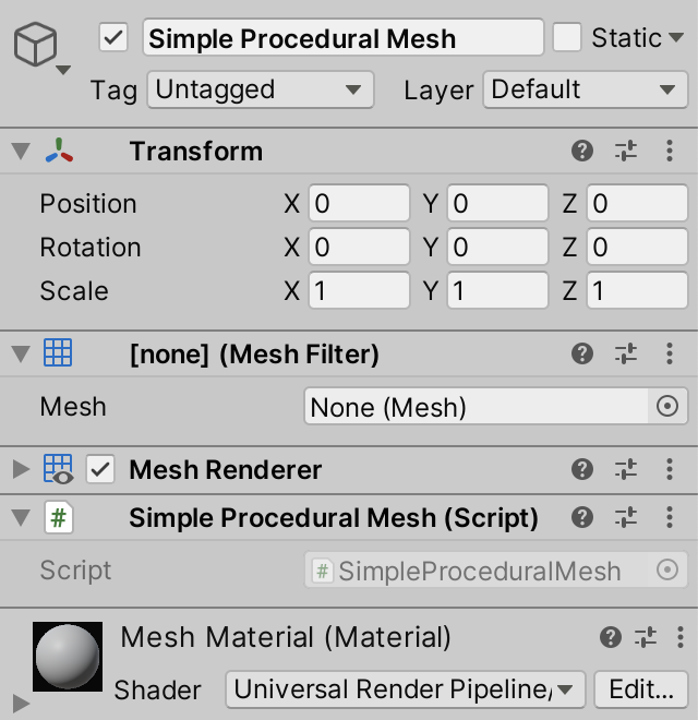
Create a new empty game object and attach our SimpleProceduralMesh to it. This will also automatically give it a MeshFilter and a MeshRenderer component. Then create a new default URP material and assign it to our game object, because the default MeshRenderer component doesn't have a material set. The MeshFilter component also doesn't have a mesh yet, but that is correct, because we'll give it one while in play mode.
We generate the mesh in the OnEnable method. This is done by creating a new Mesh object. Also name it Procedural Mesh by settings its name property.
public class SimpleProceduralMesh : MonoBehaviour {

	void OnEnable () {
		var mesh = new Mesh {
			name = "Procedural Mesh"
		};
	}
}
Then we assign it to the mesh property of our MeshFilter component, which we can access by invoking the generic GetComponent method on our component, specifically for MeshFilter.
		var mesh = new Mesh {
			name = "Procedural Mesh"
		};

		GetComponent<MeshFilter>().mesh = mesh;
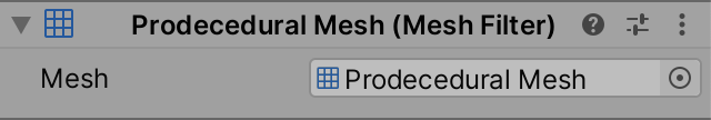
When we enter play mode now a reference to our mesh will appear in the inspector of MeshFilter, even though nothing gets drawn. We can access the inspector of our mesh via double-clicking on its reference, or via the Properties... option of the context menu that we can open for it.

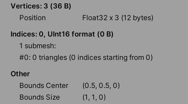
This tells us the current state of our mesh. It doesn't have any vertices nor indices, it has one submesh with zero triangles, and its bounds are set to zero. So there is nothing to draw yet.
Adding Vertices
A mesh contains triangles, which are the simplest surfaces that can be described in 3D. Each triangle has three corners. These are the vertices of the mesh, which we will define first.
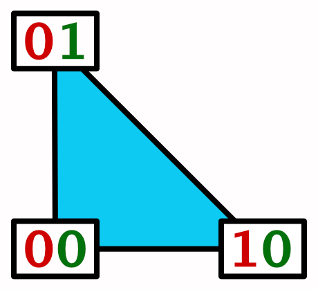
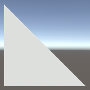
At its most simplest a vertex is nothing more than a position in 3D space, described with a Vector3 value. We'll create vertices for a single triangle, using the default zero, right, and up vectors. This defines an isosceles right triangle that lies on the XY plane, with its 90° corner at the origin and the other corners a single unit away in a different dimension each.
There are multiple ways in which we could set the vertices via the simple Mesh API, but the simplest is to create a Vector3 array with the desired vertices and assign it to the vertices property of our mesh.
		var mesh = new Mesh {
			name = "Procedural Mesh"
		};

		mesh.vertices = new Vector3[] {
			Vector3.zero, Vector3.right, Vector3.up
		};

		GetComponent<MeshFilter>().mesh = mesh;
Entering play mode now and then inspecting our mesh shows us that it has three vertices. Each vertex defines a position, which consists of three 32-bit float values, so that's three times four bytes, thus twelve bytes per vertex, for a total of 36 bytes.
There are no triangles yet, but the mesh has already automatically derived its bounds from the vertices that we gave it.
Defining the Triangle
Vertices alone are not enough. We also have to describe how the triangles of the mesh are to be drawn, even for a trivial mesh that only has a single triangle. We'll do this by assigning an int array with triangle indices to the triangles property, after setting the vertices. These indices refer to the indices of the vertex positions. The most straightforward thing to do would be to list the three indices in order: 0, 1, and 2.
		mesh.vertices = new Vector3[] {
			Vector3.zero, Vector3.right, Vector3.up
		};

		mesh.triangles = new int[] {
			0, 1, 2
		};
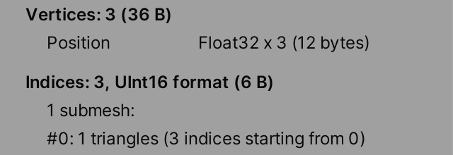
Now our mesh tells us that is has a single triangle, defined by three vertex indices. The indices always start from index zero in the triangle array because there is only a single submesh. The indices take up only 6 bytes in total instead of 12 because they are stored as UInt16, which matches the 16-bit ushort C# type, which defines an unsigned integer with only two bytes instead of four.
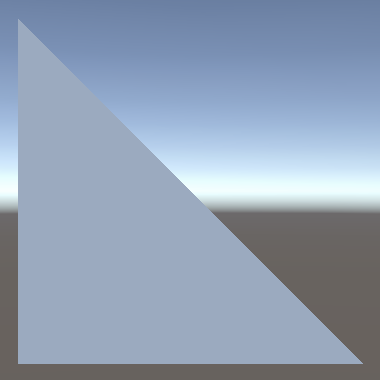
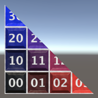
A triangle has also finally shown up in the game and scene windows, but it isn't visible from all view directions. By default triangles are only visible when looking at their front face, not their back face. Which side you're looking at is determined by the winding order of the vertices. If you trace the edges of the triangle, going through its vertices in the order indicated by the indices, you end up going either clockwise or counterclockwise, visually. The clockwise side is the front face, so that is the visible side.
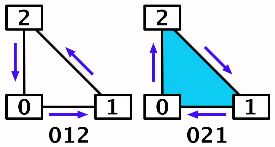
This means that we'll only see the triangle when looking in the negative Z direction. We can turn this around by swapping the order of the second and third vertex indices. Then we can see the triangle when looking in the positive Z direction.
		mesh.triangles = new int[] {
			0, 2, 1
		};
Normal Vectors
Currently the lighting of our triangle is incorrect. It behaves as if it gets lit from the opposite side. This happens because we haven't defined the normal vectors yet, which are used by shaders to calculate lighting.
A normal vector is a unit-length vector that describes the local up direction if you were standing on a surface. So these vectors point straight away from the surface. Thus the normal vector for our triangle surface should be Vector3.back, pointing straight down the negative Z axis in the local space of our mesh. But if no normal vectors are provided Unity uses the forward vector by default, hence our triangle appears to be lit from the wrong side.
Although it only really makes sense to define a normal vector for a surface, a mesh defines normal vectors per vertex. The final surface normal used for shading is found by interpolating the vertex normal across the surface of the triangle. By using different normal vectors the illusion of surface curvature can be added to flat triangles. This makes it possible to give meshes the appearance of being smooth while in reality they are faceted.
We can add normal vectors to vertices by assigning a Vector3 array to the normals property of our mesh, after setting the vertex positions. Unity checks whether the arrays have the same length and will fail and complain if we supply the wrong amount of normal vectors.
		mesh.vertices = new Vector3[] {
			Vector3.zero, Vector3.right, Vector3.up
		};

		mesh.normals = new Vector3[] {
			Vector3.back, Vector3.back, Vector3.back
		};
As a consequence of adding normal vectors the size of our vertex data has doubled to 24 bytes per vertex and 72 bytes in total.

Texturing
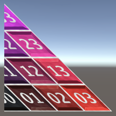
Surface details can be added to the mesh by applying a texture to it. The simplest texture is an image that is used to colorize the surface. In the case of URP this is known as a base map. Here is such a texture, which makes it easy to see how the texture is applied to the triangle.
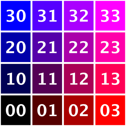
Download the image, then import it into your project, either by placing it into the project's Assets folder or via dragging and dropping the file onto the project window. Then assign it to the Base Map property of the material.

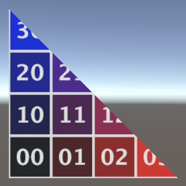
Initially this appears to make no difference, because we haven't defined any texture coordinates yet. They're zero by default, which means that the bottom left corner of the texture is used for the entire triangle, which is white.
As the texture is a 2D image and the triangle surface is also 2D, the texture coordinates are Vector2 values. They specify where to sample the texture at each vertex and they will be interpolated across the triangle surface. They're normalized coordinates, so the 0–1 inclusive range covers the entire texture, per dimension.
In Unity the origin is at the bottom left corner of textures, so the most obvious texture mapping without distortion matches the vertex positions. We add them to the mesh by assigning an array to its uv property. Texture coordinates are often described as UV coordinates because they're two-dimensional coordinates in texture space, named U and V instead of X and Y.
		mesh.vertices = new Vector3[] {
			Vector3.zero, Vector3.right, Vector3.up
		};

		mesh.normals = new Vector3[] {
			Vector3.back, Vector3.back, Vector3.back
		};

		mesh.uv = new Vector2[] {
			Vector2.zero, Vector2.right, Vector2.up
		};
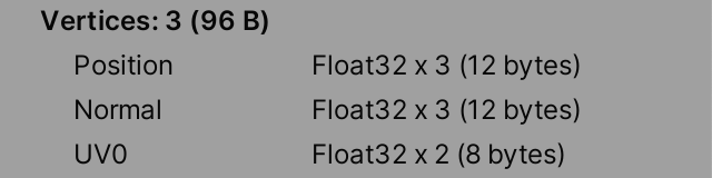
The mesh inspector will list the texture coordinates as UV0 and shows that they add 8 bytes to the vertex size.
You could also map the texture in a different way, for example by using Vector2.one for the third vertex. This will distort the image, shearing it.
Normal Mapping
Another common way to add surface details is via normal mapping. This is usually done via a normal map texture, which is an image that contains surface normal vectors. Here is such a texture, which describes a strong checkerboard pattern of alternating raised and lowered bevels, plus some subtle unevenness for variation.
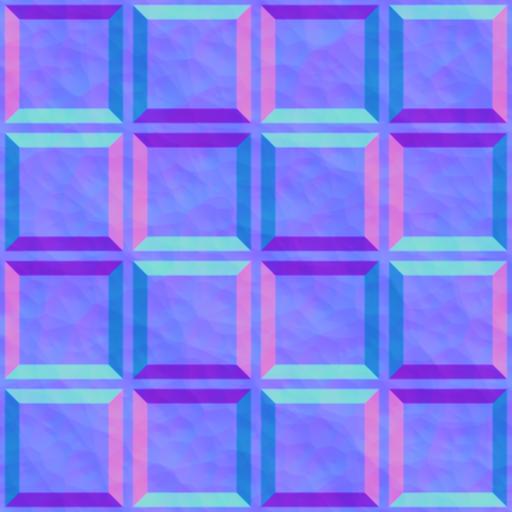
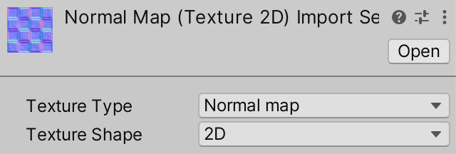
After importing the image, set its Texture Type to Normal map, otherwise it won't be properly interpreted by Unity.
Then use it as the Normal Map of the material.

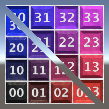
Just like the vertex normal vectors, the normal map is used to adjust the surface normal vector, adding the illusion of surface variation that affects lighting, even through the triangle is still flat.
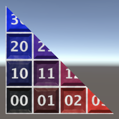
Although this already appears to work, the result is currently incorrect. What appears higher should appear lower instead, and vice versa. This happens because the vectors from the normal map exist in texture space and have to be converted to world space to affect lighting. This requires a transformation matrix, which defines a 3D space relative to the surface, known as tangent space. It consists of a right, an up, and a forward axis.
The up axis should point away from the surface, for which the vertex normal vectors are used. Besides that we also need a right and a forward axis. The right axis should point in whatever direction we consider right, in our case simply Vector3.right. It is also known as the tangent axis or vector, because it must always be tangent to the surface curvature. We define these per vertex by assigning vectors to the tangents property of the mesh. The shader can construct the third axis itself by calculating the vector orthogonal to the normal and tangent. However, it could this in two different ways, producing a vector pointing either forward or backward. That's why the tangent vectors have to be Vector4 values: their fourth component should be either 1 or −1, to control the direction of the third axis.
The default tangent vectors point to the right and have their fourth component set to 1. Due to how Unity's shaders construct tangent space this is incorrect, we have to use −1 instead.
		mesh.normals = new Vector3[] {
			Vector3.back, Vector3.back, Vector3.back
		};

		mesh.tangents = new Vector4[] {
			new Vector4(1f, 0f, 0f, -1f),
			new Vector4(1f, 0f, 0f, -1f),
			new Vector4(1f, 0f, 0f, -1f)
		};
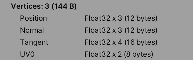
As tangent vectors have four components our vertex size has grown by 16 bytes, to a final size of 48 bytes. That's a total of 144 bytes for our three vertices.
Constructing a Quad
Meshes can contain more that a single triangle. To demonstrate this we'll turn our mesh into a quad by adding a second triangle to it.
A Second Triangle
We can create a quad by taking two right isosceles triangles and putting them together with their hypotenuses touching. We keep our existing triangle and add a second one with its right corner at one unit from the origin in both the X and Y dimensions. We'll use the vertex order right, up, one. But to make it clear that we have two distinct triangles we'll initially slightly offset and scale up the new triangle, by increasing its coordinates from 1 to 1.1. Add the required positions to the vertices array.
		mesh.vertices = new Vector3[] {
			Vector3.zero, Vector3.right, Vector3.up,
			new Vector3(1.1f, 0f), new Vector3(0f, 1.1f), new Vector3(1.1f, 1.1f)
		};
Also increase the normals and tangents arrays so they have the same size, simply filling them with the same values.
		mesh.normals = new Vector3[] {
			Vector3.back, Vector3.back, Vector3.back,
			Vector3.back, Vector3.back, Vector3.back
		};

		mesh.tangents = new Vector4[] {
			new Vector4(1f, 0f, 0f, -1f),
			new Vector4(1f, 0f, 0f, -1f),
			new Vector4(1f, 0f, 0f, -1f),
			new Vector4(1f, 0f, 0f, -1f),
			new Vector4(1f, 0f, 0f, -1f),
			new Vector4(1f, 0f, 0f, -1f)
		};
To keep our texture undistorted and matching we have to use appropriate texture coordinates for the new vertices.
		mesh.uv = new Vector2[] {
			Vector2.zero, Vector2.right, Vector2.up,
			Vector2.right, Vector2.up, Vector2.one
		};
Finally, add its indices to the triangles array. Due to the way we defined the new vertices we can list them in sequence.
		mesh.triangles = new int[] {
			0, 2, 1, 3, 4, 5
		};
Reusing Vertices
We don't need to define separate vertices per triangle, it is possible for multiple triangles to use the same vertex. We can't do this while the triangles are separate, but to finish the quad we'll push them together, which means that we can reuse the right and up vertices of the first triangle for the second one. Thus we can reduce our vertex array to four positions: zero, right, up, and one on the XY plane.
		mesh.vertices = new Vector3[] {
			Vector3.zero, Vector3.right, Vector3.up, new Vector3(1f, 1f)
			//new Vector3(1.1f, 0f), new Vector3(0f, 1.1f), new Vector3(1.1f, 1.1f)
		};
Likewise, eliminate the redundant data from the other arrays.
		mesh.normals = new Vector3[] {
			Vector3.back, Vector3.back, Vector3.back, Vector3.back
			//Vector3.back, Vector3.back, Vector3.back,
		};

		mesh.tangents = new Vector4[] {
			new Vector4(1f, 0f, 0f, -1f),
			new Vector4(1f, 0f, 0f, -1f),
			new Vector4(1f, 0f, 0f, -1f),
			//new Vector4(1f, 0f, 0f, -1f),
			//new Vector4(1f, 0f, 0f, -1f),
			new Vector4(1f, 0f, 0f, -1f)
		};

		mesh.uv = new Vector2[] {
			Vector2.zero, Vector2.right, Vector2.up, Vector2.one
			//Vector2.right, Vector2.up, Vector2.one
		};
The index list for the second triangle now becomes 1, 2, 3.
		mesh.triangles = new int[] {
			0, 2, 1, 1, 2, 3
		};
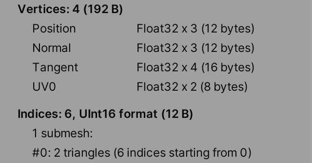
We can verify via the inspector that the mesh has four vertices and two triangles.
Advanced Mesh API
Unity 2019 introduced an alternative advanced Mesh API, which allows more efficient generation of meshes, making it possible to skip intermediate steps and automatic verifications. Unity 2020 expanded on this API to make it work well with jobs and Burst. We'll use this last approach, even though we won't use separate jobs in this tutorial yet.
Multi-Stream Approach
When we assign data to a mesh via the simple API Unity has to copy and convert everything to the mesh's native memory at some point. The advanced API allows us to work directly in the native memory format of the mesh, skipping conversion. This means that we must be aware of how the data of the mesh is laid out.
The memory of the mesh is split into regions. The two regions we need to know about are the vertex region and the index region. The vertex region consists of one or more data streams, which are sequential blocks of vertex data of the same format. Unity supports up to four different vertex data streams per mesh.
As we have vertex positions, normals, tangents, and texture coordinates we could store each in a separate stream. Let's call this the multi-stream approach.

Create a new AdvancedMultiStreamProceduralMesh component type that—like before with SimpleProceduralMesh—initially only creates an empty mesh and assigns it to the MeshFilter.
using UnityEngine;

[RequireComponent(typeof(MeshFilter), typeof(MeshRenderer))]
public class AdvancedMultiStreamProceduralMesh : MonoBehaviour {

	void OnEnable () {
		var mesh = new Mesh {
			name = "Procedural Mesh"
		};

		GetComponent<MeshFilter>().mesh = mesh;
	}
}
Then replace the simple component of our game object with the new advanced one, or alternatively adjust a duplicate and disable the simple version, so you can compare them later.
Mesh Data
To write into native mesh data we have to first allocate it. We do this by invoking the static Mesh.AllocateWritableMeshData method. To facilitate generating meshes in batches this method returns a Mesh.MeshDataArray struct that acts like an array of native mesh data, available for writing. We have to tell it how many meshes we want to generate, which is just one. Do this before creating the Mesh object and keep track of the array via a variable.
		Mesh.MeshDataArray meshDataArray = Mesh.AllocateWritableMeshData(1);

		var mesh = new Mesh {
			name = "Procedural Mesh"
		};
Leaving the data empty for now, we finish by invoking Mesh.ApplyAndDisposeWritableMeshData, with the array and the mesh it applies to as arguments. We can directly apply the array to the mesh because it only has a single element. Afterwards we can no longer access the mesh data, unless we retrieve it again via Mesh.AcquireReadOnlyMeshData.
		var mesh = new Mesh {
			name = "Procedural Mesh"
		};
		Mesh.ApplyAndDisposeWritableMeshData(meshDataArray, mesh);
		GetComponent<MeshFilter>().mesh = mesh;
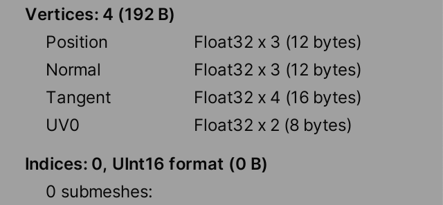
If we enter play mode now the mesh's inspector will show that it is completely empty.
To fill the mesh data we have to retrieve the single element from the array, keeping track of it via a variable. Its type is Mesh.MeshData.
		Mesh.MeshDataArray meshDataArray = Mesh.AllocateWritableMeshData(1);
		Mesh.MeshData meshData = meshDataArray[0];
Vertex Attributes
At this point the format of the mesh data is still undefined, we have to define it ourselves. For this we need to use types from the Unity.Collections and UnityEngine.Rendering namespaces.
using Unity.Collections;
using UnityEngine;
using UnityEngine.Rendering;
Each vertex of our mesh has four attributes: a position, a normal, a tangent, and a set of texture coordinates. We'll describe these by allocating a temporary native array with VertexAttributeDescriptor elements. I'll store the count values in variables to make it clear what the numbers represent.
		int vertexAttributeCount = 4;

		Mesh.MeshDataArray meshDataArray = Mesh.AllocateWritableMeshData(1);
		Mesh.MeshData meshData = meshDataArray[0];

		var vertexAttributes = new NativeArray<VertexAttributeDescriptor>(
			vertexAttributeCount, Allocator.Temp
		);
The vertex streams of the mesh are then allocated by invoking SetVertexBufferParams on the mesh data, with the vertex count and the attribute definitions as arguments. After that we no longer need the attribute definition, so we dispose of it.
		int vertexAttributeCount = 4;
		int vertexCount = 4;

		Mesh.MeshDataArray meshDataArray = Mesh.AllocateWritableMeshData(1);
		Mesh.MeshData meshData = meshDataArray[0];

		var vertexAttributes = new NativeArray<VertexAttributeDescriptor>(
			vertexAttributeCount, Allocator.Temp
		);
		meshData.SetVertexBufferParams(vertexCount, vertexAttributes);
		vertexAttributes.Dispose();
Before setting the vertex buffer parameters we have to describe the four attributes, setting each vertex attribute to a new VertexAttributeDescriptor struct value. We begin with the position. The constructor of VertexAttributeDescriptor has four optional parameters, to describe the attribute type, format, dimensionality, and the index of the stream that contains it. The default values are correct for our position, but we have to provide at least a single argument otherwise we end up using the constructor without arguments, which would be invalid. So let's explicitly set the dimension argument to 3, which indicates that it consists of three component values.
		var vertexAttributes = new NativeArray<VertexAttributeDescriptor>(
			vertexAttributeCount, Allocator.Temp, NativeArrayOptions.UninitializedMemory
		);
		vertexAttributes[0] = new VertexAttributeDescriptor(dimension: 3);
		meshData.SetVertexBufferParams(vertexCount, vertexAttributes);
We follow this by setting the attributes for normals, tangents, and texture coordinates. The first argument for each should be VertexAttribute.Normal, VertexAttribute.Tangent, and VertexAttribute.TexCoord0. Also set their dimensionality appropriately and give them successive stream indices.
		vertexAttributes[0] = new VertexAttributeDescriptor(dimension: 3);
		vertexAttributes[1] = new VertexAttributeDescriptor(
			VertexAttribute.Normal, dimension: 3, stream: 1
		);
		vertexAttributes[2] = new VertexAttributeDescriptor(
			VertexAttribute.Tangent, dimension: 4, stream: 2
		);
		vertexAttributes[3] = new VertexAttributeDescriptor(
			VertexAttribute.TexCoord0, dimension: 2, stream: 3
		);
The mesh inspector will now show the same vertex data layout and size as for our simple mesh example. It doesn't reveal how this data is split into streams.
We can optimize our usage of the native array a bit more by skipping its memory initialization step. By default Unity fills the allocated memory block with zeros, to guard against weird values. We can skip this step by passing NativeArrayOptions.UninitializedMemory as a third argument to the NativeArray constructor.
		var vertexAttributes = new NativeArray<VertexAttributeDescriptor>(
			vertexAttributeCount, Allocator.Temp, NativeArrayOptions.UninitializedMemory
		);
This means that the contents of the array are arbitrary and can be invalid, but we overwrite it all so that doesn't matter.
Setting Vertices
Although we won't use a job in this tutorial, at this point we'll switch to using Mathematics.
using Unity.Mathematics;

using static Unity.Mathematics.math;
After invoking SetVertexBufferParams we can retrieve native arrays for the vertex streams by invoking GetVertexData. The native array that it returns is in reality a pointer to the relevant section of the mesh data. So it acts like a proxy and there is no separate array. This would allow a job to directly write to the mesh data, skipping an intermediate copy step from native array to mesh data.
GetVertexData is a generic method that returns a native array for the first stream by default, which contains the positions. So the array's element type is float3. Use it to set the positions, this time with float3 instead of Vector3.
		meshData.SetVertexBufferParams(vertexCount, vertexAttributes);
		vertexAttributes.Dispose();

		NativeArray<float3> positions = meshData.GetVertexData<float3>();
		positions[0] = 0f;
		positions[1] = right();
		positions[2] = up();
		positions[3] = float3€(1f, 1f, 0f);
Do the same for the rest of the vertex data, passing the appropriate stream index as an argument to GetVertexData.
		NativeArray<float3> positions = meshData.GetVertexData<float3>();
		positions[0] = 0f;
		positions[1] = right();
		positions[2] = up();
		positions[3] = float3€(1f, 1f, 0f);

		NativeArray<float3> normals = meshData.GetVertexData<float3>(1);
		normals[0] = normals[1] = normals[2] = normals[3] = back();

		NativeArray<float4> tangents = meshData.GetVertexData<float4>(2);
		tangents[0] = tangents[1] = tangents[2] = tangents[3] = float4€(1f, 0f, 0f, -1f);

		NativeArray<float2> texCoords = meshData.GetVertexData<float2>(3);
		texCoords[0] = 0f;
		texCoords[1] = float2€(1f, 0f);
		texCoords[2] = float2€(0f, 1f);
		texCoords[3] = 1f;
Settings Triangles
We also have to reserve space for the triangle indices, which is done by invoking SetIndexBufferParams. Its first argument is the triangle index count. It also has a second argument, which describes the index format. Let's initially use IndexFormat.UInt32, which matches the uint type. We do this after setting the vertex data.
		int vertexAttributeCount = 4;
		int vertexCount = 4;
		int triangleIndexCount = 6;

		…

		meshData.SetIndexBufferParams(triangleIndexCount, IndexFormat.UInt32);

		var mesh = new Mesh {
			name = "Procedural Mesh"
		};
A native array for the triangle indices can be retrieved via the generic GetIndexData method. Use it to set the six indices.
		meshData.SetIndexBufferParams(triangleIndexCount, IndexFormat.UInt32);
		NativeArray<uint> triangleIndices = meshData.GetIndexData<uint>();
		triangleIndices[0] = 0;
		triangleIndices[1] = 2;
		triangleIndices[2] = 1;
		triangleIndices[3] = 1;
		triangleIndices[4] = 2;
		triangleIndices[5] = 3;
Our mesh now has indices, but they require twice as much space as our simple mesh needs. That's because we're using the 32-bit unsigned integer type.

This format allows access to an enormous amount of vertices, but Unity uses the smaller 16-bit type by default, which halves the size of the index buffer. This constrains the amount of accessible vertices to 65.535. As we only have six vertices we can suffice with IndexFormat.UInt16, which matches the ushort type.
		meshData.SetIndexBufferParams(triangleIndexCount, IndexFormat.UInt16);
		NativeArray<ushort> triangleIndices = meshData.GetIndexData<ushort>();

Setting the Submesh
The final step is to define the submeshes of the mesh. We do this after setting the indices, by setting the subMeshCount property to 1.
		meshData.subMeshCount = 1;

		var mesh = new Mesh {
			name = "Procedural Mesh"
		};

We also have to specify what part of the index buffer the submesh should use. This is done by invoking SetSubMesh with the submesh index and a SubMeshDescriptor value. The SubMeshDescriptor constructor has two arguments, for the index start and index count. In our case it should cover all indices.
		meshData.subMeshCount = 1;
		meshData.SetSubMesh(0, new SubMeshDescriptor(0, triangleIndexCount));
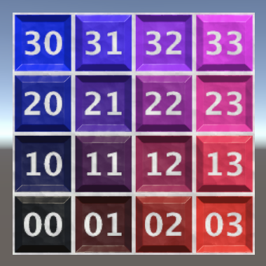
Now we finally see our quad again.

Mesh and Submesh Bounds
When we create a mesh this way Unity doesn't automatically calculate its bounds. However, Unity does calculate the bounds of a submesh, which are needed in some cases. This requires checking all vertices of the submesh. We can avoid all that work be providing the correct bounds ourselves, by setting the bounds property of the submesh descriptor that we pass to SetSubMesh. We should also set its vertexCount property.
		var bounds = new Bounds(new Vector3(0.5f, 0.5f), new Vector3(1f, 1f));

		meshData.subMeshCount = 1;
		meshData.SetSubMesh(0, new SubMeshDescriptor(0, triangleIndexCount) {
			bounds = bounds,
			vertexCount = vertexCount
		});
And we have to explicitly instruct Unity to not calculate these values itself, by passing MeshUpdateFlags.DontRecalculateBounds as a third argument to SetSubMesh.
		meshData.SetSubMesh(0, new SubMeshDescriptor(0, triangleIndexCount) {
			bounds = bounds,
			vertexCount = vertexCount
		}, MeshUpdateFlags.DontRecalculateBounds);
We can use the same bounds for the entire mesh, by assigning to its bounds property as well.
		var mesh = new Mesh {
			bounds = bounds,
			name = "Procedural Mesh"
		};
Reducing Vertex Size
Ideally the vertex data is kept as small as possible, both to reduce memory pressure and also to improve GPU caching. The default format used for vertex attributes is VertexAttributeFormat.Float32, which matches the float type. Because our mesh is so simple we don't need this much precision. Let's reduce the tangent and texture coordinates format to half precision, by passing VertexAttributeFormat.Float16 as a new second argument. The other two arguments then no longer need to be named.
		vertexAttributes[2] = new VertexAttributeDescriptor(
			VertexAttribute.Tangent, VertexAttributeFormat.Float16, 4, 2
		);
		vertexAttributes[3] = new VertexAttributeDescriptor(
			VertexAttribute.TexCoord0, VertexAttributeFormat.Float16, 2, 3
		);
We also have to adjust our code that sets these values so it uses the half type. This isn't a native C# type, which means that there isn't support for mathematical operations for this type. Instead we have to convert the final values from float to half, via the half€ method.
		half h0 = half€(0f), h1 = half€(1f);

		NativeArray<half4> tangents = meshData.GetVertexData<half4>(2);
		tangents[0] = tangents[1] = tangents[2] = tangents[3] =
			half4€(h1, h0, h0, half€(-1f));

		NativeArray<half2> texCoords = meshData.GetVertexData<half2>(3);
		texCoords[0] = h0;
		texCoords[1] = half2€(h1, h0);
		texCoords[2] = half2€(h0, h1);
		texCoords[3] = h1;
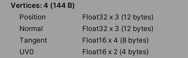
Reducing the tangents and texture coordinates to 16-bit values drops our vertex size by 12 bytes to a total of 36, a reduction of 25%.
There are multiple data formats available, but there is a size restriction: each attribute's total size must be a multiple of four bytes. If we were to switch the position or normal to 16-bit values then their total size would be three times two bytes, so six bytes each, which isn't a multiple of four. So we cannot simply use VertexAttributeFormat.Float16 for the position and normal attributes, unless we increased their dimensionality to 4. That would introduce a useless component but would reduce their size from 12 to 8 bytes. However, we won't do this because usually 32-bit precision is needed for these attributes. Also, the Unity editor expects 3D position vectors when it checks whether you drag-select a mesh in the scene window. If this is not the case then this action will produce a stream of errors and an incorrect selection.
There are also other data formats, but they're not as trivial to support as converting from float to half, so I don't include them in this tutorial.
Single-Stream Approach
It isn't required to put each attribute in a single stream, otherwise it would only be possible to support up to four vertex attributes. The other extreme is to put all attributes in a single stream. In that case the attributes are grouped per vertex, so the data is mixed.

Although we could define the attributes in any order, Unity requires a fixed attribute order per stream: position, normal, tangent, color, texture coordinate sets from 0 up to 7, blend weights, and blend indices.
We'll demonstrate the single-stream approach by introducing an AdvancedSingleStreamProceduralMesh component type that's initially a copy of AdvancedMultiStreamProceduralMesh with only its name changed. Adjust the scene like we did earlier so we can see the result of this new approach.
public class AdvancedSingleStreamProceduralMesh : MonoBehaviour {

	…
}
To store the vertex data we have to define a struct type for it, which we'll name Vertex. Do this inside AdvancedSingleStreamProceduralMesh as we won't use it anywhere else. Give it fields for the required data matching our multi-stream approach, with the correct types and in the correct order.
public class AdvancedSingleStreamProceduralMesh : MonoBehaviour {

	struct Vertex {
		public float3 position, normal;
		public half4 tangent;
		public half2 texCoord0;
	}

	…
}
Because this data gets copied directly to the mesh and to GPU memory without modification it is essential that this data structure is used exactly as we describe it. This isn't guaranteed by default, because the C# compiler might rearrange things in an effort to optimize our code. We can enforce the exact order by attaching the StructLayout attribute to it with the LayoutKind.Sequential argument. Both are from the System.Runtime.InteropServices namespace.
using System.Runtime.InteropServices;
…

[RequireComponent(typeof(MeshFilter), typeof(MeshRenderer))]
public class AdvancedSingleStreamProceduralMesh : MonoBehaviour {

	[StructLayout(LayoutKind.Sequential)]
	struct Vertex { … }

	…
}
To put all attributes in the first stream we can simply remove the stream argument from all VertexAttributeDescriptor constructor invocations.
vertexAttributes[0] = new VertexAttributeDescriptor(dimension: 3); vertexAttributes[1] = new VertexAttributeDescriptor( VertexAttribute.Normal, dimension: 3//, stream: 1); vertexAttributes[2] = new VertexAttributeDescriptor( VertexAttribute.Tangent, VertexAttributeFormat.Float16, 4//, 2); vertexAttributes[3] = new VertexAttributeDescriptor( VertexAttribute.TexCoord0, VertexAttributeFormat.Float16, 2//, 3);
Next, remove the code that sets the separate streams. Retrieve the native array for the single Vertex stream instead.
vertexAttributes.Dispose();//NativeArray<float3> positions = meshData.GetVertexData<float3>();//…//NativeArray<float3> normals = meshData.GetVertexData<float3>(1);//…//NativeArray<half4> tangents = meshData.GetVertexData<half4>(2);//…//NativeArray<half2> texCoords = meshData.GetVertexData<half2>(3);//…NativeArray<Vertex> vertices = meshData.GetVertexData<Vertex>(); meshData.SetIndexBufferParams(triangleIndexCount, IndexFormat.UInt16); NativeArray<ushort> triangleIndices = meshData.GetIndexData<ushort>();
Finally, set the same vertices again, but now by assigning complete vertices to the single array. As they all have the same normal and tangent we can set those once, only changing the position and texture coordinates per vertex.
		vertexAttributes.Dispose();

		NativeArray<Vertex> vertices = meshData.GetVertexData<Vertex>();

		half h0 = half€(0f), h1 = half€(1f);

		var vertex = new Vertex {
			normal = back(),
			tangent = half4€(h1, h0, h0, half€(-1f))
		};

		vertex.position = 0f;
		vertex.texCoord0 = h0;
		vertices[0] = vertex;

		vertex.position = right();
		vertex.texCoord0 = half2€(h1, h0);
		vertices[1] = vertex;

		vertex.position = up();
		vertex.texCoord0 = half2€(h0, h1);
		vertices[2] = vertex;

		vertex.position = float3€(1f, 1f, 0f);
		vertex.texCoord0 = h1;
		vertices[3] = vertex;

		meshData.SetIndexBufferParams(triangleIndexCount, IndexFormat.UInt16);
The result appears exactly the same as the multi-stream approach—even the mesh inspector shows no difference—but the data layout is different.
The next tutorial is Square Grid.