Icosphere
From Octahedron to Icosahedron
- Create a seamless octasphere.
- Convert from octahedron to icosahedron.
- Make a geodesic icosphere variant.
This is the tenth tutorial in a series about procedural meshes. This time we take our octasphere as a starting point and transform it into an icosphere.
This tutorial is made with Unity 2020.3.35f1.
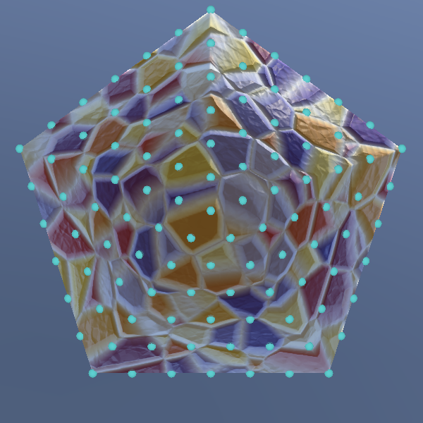
Seamless Octasphere
The final shape that we'll use to generate a sphere is the icosahedron. It has twenty sides so should provide the most even vertex distribution of all the options. The resulting shape is typically known as an icosphere. Like the cube sphere it doesn't have a straight vertical seam going from pole to pole, so it will not support lat/lon texturing and thus only needs to have vertex position data.
Icosphere Type
An icosahedron consists of equilateral triangles, just like an octahedron. Their construction is also similar, so we'll construct the icosphere by adjusting the octasphere, duplicating Octasphere and renaming it to Icosphere.
public struct Icosphere : IMeshGenerator { … }
Add an option for it to ProceduralMesh, with PositionStream so it only generates positions.
	static MeshJobScheduleDelegate[] jobs = {
		…
		MeshJob<SharedCubeSphere, PositionStream>.ScheduleParallel,
		MeshJob<Icosphere, PositionStream>.ScheduleParallel,
		…
	};

	public enum MeshType {
		SquareGrid€, SharedSquareGrid€, SharedTriangleGrid€,
		FlatHexagonGrid€, PointyHexagonGrid€, CubeSphere€, SharedCubeSphere€,
		Icosphere€, Octasphere€, GeoOctasphere€, UVSphere€
	};
No More Seam
Because the icosphere will not contain texture coordinates it doesn't not need a vertex seam. So let's begin by adjusting Icosphere so it generates a seamless octasphere. The resulting approach will be like a hybrid of the shared cube sphere and the octasphere.
Getting rid of the seam means that the vertex line along the seam disappears as well as the duplicate vertices at the poles. The extra job index for the seam is also no longer needed. Adjust the vertex count and job length accordingly.
public int VertexCount => 4 * Resolution * Resolution + 2;// * Resolution + 7;public int IndexCount => 6 * 4 * Resolution * Resolution; public int JobLength => 4 * Resolution;// + 1;
Then get rid of ExecutePolesAndSeams and turn ExecuteRegular into the only Execute method.
//public void Execute<S> (int i, S streams) where S : struct, IMeshStreams {//…//}public void Execute<S> (int i, S streams) where S : struct, IMeshStreams { int u = i / 4; … }//public void ExecutePolesAndSeam<S> (S streams) where S : struct, IMeshStreams {//…//}
Positions Only
The GetTangentXZ and GetTexCoord methods are no longer needed, so remove them.
//static float2 GetTangentXZ (float3 p) => normalize(float2(-p.z, p.x));//static float2 GetTextCoord (float3 p) { … }
Along with all the code in Execute that deals with normals, tangents, and texture coordinates.
		public void Execute<S> (int i, S streams) where S : struct, IMeshStreams {
			…

			var vertex = new Vertex();
			//vertex.normal =
			vertex.position = normalize(columnBottomStart);
			//vertex.tangent.xz = GetTangentXZ(vertex.position);
			//vertex.tangent.w = -1f;
			//vertex.texCoord0 = GetTextCoord(vertex.position);
			streams.SetVertex(vi, vertex);
			vi += 1;

			for (int v = 1; v < Resolution; v++, vi++, ti += 2) {
				…
				//vertex.normal =
				vertex.position = normalize(vertex.position);
				//vertex.tangent.xz = GetTangentXZ(vertex.position);
				//vertex.texCoord0 = GetTextCoord(vertex.position);
				…
			}

			…
		}
Fixing the Mesh
At this point the mesh doesn't work because Execute uses incorrect indices. The initial vertex index should be `r(ri+u)+2` instead of `r(ri+u+2)+7`, where `i` is the rhombus index.
int vi = Resolution * (Resolution * rhombus.id + u) + 2;// + 2) + 7;
The quad indices must also be changed. The initial Y index for the first column is now always zero, because there is only a single south pole vertex. Besides that the initial Z index for the first column of the first rhombus now needs to wrap around to the last rhombus, so it becomes `3r^2+2` instead of 8.
			int4 quad = int4(
				vi,
				firstColumn ? 0 : vi - Resolution,
				firstColumn ?
					rhombus.id == 0 ?
						3 * Resolution * Resolution + 2 :
						vi - Resolution * (Resolution + u) :
					vi - Resolution + 1,
				vi + 1
			);
After that, we'll have to generate the south and north pole vertices separately, for which we'll copy the approach from SharedCubeSphere.
			var vertex = new Vertex();
			if (i == 0) {
				vertex.position = down();
				streams.SetVertex(0, vertex);
				vertex.position = up();
				streams.SetVertex(1, vertex);
			}
Moving on to the loop, the quad Z index now always needs to be incremented by `r` for the first column. The first rhombus is no longer an exception because the seam is gone.
			for (int v = 1; v < Resolution; v++, vi++, ti += 2) {
				…
				quad += int4(1, 0, firstColumn ? Resolution : 1, 1);
			}
After the loop, the final Z index is now already correct, except for the first column. In that case it should be set to `r^2i-r+u+1`, except that `i` should wrap to 4 for the first rhombus.
//quad.z = Resolution * Resolution * rhombus.id + Resolution + u + 6;if (!firstColumn) { quad.z = Resolution * Resolution * (rhombus.id == 0 ? 4 : rhombus.id) - Resolution + u + 1; }
Finally, the final W index for the north pole is always 1.
quad.w = u < Resolution ? quad.z + 1 : 1;
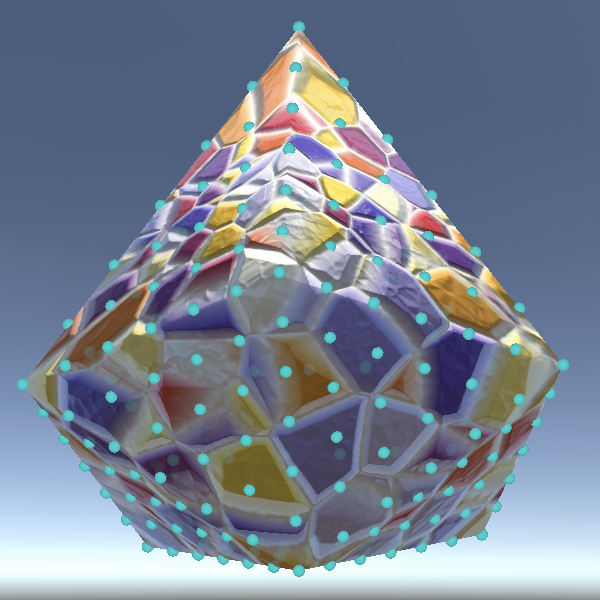
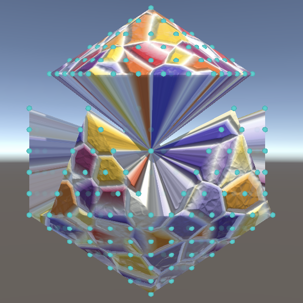
From Octasphere to Icosphere
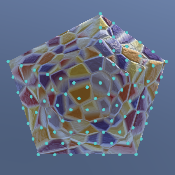
An icosahedron has twelve corners: a south and north pole, plus two rings of five vertices each in between. At the poles five triangle faces meet, forming the polar caps. In between those fits a ring of ten triangles, for a total of twenty faces.
We can morph an octahedron layout into an icosahedron layout by adding a fifth rhombus, then doubling the V dimension of these rhombuses so they become parallelograms, forming strips of four triangles going from pole to pole.
To make the transformation easier to see, turn the octasphere back into an octahedron by removing the normalization of the vertex positions. To fit five rhombuses in a circle we have to work with 72° rotation increments instead of 90°, which complicates things. Let's create a convenient static method that creates a point with X and Z coordinates rotated based on the rhombus identifier, starting with the back vector: `[[sin((2pi)/5i)],[0],[-cos((2pi)/5i)]]` Use it to create the five rhombuses in At this point we get a misshapen octahedron. The next step is to add vertices and triangles for a fifth rhombus. Increase the vertex count, index count, and job length accordingly. Adjust the U coordinate and rhombus identifier in We also have to adjust the Z index of the first rhombus before the loop. And also afterwards. To make the full transition to icosahedron we have to elongate our rhombuses, which means that the Rename And also rename the variable in To make sure that we end up with equilateral triangles the corner rings must have the appropriate radius and vertical position. We can do this for the low ring by setting its Y coordinate to −½ and then scaling everything by `2/5sqrt(5)`. To make clear that those corners are for the low ring, let's refactor rename the fields to To also support the high ring, add two more corners to Compared to the low ring, the high ring is rotated `pi/5` radians clockwise and its Y coordinates are positive instead of negative. To make To keep the results of This is repetitive code, which we can reduce to just a few lines by directly using the strip identifier to calculate the correct arguments for Unfortunately the Burst compiler now considers all code variable, which makes our Burst code perform trigonometry instead of copying a few constant values. We can force the compiler to again treat the corner data as constant by reintroducing the switch and moving the strip-creating code to a new Now add the high corners to To fill the entire strips we have to double the effective resolution in the V dimension. Add a convenient private property to reference it. Adjust the vertex count and index count to use this increased resolution, still using the regular one for the U dimension. Also adjust the vertex and triangle index offsets at the start of And incorporate it into the initial quad indices. The loop along the V dimension also becomes longer, as well as the quad Z index increase for the first column. And update the quad Z index for the first column after the loop as well. We need to make one additional change to make sure that all triangle indices are correct. Because the strips are longer they now connect to three icosahedron edges of their neighbor instead of two octahedron edges. This new edge affects the first column. Only the first edge requires incrementing the quad Z index inside the loop by an entire column. This is the case when `v<=r_u-u`, where `r_u` is the U resolution. In all other cases we only have to add 1. The loop can now also go through four different faces instead of just two. The first face is still `v<=r_u-u`. The second face comes after that, as long as `v<r_u`. The third face comes after that, as long as `v<=r_v-u`, so based on the V dimension this time, and the last one comes after that. Let's initially set the positions for the two new faces to zero, keeping the top and bottom faces as they were. Also, the last face's interpolator should be reduced by one. To fix the top of the icosahedron we have to adjust the data for the top face. It must be relative to the high corners instead of relative to the low corners. The data for the second face—the low triangle of the ring—is calculated the same way as the top face, as both triangles are pointing up, but it's relative to different corners. It goes from the low corners to the high right corner. Add the interpolation for it to the loop, with `v/r_u` as the interpolator. The third face—the high triangle of the ring—is calculated the same way as the bottom face, as both triangles are pointing down, but once again relative to different corners. It goes from the low left corner to the high corners. Add the interpolation for it to the loop as well, with `v/r_u-1` as the interpolator, completing the icosahedron. To produce the icosphere we have to reintroduce normalization of the vertex position vectors.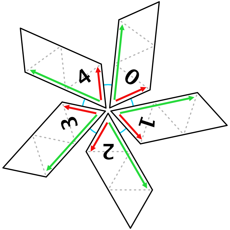
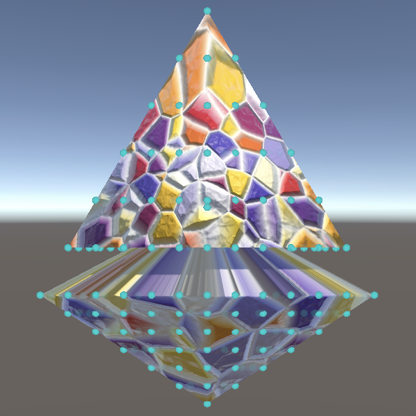
Octahedron
			vertex.position = columnBottomStart;
			streams.SetVertex(vi, vertex);
			vi += 1;

			for (int v = 1; v < Resolution; v++, vi++, ti += 2) {
				…
				//vertex.position = normalize(vertex.position);
				…
			}
Five Rhombuses
		static float3 GetCorner (int id) => float3(
			sin(0.4f * PI * id),
			0f,
			-cos(0.4f * PI * id)
		);
GetRhombus. static Rhombus GetRhombus (int id) => id switch {
0 => new Rhombus {
id = id,
leftCorner = GetCorner(0),
rightCorner = GetCorner(1)
},
1 => new Rhombus {
id = id,
leftCorner = GetCorner(1),
rightCorner = GetCorner(2)
},
2 => new Rhombus {
id = id,
leftCorner = GetCorner(2),
rightCorner = GetCorner(3)
},
3 => new Rhombus {
id = id,
leftCorner = GetCorner(3),
rightCorner = GetCorner(4)
},
_ => new Rhombus {
id = id,
leftCorner = GetCorner(4),
rightCorner = GetCorner(0)
}
};
		public int VertexCount => 5 * Resolution * Resolution + 2;

		public int IndexCount => 6 * 5 * Resolution * Resolution;

		public int JobLength => 5 * Resolution;
Execute as well. int u = i / 5;
Rhombus rhombus = GetRhombus(i - 5 * u);
			int4 quad = int4(
				vi,
				firstColumn ? 0 : vi - Resolution,
				firstColumn ?
					rhombus.id == 0 ?
						4 * Resolution * Resolution + 2 :
						vi - Resolution * (Resolution + u) :
					vi - Resolution + 1,
				vi + 1
			);
			if (!firstColumn) {
				quad.z = Resolution * Resolution * (rhombus.id == 0 ? 5 : rhombus.id) -
					Resolution + u + 1;
			}
Five Strips
Rhombus type name is no longer appropriate. They will become parallelograms, but to keep the name short we'll refactor rename the type to Strip. struct Strip {
public int id;
public float3 leftCorner, rightCorner;
}
GetRhombus to GetStrip to match. static Strip GetStrip (int id) => id switch { … };
Execute. As usual for a refactor rename, I don't show all the required code changes. public void Execute<S> (int i, S streams) where S : struct, IMeshStreams {
int u = i / 5;
Strip strip = GetStrip(i - 5 * u);
…
}
Low Corner Ring
		static float3 GetCorner (int id) => float3(
			0.4f * sqrt(5f) * sin(0.4f * PI * id),
			-0.2f * sqrt(5f),
			-0.4f * sqrt(5f) * cos(0.4f * PI * id)
		);
lowLeftCorner and LowRightCorner. struct Strip {
public int id;
public float3 lowLeftCorner, lowRightCorner;
}
Both Rings
Strip.
public float3 lowLeftCorner, lowRightCorner, highLeftCorner, highRightCorner;
GetCorner support both rings halve its radian scalar and add an integer parameter to control the sign of the Y coordinate via multiplication. static float3 GetCorner (int id, int ySign) => float3(
0.4f * sqrt(5f) * sin(0.2f * PI * id),
ySign * 0.2f * sqrt(5f),
-0.4f * sqrt(5f) * cos(0.2f * PI * id)
);
GetStrip the same we now have to double the first argument passed to GetCorner and use −1 for its new second argument. static Strip GetStrip (int id) => id switch {
0 => new Strip {
id = id,
lowLeftCorner = GetCorner(0, -1),
lowRightCorner = GetCorner(2, -1)
},
1 => new Strip {
id = id,
lowLeftCorner = GetCorner(2, -1),
lowRightCorner = GetCorner(4, -1)
},
2 => new Strip {
id = id,
lowLeftCorner = GetCorner(4, -1),
lowRightCorner = GetCorner(6, -1)
},
3 => new Strip {
id = id,
lowLeftCorner = GetCorner(6, -1),
lowRightCorner = GetCorner(8, -1)
},
_ => new Strip {
id = id,
lowLeftCorner = GetCorner(8, -1),
lowRightCorner = GetCorner(0, -1)
}
};
GetCorner. static Strip GetStrip (int id) => new Strip {
id = id,
lowLeftCorner = GetCorner(2 * id, -1),
lowRightCorner = GetCorner(id == 4 ? 0 : 2 * id + 2, -1)
};
CreateStrip method. static Strip GetStrip (int id) => id switch {
0 => CreateStrip(0),
1 => CreateStrip(1),
2 => CreateStrip(2),
3 => CreateStrip(3),
_ => CreateStrip(4)
};
static Strip CreateStrip (int id) => new Strip {
id = id,
lowLeftCorner = GetCorner(2 * id, -1),
lowRightCorner = GetCorner(id == 4 ? 0 : 2 * id + 2, -1)
};
CreateStip. Their identifier arguments are one less than the respective low corners, with correct wrapping for the first strip. Their Y sign is positive. static Strip CreateStrip (int id) => new Strip {
id = id,
lowLeftCorner = GetCorner(2 * id, -1),
lowRightCorner = GetCorner(id == 4 ? 0 : 2 * id + 2, -1),
highLeftCorner = GetCorner(id == 0 ? 9 : 2 * id - 1, 1),
highRightCorner = GetCorner(2 * id + 1, 1)
};
Entire Strips
int ResolutionV => 2 * Resolution;
		public int VertexCount => 5 * ResolutionV * Resolution + 2;

		public int IndexCount => 6 * 5 * ResolutionV * Resolution;
Execute to match. int vi = ResolutionV * (Resolution * strip.id + u) + 2;
int ti = 2 * ResolutionV * (Resolution * strip.id + u);
			int4 quad = int4(
				vi,
				firstColumn ? 0 : vi - ResolutionV,
				firstColumn ?
					strip.id == 0 ?
						4 * ResolutionV * Resolution + 2 :
						vi - ResolutionV * (Resolution + u) :
					vi - ResolutionV + 1,
				vi + 1
			);
			for (int v = 1; v < ResolutionV; v++, vi++, ti += 2) {
				…
				quad += int4(1, 0, firstColumn ? ResolutionV : 1, 1);
			}
			if (!firstColumn) {
				quad.z = ResolutionV * Resolution * (strip.id == 0 ? 5 : strip.id) -
					Resolution + u + 1;
			}
				quad +=
					int4(1, 0, firstColumn && v <= Resolution - u ? ResolutionV : 1, 1);
				if (v <= Resolution - u) {
					vertex.position =
						lerp(columnBottomStart, columnBottomEnd, (float)v / Resolution);
				}
				else if (v < Resolution) {
					vertex.position = 0f;
				}
				else if (v <= ResolutionV - u) {
					vertex.position = 0f;
				}
				else {
					vertex.position =
						lerp(columnTopStart, columnTopEnd, (float)v / Resolution - 1f);
				}
Completing the Icosahedron
			float3 columnTopDir = up() - strip.highLeftCorner;
			float3 columnTopStart =
				strip.highRightCorner + columnTopDir * ((float)u / Resolution - 1f);
			float3 columnTopEnd = strip.highLeftCorner + columnTopDir * u / Resolution;
			float3 columnLowDir = strip.highRightCorner - strip.lowLeftCorner;
			float3 columnLowStart =
				strip.lowRightCorner + columnLowDir * ((float)u / Resolution - 1f);
			float3 columnLowEnd = strip.lowLeftCorner + columnLowDir * u / Resolution;

			float3 columnTopDir = up() - strip.highLeftCorner;
			float3 columnTopStart =
				strip.highRightCorner + columnTopDir * ((float)u / Resolution - 1f);
			float3 columnTopEnd = strip.highLeftCorner + columnTopDir * u / Resolution;
				else if (v < Resolution) {
					vertex.position =
						lerp(columnLowStart, columnLowEnd, (float)v / Resolution);
				}
			float3 columnBottomDir = strip.lowRightCorner - down();
			float3 columnBottomStart = down() + columnBottomDir * u / Resolution;
			float3 columnBottomEnd =
				strip.lowLeftCorner + columnBottomDir * u / Resolution;

			float3 columnLowDir = strip.highRightCorner - strip.lowLeftCorner;
			float3 columnLowStart =
				strip.lowRightCorner + columnLowDir * ((float)u / Resolution - 1f);
			float3 columnLowEnd = strip.lowLeftCorner + columnLowDir * u / Resolution;

			float3 columnHighDir = strip.highRightCorner - strip.lowLeftCorner;
			float3 columnHighStart = strip.lowLeftCorner + columnHighDir * u / Resolution;
			float3 columnHighEnd = strip.highLeftCorner + columnHighDir * u / Resolution;
				else if (v <= ResolutionV - u) {
					vertex.position =
						lerp(columnHighStart, columnHighEnd, (float)v / Resolution - 1f);
				}
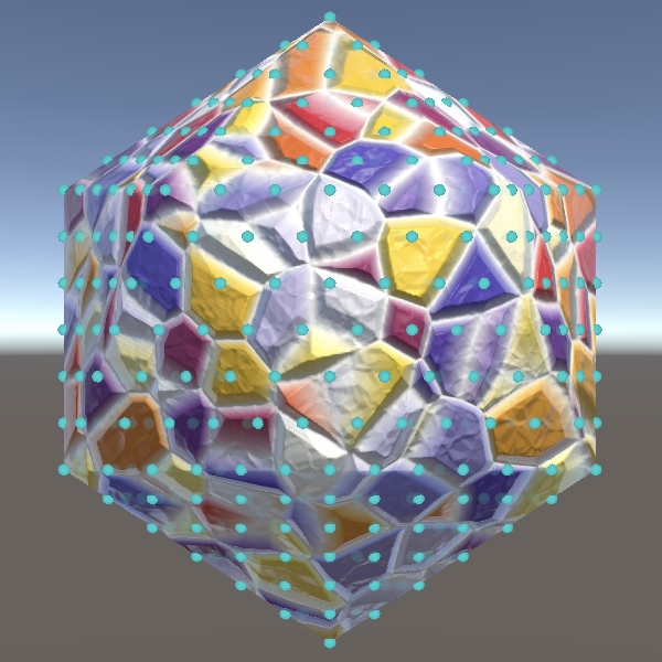
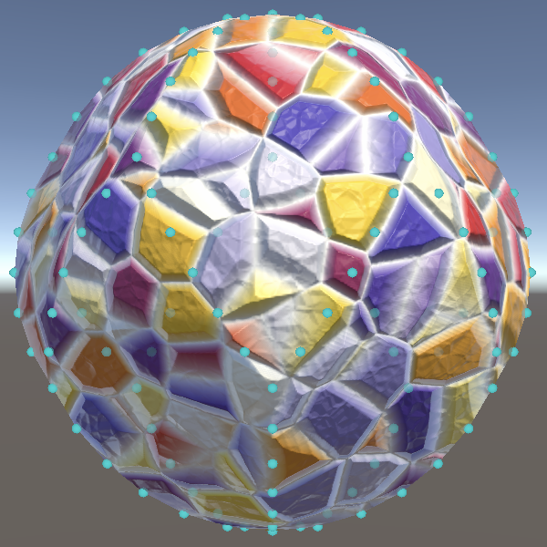
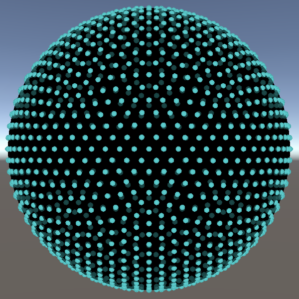
Sphere
			vertex.position = normalize(columnBottomStart);
			streams.SetVertex(vi, vertex);
			vi += 1;

			for (int v = 1; v < ResolutionV; v++, vi++, ti += 2) {
				…
				vertex.position = normalize(vertex.position);
				streams.SetVertex(vi, vertex);
				…
			}

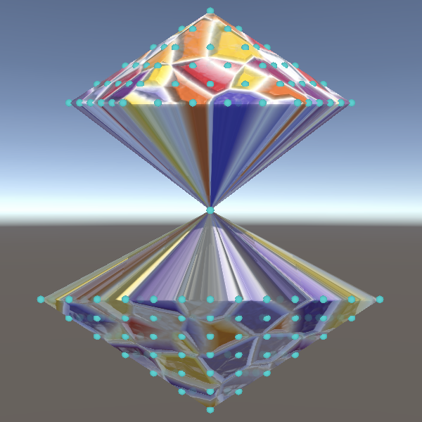
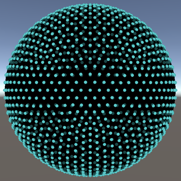
Geodesic Icosphere
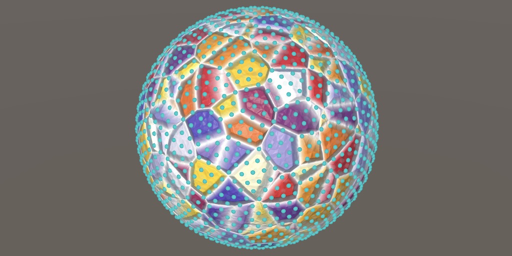
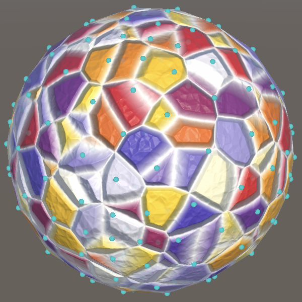
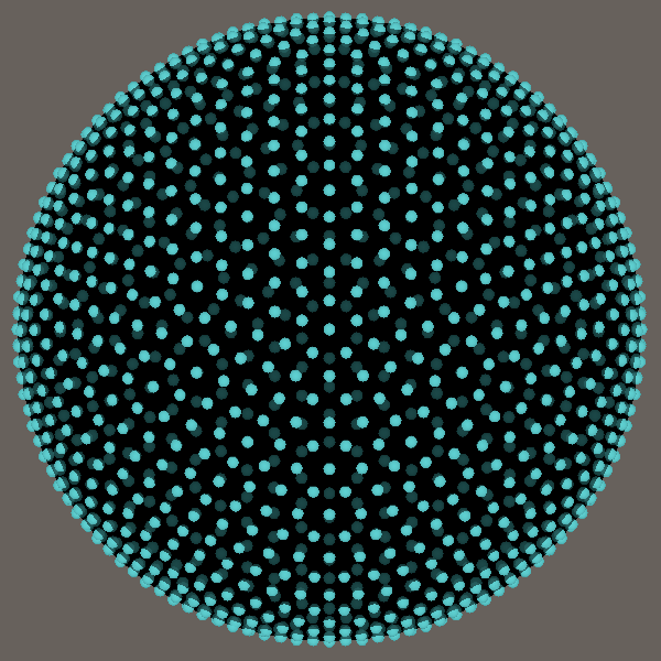
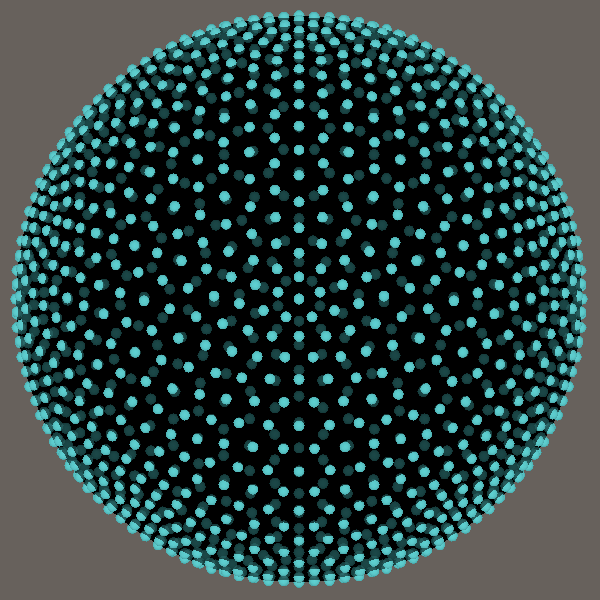
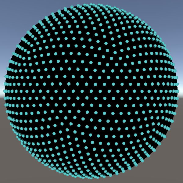
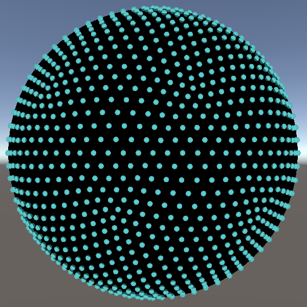
Just like with the octasphere, the vertices of the icosphere bunch up near the corners of the underlying shape. Because the icosahedron has more corners than the octahedron—twelve instead of eight—and at each corner five face meet instead of four, the bunching up is less severe, but it still happens. We can again use geodesic lines to alleviate this phenomenon.
Alternative Icosphere
Duplicate Icosphere and rename it to GeoIcosphere.
public struct GeoIcosphere : IMeshGenerator { … }
And add an option for it to ProceduralMesh.
	static MeshJobScheduleDelegate[] jobs = {
		…
		MeshJob<Icosphere, PositionStream>.ScheduleParallel,
		MeshJob<GeoIcosphere, PositionStream>.ScheduleParallel,
		…
	};

	public enum MeshType {
		SquareGrid€, SharedSquareGrid€, SharedTriangleGrid€,
		FlatHexagonGrid€, PointyHexagonGrid€, CubeSphere€, SharedCubeSphere€,
		Icosphere€, GeoIcosphere€, Octasphere€, GeoOctasphere€, UVSphere€
	};
Edge Rotation Axes
The conversion from a normalization approach to a geodesic approach is the same as for the octasphere, except that the vertical icosahedron edges are not on the XY and YZ planes. So we need to also generate a rotation axis for each of those edges.
Each triangle face has two edges, so we need an axis for each. However, the two middle faces of the strip—those forming the ring—share the same middle edge, so we only need seven different axes. Add fields for them to Strip.
		struct Strip {
			public int id;
			public float3 lowLeftCorner, lowRightCorner, highLeftCorner, highRightCorner;
			public float3
				bottomLeftAxis, bottomRightAxis,
				midLeftAxis, midCenterAxis, midRightAxis,
				topLeftAxis, topRightAxis;
		}
The bottom left axis can be found by taking the normalized cross product of the south pole and the low left corner position vectors. Likewise for the bottom right axis. Adjust CreateStip so it calculates these axes based on the previously-defined corners.
		static Strip CreateStrip (int id) {
			var s = new Strip {
				id = id,
				lowLeftCorner = GetCorner(2 * id, -1),
				lowRightCorner = GetCorner(id == 4 ? 0 : 2 * id + 2, -1),
				highLeftCorner = GetCorner(id == 0 ? 9 : 2 * id - 1, 1),
				highRightCorner = GetCorner(2 * id + 1, 1)
			};
			s.bottomLeftAxis = normalize(cross(down(), s.lowLeftCorner));
			s.bottomRightAxis = normalize(cross(down(), s.lowRightCorner));
			return s;
		}
The top axes are found the same way, using the appropriate high corner and the north pole.
			s.bottomLeftAxis = normalize(cross(down(), s.lowLeftCorner));
			s.bottomRightAxis = normalize(cross(down(), s.lowRightCorner));
			s.topLeftAxis = normalize(cross(s.highLeftCorner, up()));
			s.topRightAxis = normalize(cross(s.highRightCorner, up()));
And the middle axes fit in between, stiching them together.
			s.bottomLeftAxis = normalize(cross(down(), s.lowLeftCorner));
			s.bottomRightAxis = normalize(cross(down(), s.lowRightCorner));
			s.midLeftAxis = normalize(cross(s.lowLeftCorner, s.highLeftCorner));
			s.midCenterAxis = normalize(cross(s.lowLeftCorner, s.highRightCorner));
			s.midRightAxis = normalize(cross(s.lowRightCorner, s.highRightCorner));
			s.topLeftAxis = normalize(cross(s.highLeftCorner, up()));
			s.topRightAxis = normalize(cross(s.highRightCorner, up()));
Geodesic Column Start
We begin by adjusting the first position of each column. We need to use quaternion for that, which we again have to explicitly use to avoid a type name clash.
using quaternion = Unity.Mathematics.quaternion;
To know by how much to rotate we need to know the angle between icosahedron corners that share an edge. This angle is always the same, so we'll introduce a private EdgeRotationAngle property for it. We can use any two corners with the correct relationship to calculate it.
static float EdgeRotationAngle => acos(dot(up(), GetCorner(0, 1)));
Now we can put the first position of each column in Execute on a geodesic line, by rotating the south pole around the bottom right axis and scaling the rotation angle by `u/r_u`.
			vertex.position = mul(
				quaternion.AxisAngle(
					strip.bottomRightAxis, EdgeRotationAngle * u / Resolution
				),
				down()
			);
			streams.SetVertex(vi, vertex);
			vi += 1;
At this point there isn't much of a visual difference yet.
Geodesic Edges
The next step is to use the edge rotation axes to find the appropriate points on the vertical edges that will be used to calculate the final rotation across the face. For this we again need to calculate `h=u+v` inside the loop. We also need to determine which two axes and start positions to use for the left and right side, so add variables for those.
			for (int v = 1; v < ResolutionV; v++, vi++, ti += 2) {
				float h = u + v;
				float3 leftAxis, rightAxis, leftStart, rightStart;
				…
			}
We replace the code that does the linear interpolation with new code that sets those axes and positions. The first face uses the bottom left and right axes and the start position is the south pole for both sides.
				if (v <= Resolution - u) {
					leftAxis = strip.bottomLeftAxis;
					rightAxis = strip.bottomRightAxis;
					leftStart = rightStart = down();
				}
The second face uses the mid center and mid right axes for the left and right edges, and the low left and low right corners as starting positions.
				else if (v < Resolution) {
					leftAxis = strip.midCenterAxis;
					rightAxis = strip.midRightAxis;
					leftStart = strip.lowLeftCorner;
					rightStart = strip.lowRightCorner;
				}
The third face uses the mid left and mid center axes, along with the low left corner.
				else if (v <= ResolutionV - u) {
					leftAxis = strip.midLeftAxis;
					rightAxis = strip.midCenterAxis;
					leftStart = rightStart = strip.lowLeftCorner;
				}
The fourth face uses the top axes and high corners.
				else {
					leftAxis = strip.topLeftAxis;
					rightAxis = strip.topRightAxis;
					leftStart = strip.highLeftCorner;
					rightStart = strip.highRightCorner;
				}
We also need to know by how much to scale the edge angle. This factor is `h/r_u` for the first face, `h/r_u-1` for the middle two faces, and `h/r_u-2` for the fourth face.
				float edgeAngleScale;
				if (v <= Resolution - u) {
					…
					edgeAngleScale = h / Resolution;
				}
				else if (v < Resolution) {
					…
					edgeAngleScale = h / Resolution - 1f;
				}
				else if (v <= ResolutionV - u) {
					…
					edgeAngleScale = h / Resolution - 1f;
				}
				else {
					…
					edgeAngleScale = h / Resolution - 2f;
				}
After we have determined these values we can perform the rotations to create pLeft and pRight and then use those to find the final position like we did for the geodesic octasphere. But let's initially leave the final rotation angle unscaled so we end up with only the vertical geodesic edge lines.
				float3 pLeft = mul(
					quaternion.AxisAngle(leftAxis, EdgeRotationAngle * edgeAngleScale),
					leftStart
				);
				float3 pRight = mul(
					quaternion.AxisAngle(rightAxis, EdgeRotationAngle * edgeAngleScale),
					rightStart
				);
				float3 axis = normalize(cross(pRight, pLeft));
				float angle = acos(dot(pRight, pLeft));
				vertex.position = mul(
					quaternion.AxisAngle(axis, angle), pRight
				);
All Geodesic Lines
In the case of the geodesic octasphere the scale of the final rotation angle is `v/h` for the first face and `(r-u)/(2r-h)` for the second face of the rhombus. To make it work for the four faces of the icosahedron strip we need to use `v/h` for the first face, `(r_u-u)/(r_v-h)` for the second, `(v-r_u)/(h-r_u)` for the third, and `(r_u-u)/(3r_u-h)` for the fourth. Use that to scale the final rotation angle.
				float edgeAngleScale, faceAngleScale;
				if (v <= Resolution - u) {
					…
					faceAngleScale = v / h;
				}
				else if (v < Resolution) {
					…
					faceAngleScale = (Resolution - u) / (ResolutionV - h);
				}
				else if (v <= ResolutionV - u) {
					…
					faceAngleScale = (v - Resolution) / (h - Resolution);
				}
				else {
					…
					faceAngleScale = (Resolution - u) / (3f * Resolution - h);
				}

				…
				float angle = acos(dot(pRight, pLeft)) * faceAngleScale;
With our geodesic icosphere finished we can remove all old code that calculate the values used for the linear interpolation.
//float3 columnBottomDir = strip.lowRightCorner - down();//…//float3 columnTopEnd = strip.highLeftCorner + columnTopDir * u / Resolution;
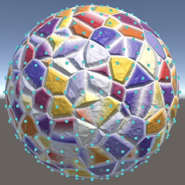
Comparison
When comparing both approaches it becomes clear that the geodesic variant indeed gets rid of some bunching up near the poles, although the difference isn't as stark as for the octasphere. So the geodesic icosphere can be considered better in that regard, but just like for the octasphere its vertex distribution is less symmetrical than the normalized variant.
Want to know when the next tutorial gets released? Keep tabs on my Patreon page!