Rounded Cube
Building in 3D
- Create a cube with a seamless mesh.
- Add rounded edges to the cube.
- Define normals.
- Use sub-meshes.
- Create a custom shader.
- Combine primitive colliders.
In this tutorial we'll create a rounded cube with a single mesh.
This tutorial follows Procedural Grid. It has been made for Unity 5.0.1 and up.
Compositing a Cube
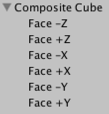
After tackling 2D grids, the next logical step is to procedurally generate 3D structures. Let's have a look at a cube. Conceptually, it consists of six 2D faces that are positioned and rotated such that they enclose a 3D volume. We can do this with six instances of our grid.
Our grid lies in the XY plane and faces the negative Z direction. This is the -Z face of the cube. You can create the +Z face by duplicating it, settings its Y rotation to 180°, and repositioning it so both faces line up.
The -X and +X faces are created the same way, but with Y rotations of 90° and 270°. You can also give these faces a different xSize than the Z faces if you want to, but their ySize must match. The four faces must be aligned so they form a closed ring.
The -Y and +Y faces are made with X rotations of 270° and 90°. Their xSize should match those of the Z faces, and their ySize should match the xSize of the X faces.
This gives us a cube that consists of six separate meshes. While it looks fine and is a good reference, it isn't very practical. We could combine the meshes via Mesh.CombineMeshes, but we might as well create the whole cube at once.
Creating Cube Vertices
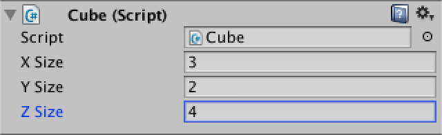
To create our own cube, we need to create a new component script. Let's bootstrap it by recycling some code from the previous tutorial. The only new thing right now is the third dimension, so we have to add zSize. I once again use a coroutine and gizmos to help visualize what's going on.
using UnityEngine;
using System.Collections;

[RequireComponent(typeof(MeshFilter), typeof(MeshRenderer))]
public class Cube : MonoBehaviour {

	public int xSize, ySize, zSize;

	private Mesh mesh;
	private Vector3[] vertices;

	private void Awake () {
		StartCoroutine(Generate());
	}

	private IEnumerator Generate () {
		GetComponent<MeshFilter>().mesh = mesh = new Mesh();
		mesh.name = "Procedural Cube";
		WaitForSeconds wait = new WaitForSeconds(0.05f);

		yield return wait;
	}

	private void OnDrawGizmos () {
		if (vertices == null) {
			return;
		}
		Gizmos.color = Color.black;
		for (int i = 0; i < vertices.Length; i++) {
			Gizmos.DrawSphere(vertices[i], 0.1f);
		}
	}
}
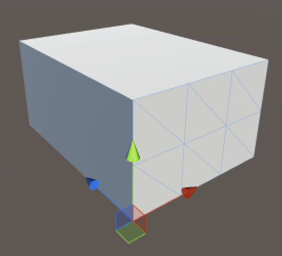
Now you can add a new game object to the scene and turn it into a cube by adding this component. Or replace the grid component of an existing object.
Before we can add the vertices of our cube, we first have to know how many there are. We already know the amount of vertices needed for a single face.
`(#x + 1)(#y + 1)`
So we can just add these six faces together to get the total.
`2( (#x + 1)(#y + 1) + (#x + 1)(#z + 1) + (#y + 1)(#z + 1) )`
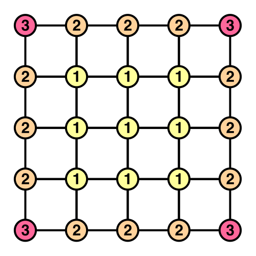
However, As the edges of the faces touch each other, their vertices will overlap, which leads to duplicate vertices. Each of the cube's corner vertices are tripled, while all vertices along its edges are doubled.
This doesn't need to be a problem. In fact, vertex duplication is very common, as it is used to create sharp edges in a mesh with normals. So we can create the six faces completely separate from one another, just combined in a single array.
But that's not what we're going to do, because we already know how to create grids. Our cube won't have duplicate vertices. It's more interesting that way.
So how many vertices do we need? Let's break it down by type. First we have eight corner vertices, that's easy. Then we have twelve edges, four in each direction. As we don't include the corners, each edge has an amount of vertices equal to the corresponding size minus one. Alternatively, think of it as four sets of an X, Y, and Z edge.
`4(#x + #y + #z - 3)`
The remaining vertices are those that lie inside the faces. That's equal to a cube with duplicated vertices that has its size reduced by two.
`2( (#x - 1)(#y - 1) + (#x - 1)(#z - 1) + (#y - 1)(#z - 1) )`
Now we finally know how many vertices we need.
	private IEnumerator Generate () {
		GetComponent<MeshFilter>().mesh = mesh = new Mesh();
		mesh.name = "Procedural Cube";
		WaitForSeconds wait = new WaitForSeconds(0.05f);

		int cornerVertices = 8;
		int edgeVertices = (xSize + ySize + zSize - 3) * 4;
		int faceVertices = (
			(xSize - 1) * (ySize - 1) +
			(xSize - 1) * (zSize - 1) +
			(ySize - 1) * (zSize - 1)) * 2;
		vertices = new Vector3[cornerVertices + edgeVertices + faceVertices];

		yield return wait;
	}
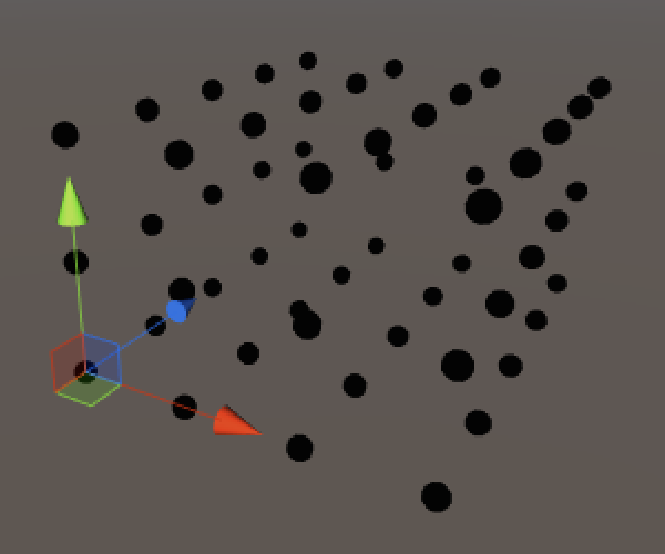
Positioning the vertices of the first face row is exactly like positioning the first row of a grid.
		vertices = new Vector3[cornerVertices + edgeVertices + faceVertices];

		int v = 0;
		for (int x = 0; x <= xSize; x++) {
			vertices[v++] = new Vector3(x, 0, 0);
			yield return wait;
		}
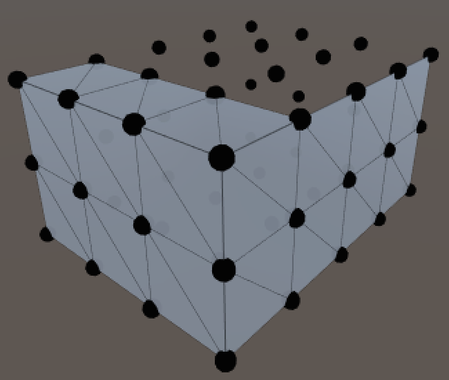
Then it gets more interesting. Let's continue with the first row of the second face, and so on, creating a square ring of vertices. This is done by looping four times, using different ranges and positions.
		for (int x = 0; x <= xSize; x++) {
			vertices[v++] = new Vector3(x, 0, 0);
			yield return wait;
		}
		for (int z = 1; z <= zSize; z++) {
			vertices[v++] = new Vector3(xSize, 0, z);
			yield return wait;
		}
		for (int x = xSize - 1; x >= 0; x--) {
			vertices[v++] = new Vector3(x, 0, zSize);
			yield return wait;
		}
		for (int z = zSize - 1; z > 0; z--) {
			vertices[v++] = new Vector3(0, 0, z);
			yield return wait;
		}
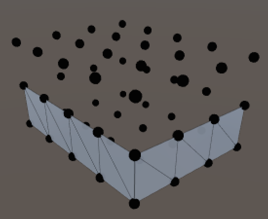
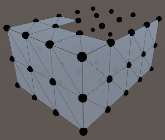
We can turn this into a complete wrap around the cube's height by repeating the ring placement along Y.
		int v = 0;
		for (int y = 0; y <= ySize; y++) {
			for (int x = 0; x <= xSize; x++) {
				vertices[v++] = new Vector3(x, y, 0);
				yield return wait;
			}
			for (int z = 1; z <= zSize; z++) {
				vertices[v++] = new Vector3(xSize, y, z);
				yield return wait;
			}
			for (int x = xSize - 1; x >= 0; x--) {
				vertices[v++] = new Vector3(x, y, zSize);
				yield return wait;
			}
			for (int z = zSize - 1; z > 0; z--) {
				vertices[v++] = new Vector3(0, y, z);
				yield return wait;
			}
		}
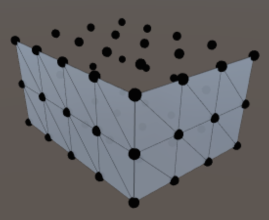
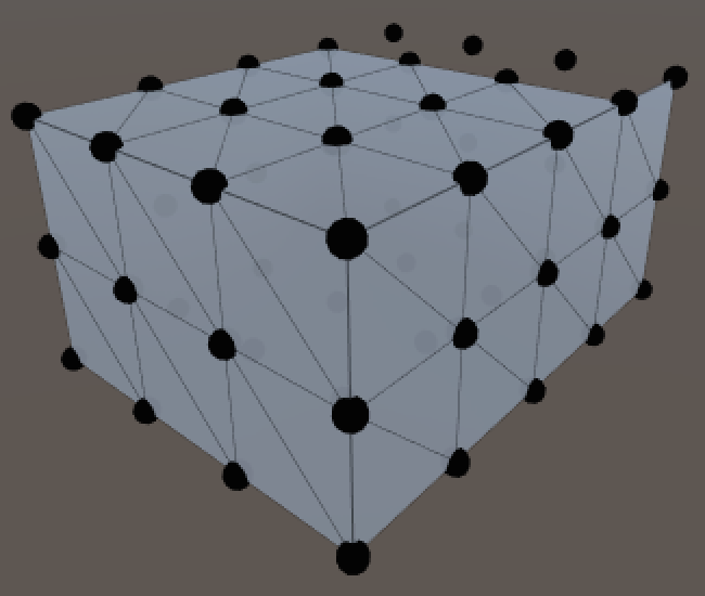
After that we have to cap the top and bottom. I just fill the holes like a regular grid.
		for (int z = 1; z < zSize; z++) {
			for (int x = 1; x < xSize; x++) {
				vertices[v++] = new Vector3(x, ySize, z);
				yield return wait;
			}
		}
		for (int z = 1; z < zSize; z++) {
			for (int x = 1; x < xSize; x++) {
				vertices[v++] = new Vector3(x, 0, z);
				yield return wait;
			}
		}
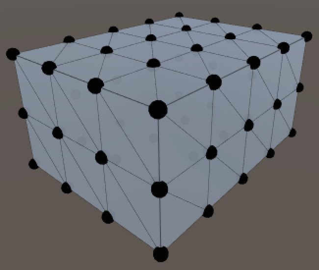
Adding the Triangles
Now that the vertices are correctly positions and we're familiar with the order in which they are placed, we can move on to the triangles. To prepare for that, I have removed the coroutine stuff, and added separate methods for the creation of vertices and triangles. And of course the vertices need to be assigned to the mesh.
Prepare. Remove yield statements for vertices.
	private void Awake () {
		Generate();
	}

	private void Generate () {
		GetComponent<MeshFilter>().mesh = mesh = new Mesh();
		mesh.name = "Procedural Cube";
		CreateVertices();
		CreateTriangles();
	}

	private void CreateVertices () {
		…

		mesh.vertices = vertices;
	}

	private void CreateTriangles () {
	}
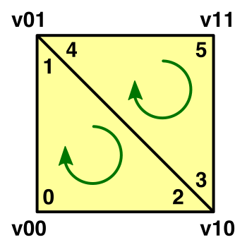
The creation of a single quad is exactly the same as for the grid. As we'll end up creating quads in multiple places, it's a good idea to create a method for it.
	private static int
	SetQuad (int[] triangles, int i, int v00, int v10, int v01, int v11) {
		triangles[i] = v00;
		triangles[i + 1] = triangles[i + 4] = v01;
		triangles[i + 2] = triangles[i + 3] = v10;
		triangles[i + 5] = v11;
		return i + 6;
	}
Unlike vertices, the number of triangles is simply equal to that of the six faces combined. It doesn't matter whether they use shared vertices or not.
	private void CreateTriangles () {
		int quads = (xSize * ySize + xSize * zSize + ySize * zSize) * 2;
		int[] triangles = new int[quads * 6];
		mesh.triangles = triangles;
	}
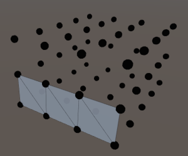
Creating the first triangle row is once again the same as for a grid. The only difference so far is that the offset for the vertices in the next row is equal to an entire ring of vertices.
	private void CreateTriangles () {
		int quads = (xSize * ySize + xSize * zSize + ySize * zSize) * 2;
		int[] triangles = new int[quads * 6];
		int ring = (xSize + zSize) * 2;
		int t = 0, v = 0;

		for (int q = 0; q < xSize; q++, v++) {
			t = SetQuad(triangles, t, v, v + 1, v + ring, v + ring + 1);
		}

		mesh.triangles = triangles;
	}
To triangulate an entire ring, let's just be naive and lengthen the loop to go all the way around.
		for (int q = 0; q < ring; q++, v++) {
			t = SetQuad(triangles, t, v, v + 1, v + ring, v + ring + 1);
		}
This works, except for the last quad. Its second and fourth vertex need to rewind to the start of the ring. So extract it from the loop.
		for (int q = 0; q < ring - 1; q++, v++) {
			t = SetQuad(triangles, t, v, v + 1, v + ring, v + ring + 1);
		}
		t = SetQuad(triangles, t, v, v - ring + 1, v + ring, v + 1);
To triangulate all rings, once again simply repeat the process along Y. Notice that the vertex index needs to be increased after each ring, because our ring loops are one step shorter.
		for (int y = 0; y < ySize; y++, v++) {
			for (int q = 0; q < ring - 1; q++, v++) {
				t = SetQuad(triangles, t, v, v + 1, v + ring, v + ring + 1);
			}
			t = SetQuad(triangles, t, v, v - ring + 1, v + ring, v + 1);
		}
Unfortunately the top and bottom faces are not as straightforward. Their vertex layout is like a grid surrounded by a ring.
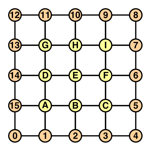
Let's start with the top face, giving it its own method.
	private void CreateTriangles () {
		…

		t = CreateTopFace(triangles, t, ring);
		mesh.triangles = triangles;
	}
The first row follows the familiar pattern. This works because the first row of the inner grid was added directly after the spiral ended. The final quad's fourth vertex is different though, as that's where the ring bends upwards.
	private int CreateTopFace (int[] triangles, int t, int ring) {
		int v = ring * ySize;
		for (int x = 0; x < xSize - 1; x++, v++) {
			t = SetQuad(triangles, t, v, v + 1, v + ring - 1, v + ring);
		}
		t = SetQuad(triangles, t, v, v + 1, v + ring - 1, v + 2);

		return t;
	}
It gets more complicated for the next row. It is useful to keep track of the row's minimum vertex index, which lies on the ring. The other index to track is for the middle part, which is the grid.
		…

		int vMin = ring * (ySize + 1) - 1;
		int vMid = vMin + 1;

		t = SetQuad(triangles, t, vMin, vMid, vMin - 1, vMid + xSize - 1);

		return t;
The middle part of the row is quite like a regular grid.
		t = SetQuad(triangles, t, vMin, vMid, vMin - 1, vMid + xSize - 1);
		for (int x = 1; x < xSize - 1; x++, vMid++) {
			t = SetQuad(
				triangles, t,
				vMid, vMid + 1, vMid + xSize - 1, vMid + xSize);
		}
The last quad of the row once again has to deal with the outer ring, so let's track the maximum vertex as well.
		int vMin = ring * (ySize + 1) - 1;
		int vMid = vMin + 1;
		int vMax = v + 2;

		t = SetQuad(triangles, t, vMin, vMid, vMin - 1, vMid + xSize - 1);
		for (int x = 1; x < xSize - 1; x++, vMid++) {
			t = SetQuad(
				triangles, t,
				vMid, vMid + 1, vMid + xSize - 1, vMid + xSize);
		}
		t = SetQuad(triangles, t, vMid, vMax, vMid + xSize - 1, vMax + 1);
This can be turned into a loop to take care of all but the last row. Each iteration the middle and maximum vertex index needs to be incremented. The minimum vertex index decreases instead, because of the orientation of the ring.
		for (int z = 1; z < zSize - 1; z++, vMin--, vMid++, vMax++) {
			t = SetQuad(triangles, t, vMin, vMid, vMin - 1, vMid + xSize - 1);
			for (int x = 1; x < xSize - 1; x++, vMid++) {
				t = SetQuad(
					triangles, t,
					vMid, vMid + 1, vMid + xSize - 1, vMid + xSize);
			}
			t = SetQuad(triangles, t, vMid, vMax, vMid + xSize - 1, vMax + 1);
		}
Let's introduce the top vertex index, then use it to set the first quad of the last row.
		int vTop = vMin - 2;
		t = SetQuad(triangles, t, vMin, vMid, vTop + 1, vTop);
Then loop through the middle of the row.
		int vTop = vMin - 2;
		t = SetQuad(triangles, t, vMin, vMid, vTop + 1, vTop);
		for (int x = 1; x < xSize - 1; x++, vTop--, vMid++) {
			t = SetQuad(triangles, t, vMid, vMid + 1, vTop, vTop - 1);
		}
And finally the last quad.
		int vTop = vMin - 2;
		t = SetQuad(triangles, t, vMin, vMid, vTop + 1, vTop);
		for (int x = 1; x < xSize - 1; x++, vTop--, vMid++) {
			t = SetQuad(triangles, t, vMid, vMid + 1, vTop, vTop - 1);
		}
		t = SetQuad(triangles, t, vMid, vTop - 2, vTop, vTop - 1);
The bottom face uses the same approach with a slightly different setup, so it gets its own method too.
	private void CreateTriangles () {
		…

		t = CreateTopFace(triangles, t, ring);
		t = CreateBottomFace(triangles, t, ring);
		mesh.triangles = triangles;
	}
There are a few differences with the top face. The vertex indices are different, making the first row slightly more complex. We also have to change the orientation of the quad vertices so they face down instead of up. I also made sure that the triangle diagonals point in the opposite direction of those from the top face, so this is the case for all opposite faces.
	private int CreateBottomFace (int[] triangles, int t, int ring) {
		int v = 1;
		int vMid = vertices.Length - (xSize - 1) * (zSize - 1);
		t = SetQuad(triangles, t, ring - 1, vMid, 0, 1);
		for (int x = 1; x < xSize - 1; x++, v++, vMid++) {
			t = SetQuad(triangles, t, vMid, vMid + 1, v, v + 1);
		}
		t = SetQuad(triangles, t, vMid, v + 2, v, v + 1);

		int vMin = ring - 2;
		vMid -= xSize - 2;
		int vMax = v + 2;

		for (int z = 1; z < zSize - 1; z++, vMin--, vMid++, vMax++) {
			t = SetQuad(triangles, t, vMin, vMid + xSize - 1, vMin + 1, vMid);
			for (int x = 1; x < xSize - 1; x++, vMid++) {
				t = SetQuad(
					triangles, t,
					vMid + xSize - 1, vMid + xSize, vMid, vMid + 1);
			}
			t = SetQuad(triangles, t, vMid + xSize - 1, vMax + 1, vMid, vMax);
		}

		int vTop = vMin - 1;
		t = SetQuad(triangles, t, vTop + 1, vTop, vTop + 2, vMid);
		for (int x = 1; x < xSize - 1; x++, vTop--, vMid++) {
			t = SetQuad(triangles, t, vTop, vTop - 1, vMid, vMid + 1);
		}
		t = SetQuad(triangles, t, vTop, vTop - 1, vMid, vTop - 2);

		return t;
	}
unitypackage
Rounding the Cube
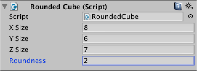
A vanilla cube is not that special. Let's turn it into a rounded cube! Rename the script file and the class name so it becomes RoundedCube. Unity should keep track of the component, but if the connection goes missing just drag the script onto it again.
We also need to control how much of the cube becomes rounded, so add a roundness field for that. It should be set to a value between one and half the smallest dimension of the cube.
public class RoundedCube : MonoBehaviour {

	public int xSize, ySize, zSize;
	public int roundness;

	…
}
While we could let Unity calculate the normals again, let's do it ourselves this time. As we'll compute the desired roundness of the cube instead of averaging adjacent triangles, our approach will be better. So add a normals array field.
Do normals manually this time.
	private Vector3[] normals;

	private void CreateVertices () {
		…
		vertices = new Vector3[cornerVertices + edgeVertices + faceVertices];
		normals = new Vector3[vertices.Length];

		…

		mesh.vertices = vertices;
		mesh.normals = normals;
	}
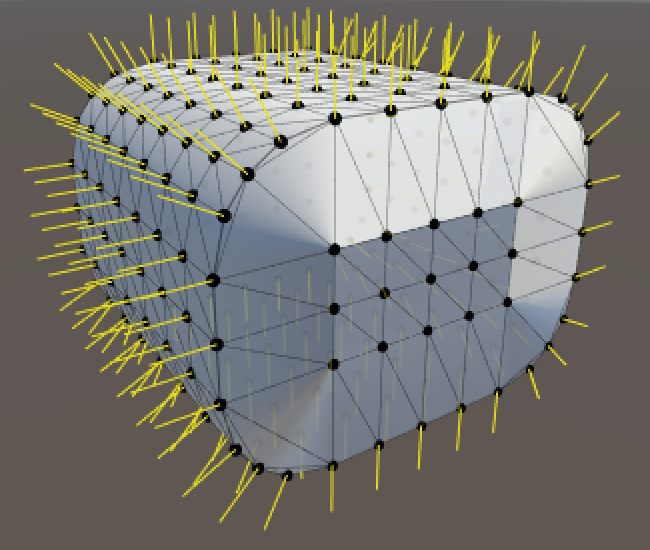
This allows use to draw gizmos for the normals as well, so we can verify that we do a good job.
	private void OnDrawGizmos () {
		if (vertices == null) {
			return;
		}
		for (int i = 0; i < vertices.Length; i++) {
			Gizmos.color = Color.black;
			Gizmos.DrawSphere(vertices[i], 0.1f);
			Gizmos.color = Color.yellow;
			Gizmos.DrawRay(vertices[i], normals[i]);
		}
	}
So how do we position the vertices of the rounded cubes and compute their normals? Let's invent a dedicated method for that.
	private void CreateVertices () {
		…

		int v = 0;
		for (int y = 0; y <= ySize; y++) {
			for (int x = 0; x <= xSize; x++) {
				SetVertex(v++, x, y, 0);
			}
			for (int z = 1; z <= zSize; z++) {
				SetVertex(v++, xSize, y, z);
			}
			for (int x = xSize - 1; x >= 0; x--) {
				SetVertex(v++, x, y, zSize);
			}
			for (int z = zSize - 1; z > 0; z--) {
				SetVertex(v++, 0, y, z);
			}
		}
		for (int z = 1; z < zSize; z++) {
			for (int x = 1; x < xSize; x++) {
				SetVertex(v++, x, ySize, z);
			}
		}
		for (int z = 1; z < zSize; z++) {
			for (int x = 1; x < xSize; x++) {
				SetVertex(v++, x, 0, z);
			}
		}

		mesh.vertices = vertices;
		mesh.normals = normals;
	}

	private void SetVertex (int i, int x, int y, int z) {
		vertices[i] = new Vector3(x, y, z);
	}
So how do we position the vertices? Consider a smaller cube floating inside our original cube. The distance between the faces of these two cubes is equal to the roundness. You could imagine spheres stuck on the corners of this smaller cube, their radius equal to the roundness, so the inner cube is firmly held in place.
For any point on the outer cube there's a point closest to it on the inner cube. We can use this to determine the normal vectors for the rounded cube.
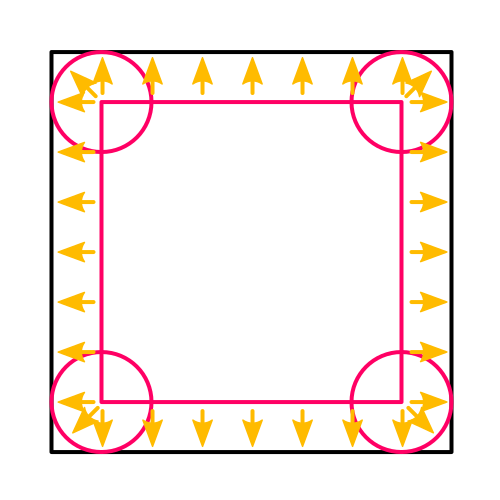
The surface points of the rounded cube can then be found by starting at the inner point and moving along the normal by an amount equal to the roundness. Here's the code to do that, except that it doesn't locate the inner point yet.
	private void SetVertex (int i, int x, int y, int z) {
		Vector3 inner = vertices[i] = new Vector3(x, y, z);

		normals[i] = (vertices[i] - inner).normalized;
		vertices[i] = inner + normals[i] * roundness;
	}
Now to find the inner point. Start by checking the X coordinate. If it's less than the roundness, then we're on the left of the inner cube and the inner X coordinate is simply the roundness value. And if we're beyond the X size of the cube minus the roundness, then we're on the right side. In all other cases we're in range of the inner cube and both points share the same X coordinate.
	private void SetVertex (int i, int x, int y, int z) {
		Vector3 inner = vertices[i] = new Vector3(x, y, z);

		if (x < roundness) {
			inner.x = roundness;
		}
		else if (x > xSize - roundness) {
			inner.x = xSize - roundness;
		}

		normals[i] = (vertices[i] - inner).normalized;
		vertices[i] = inner + normals[i] * roundness;
	}
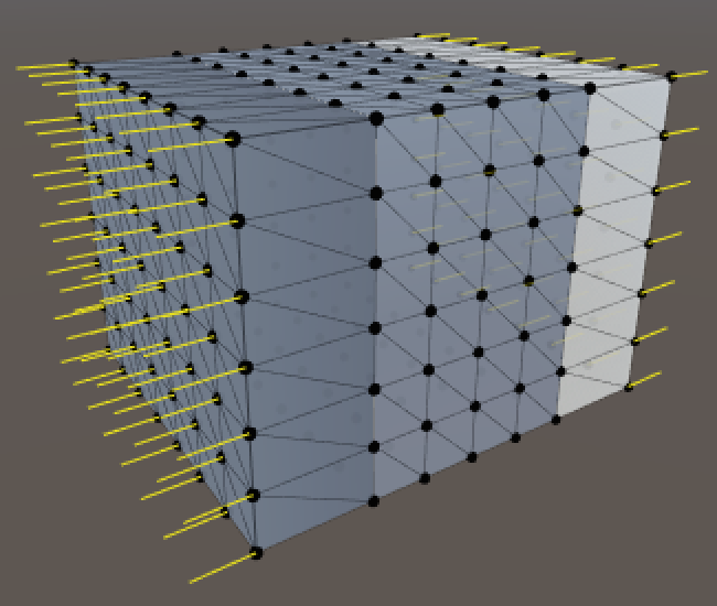
So far the result doesn't look rounded at all, but we are already getting normals in the positive and negative X directions. Throw in the same check for the Y coordinate.
		if (x < roundness) {
			inner.x = roundness;
		}
		else if (x > xSize - roundness) {
			inner.x = xSize - roundness;
		}
		if (y < roundness) {
			inner.y = roundness;
		}
		else if (y > ySize - roundness) {
			inner.y = ySize - roundness;
		}
It's starting to look better! The rounding and normals work in the XY plane. All that's left is to check the Z coordinate as well.
		if (x < roundness) {
			inner.x = roundness;
		}
		else if (x > xSize - roundness) {
			inner.x = xSize - roundness;
		}
		if (y < roundness) {
			inner.y = roundness;
		}
		else if (y > ySize - roundness) {
			inner.y = ySize - roundness;
		}
		if (z < roundness) {
			inner.z = roundness;
		}
		else if (z > zSize - roundness) {
			inner.z = zSize - roundness;
		}
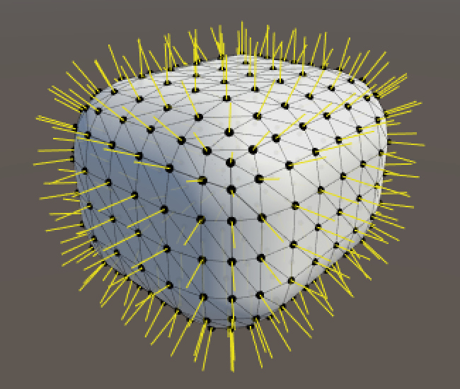
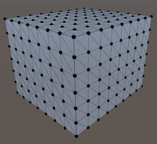
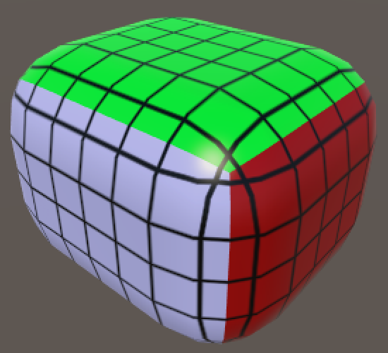
And we finally have a fully rounded cube.
unitypackageSplitting the Mesh
We have a nice rounded cube, created with a single mesh without any duplicate vertices. How do we texture this thing? We need UV coordinates for that, but there's no way to create a seamless wrapping. And seams require duplicate vertices…
We can switch to using duplicate vertices, but there is another way. We can use multiple sub-meshes to create separate triangle lists that use the same vertices. This allows us to use a different material for each set of triangles.
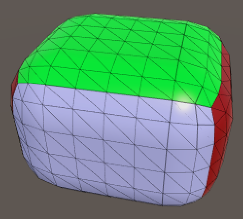
Let's split our mesh into three pairs of opposite face. This means that we'll need three array and three triangle indices.
	private void CreateTriangles () {
		int[] trianglesZ = new int[(xSize * ySize) * 12];
		int[] trianglesX = new int[(ySize * zSize) * 12];
		int[] trianglesY = new int[(xSize * zSize) * 12];
		int ring = (xSize + zSize) * 2;
		int tZ = 0, tX = 0, tY = 0, v = 0;

		…
	}
Now we have to split the ring loop into four segments, alternating between the arrays for Z and X.
		for (int y = 0; y < ySize; y++, v++) {
			for (int q = 0; q < xSize; q++, v++) {
				tZ = SetQuad(trianglesZ, tZ, v, v + 1, v + ring, v + ring + 1);
			}
			for (int q = 0; q < zSize; q++, v++) {
				tX = SetQuad(trianglesX, tX, v, v + 1, v + ring, v + ring + 1);
			}
			for (int q = 0; q < xSize; q++, v++) {
				tZ = SetQuad(trianglesZ, tZ, v, v + 1, v + ring, v + ring + 1);
			}
			for (int q = 0; q < zSize - 1; q++, v++) {
				tX = SetQuad(trianglesX, tX, v, v + 1, v + ring, v + ring + 1);
			}
			tX = SetQuad(trianglesX, tX, v, v - ring + 1, v + ring, v + 1);
		}
The top and bottom faces simply use the Y array.
		tY = CreateTopFace(trianglesY, tY, ring);
		tY = CreateBottomFace(trianglesY, tY, ring);
And instead of assigning to mesh.triangles we create three sub-meshes.
		mesh.subMeshCount = 3;
		mesh.SetTriangles(trianglesZ, 0);
		mesh.SetTriangles(trianglesX, 1);
		mesh.SetTriangles(trianglesY, 2);
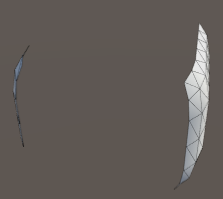
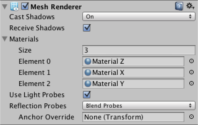
Our mesh is now cut into three pieces and only the first is actually rendered. We have to assign additional materials to the mesh renderer, one per sub-mesh. That's why there's a material array.
Rendering a Grid
While we can now differentiate faces, we still have no texture coordinates. Suppose we want to display a grid pattern across the entire cube, so that we can see the individual quads. How can we accomplish that?

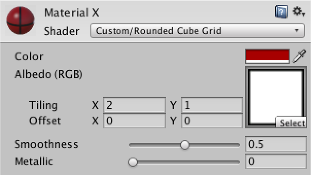
Instead of storing the UV coordinates in the mesh, maybe we can use a custom shader to figure out how to apply the texture. Here is a newly created shader.
Shader "Custom/Rounded Cube Grid" {
	Properties {
		_Color ("Color", Color) = (1,1,1,1)
		_MainTex ("Albedo (RGB)", 2D) = "white" {}
		_Glossiness ("Smoothness", Range(0,1)) = 0.5
		_Metallic ("Metallic", Range(0,1)) = 0.0
	}
	SubShader {
		Tags { "RenderType"="Opaque" }
		LOD 200

		CGPROGRAM
		#pragma surface surf Standard fullforwardshadows
		#pragma target 3.0

		sampler2D _MainTex;

		struct Input {
			float2 uv_MainTex;
		};

		half _Glossiness;
		half _Metallic;
		fixed4 _Color;

		void surf (Input IN, inout SurfaceOutputStandard o) {
			fixed4 c = tex2D(_MainTex, IN.uv_MainTex) * _Color;
			o.Albedo = c.rgb;
			o.Metallic = _Metallic;
			o.Smoothness = _Glossiness;
			o.Alpha = c.a;
		}
		ENDCG
	}
	FallBack "Diffuse"
}
This is a default surface shader. The important bit is that it defines an input structure which expects coordinates for the main texture. These coordinates are used in the surf function, which is invoked for each fragment that is rendered. As we don't have such coordinates, we have to replace uv_MainTex with something else.
		struct Input {
			float2 cubeUV;
		};

		…

		void surf (Input IN, inout SurfaceOutputStandard o) {
			fixed4 c = tex2D(_MainTex, IN.cubeUV) * _Color;
			o.Albedo = c.rgb;
			o.Metallic = _Metallic;
			o.Smoothness = _Glossiness;
			o.Alpha = c.a;
		}
As the UV are defined per vertex, we have to add a function that is invoked per vertex.
		CGPROGRAM
		#pragma surface surf Standard fullforwardshadows vertex:vert
		#pragma target 3.0

		sampler2D _MainTex;

		struct Input {
			float2 cubeUV;
		};

		half _Glossiness;
		half _Metallic;
		fixed4 _Color;

		void vert (inout appdata_full v, out Input o) {
			UNITY_INITIALIZE_OUTPUT(Input, o);
		}

		void surf (Input IN, inout SurfaceOutputStandard o) {
			fixed4 c = tex2D(_MainTex, IN.cubeUV) * _Color;
			o.Albedo = c.rgb;
			o.Metallic = _Metallic;
			o.Smoothness = _Glossiness;
			o.Alpha = c.a;
		}
		ENDCG
To check that our shader works, start with directly using the XY coordinates of the vertex position as UV.
		void vert (inout appdata_full v, out Input o) {
			UNITY_INITIALIZE_OUTPUT(Input, o);
			o.cubeUV = v.vertex.xy;
		}
This works reasonably for the Z faces, but the others are a mess. We need to use different vertex coordinates for them. So we have a choice to make, which we can support by adding a keyword enumeration shader property.
	Properties {
		_Color ("Color", Color) = (1,1,1,1)
		_MainTex ("Albedo (RGB)", 2D) = "white" {}
		_Glossiness ("Smoothness", Range(0,1)) = 0.5
		_Metallic ("Metallic", Range(0,1)) = 0.0
		[KeywordEnum(X, Y, Z)] _Faces ("Faces", Float) = 0
	}
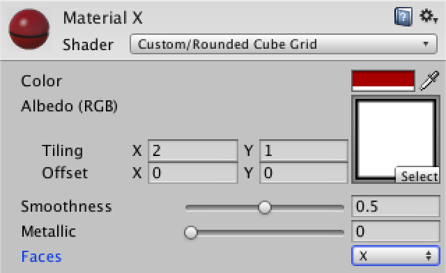
Depending on which option you select, Unity will enable a custom shader keyword for the material. We have to tell the shader to create versions of itself for each keyword that we wish to support.
	CGPROGRAM
		#pragma shader_feature _FACES_X _FACES_Y _FACES_Z
		#pragma surface surf Standard fullforwardshadows vertex:vert
		#pragma target 3.0
It is possible to check which keyword is defined, which enables us to write different code for each option.
		void vert (inout appdata_full v, out Input o) {
			UNITY_INITIALIZE_OUTPUT(Input, o);
			#if defined(_FACES_X)
				o.cubeUV = v.vertex.yz;
			#elif defined(_FACES_Y)
				o.cubeUV = v.vertex.xz;
			#elif defined(_FACES_Z)
				o.cubeUV = v.vertex.xy;
			#endif
		}
This is starting to look nice, but the grid lines don't fit the actual quads. Worse, as we're using the world-space vertex position things get weird when you move or rotate the cube.
We need the vertex positions of the original cube, before it was rounded. If we can store these in the mesh somehow we could pass them to the shader. As we're not using vertex colors, we can use the vertex color channel for this purpose.
	private Color32[] cubeUV;

	private void CreateVertices () {
		int cornerVertices = 8;
		int edgeVertices = (xSize + ySize + zSize - 3) * 4;
		int faceVertices = (
			(xSize - 1) * (ySize - 1) +
			(xSize - 1) * (zSize - 1) +
			(ySize - 1) * (zSize - 1)) * 2;
		vertices = new Vector3[cornerVertices + edgeVertices + faceVertices];
		normals = new Vector3[vertices.Length];
		cubeUV = new Color32[vertices.Length];

		…

		mesh.vertices = vertices;
		mesh.normals = normals;
		mesh.colors32 = cubeUV;
	}

	private void SetVertex (int i, int x, int y, int z) {
		…

		normals[i] = (vertices[i] - inner).normalized;
		vertices[i] = inner + normals[i] * roundness;
		cubeUV[i] = new Color32((byte)x, (byte)y, (byte)z, 0);
	}
We have to use Color32 instead of the usual Color type here, because vertex color components are stored as a single byte. An entire color is four bytes, the same size as a single float.
If we used regular colors, then Unity would convert from 0–1 floats to 0–255 bytes, truncating everything outside that range. By directly converting to bytes ourselves, we can deal with cube sizes up to 255, which should be enough.
On the shader side, we can now use the vertex color instead of its position. As the shader interprets vertex color channels as values in the 0–1 range, we have to undo this conversion by multiplying with 255.
		void vert (inout appdata_full v, out Input o) {
			UNITY_INITIALIZE_OUTPUT(Input, o);
			#if defined(_FACES_X)
				o.cubeUV = v.color.yz * 255;
			#elif defined(_FACES_Y)
				o.cubeUV = v.color.xz * 255;
			#elif defined(_FACES_Z)
				o.cubeUV = v.color.xy * 255;
			#endif
		}
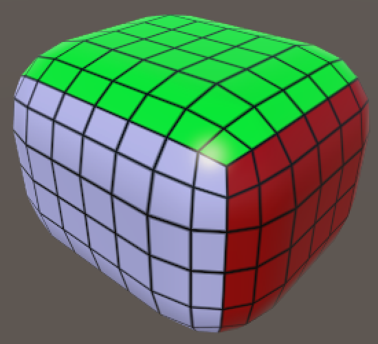
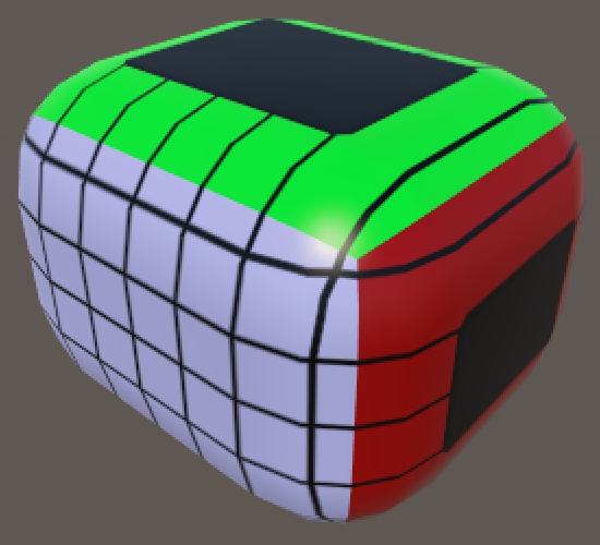
And we finally have a functional grid texture. Note that the UV coordinates of one of each pair of faces is mirrored, but this isn't a problem because we're using a symmetrical texture.
unitypackageAdding Colliders
Cubes are only fun when you can toss them around, which requires physics and colliders. Unfortunately mesh collider don't really work, because you'll quickly run into the polygon count limitation of convex colliders. But don't worry, we can use primitive colliders to create a perfect rounded cube. Let's add a method for that.
	private void Generate () {
		GetComponent<MeshFilter>().mesh = mesh = new Mesh();
		mesh.name = "Procedural Cube";
		CreateVertices();
		CreateTriangles();
		CreateColliders();
	}

	private void CreateColliders () {
	}
As a first step, add a single box collider.
	private void CreateColliders () {
		gameObject.AddComponent<BoxCollider>();
	}
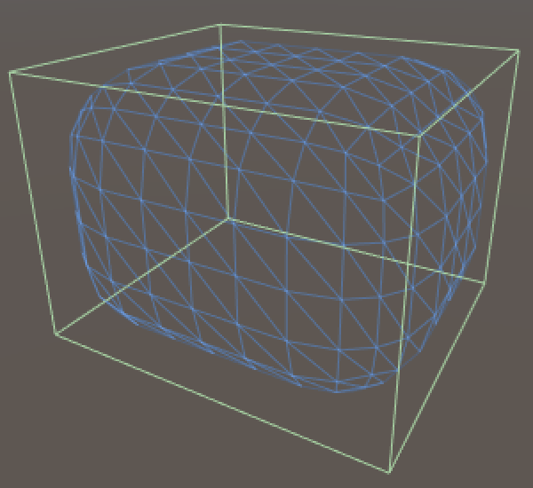
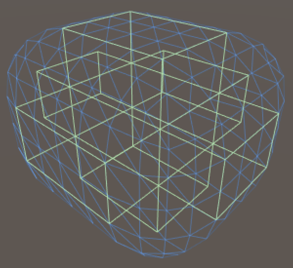
It turns out that Unity is smart enough to position and scale the collider such that it matches the bounding box of our mesh. Now we have to scale the collider so that it matches the flat sides of two opposite faces. As that needs to be done for all three face pairs, we end up with three intersecting blocks.
	private void CreateColliders () {
		AddBoxCollider(xSize, ySize - roundness * 2, zSize - roundness * 2);
		AddBoxCollider(xSize - roundness * 2, ySize, zSize - roundness * 2);
		AddBoxCollider(xSize - roundness * 2, ySize - roundness * 2, zSize);
	}

	private void AddBoxCollider (float x, float y, float z) {
		BoxCollider c = gameObject.AddComponent<BoxCollider>();
		c.size = new Vector3(x, y, z);
	}
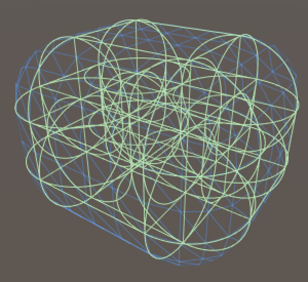
We can use capsules to fill the edges and corners. We need to give them the right orientation and position them at the center of each edge.
	private void AddCapsuleCollider (int direction, float x, float y, float z) {
		CapsuleCollider c = gameObject.AddComponent<CapsuleCollider>();
		c.center = new Vector3(x, y, z);
		c.direction = direction;
		c.radius = roundness;
		c.height = c.center[direction] * 2f;
	}
We need one capsule per edge, so twelve in total. I created min, half, and max vectors to make the placement easier.
private void CreateColliders () {
AddBoxCollider(xSize, ySize - roundness * 2, zSize - roundness * 2);
AddBoxCollider(xSize - roundness * 2, ySize, zSize - roundness * 2);
AddBoxCollider(xSize - roundness * 2, ySize - roundness * 2, zSize);
Vector3 min = Vector3.one * roundness;
Vector3 half = new Vector3(xSize, ySize, zSize) * 0.5f;
Vector3 max = new Vector3(xSize, ySize, zSize) - min;
AddCapsuleCollider(0, half.x, min.y, min.z);
AddCapsuleCollider(0, half.x, min.y, max.z);
AddCapsuleCollider(0, half.x, max.y, min.z);
AddCapsuleCollider(0, half.x, max.y, max.z);
AddCapsuleCollider(1, min.x, half.y, min.z);
AddCapsuleCollider(1, min.x, half.y, max.z);
AddCapsuleCollider(1, max.x, half.y, min.z);
AddCapsuleCollider(1, max.x, half.y, max.z);
AddCapsuleCollider(2, min.x, min.y, half.z);
AddCapsuleCollider(2, min.x, max.y, half.z);
AddCapsuleCollider(2, max.x, min.y, half.z);
AddCapsuleCollider(2, max.x, max.y, half.z);
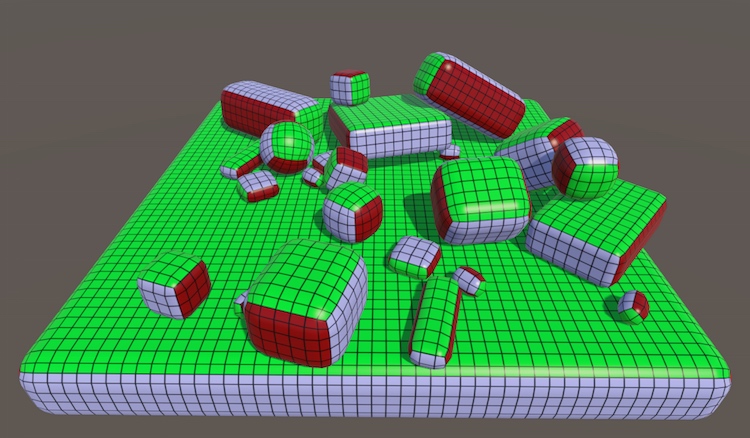
}
All that's left to do is add a rigidbody to the rounded cube, give it some friends, and go nuts! And once you're done with the cubes, have a look at the Cube Sphere tutorial.