Hex Map 10
Walls
- Wall off cells.
- Build walls along cell edges.
- Let rivers and roads go through.
- Avoid water and connect with cliffs.
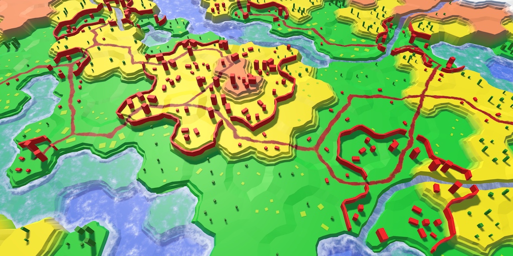
This tutorial is the tenth part of a series about hexagon maps. This time, we'll add walls in between cells.
Editing Walls
To support walls, we have to know where to place them. We'll put them in between cells, along the edges that connects them. As our already existing features are placed in the central area of cells, we don't need to worry about walls cutting through those features.
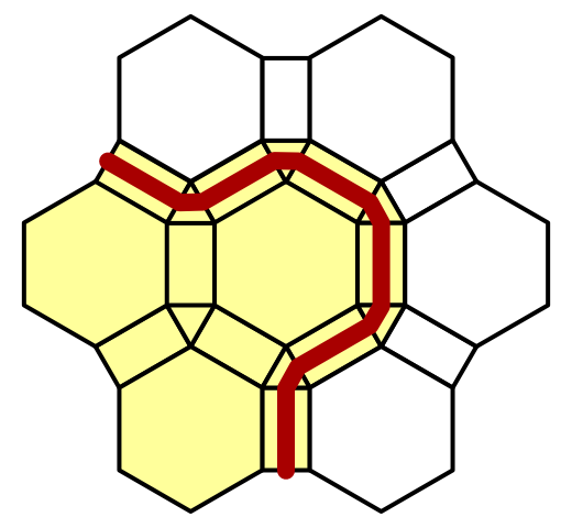
Walls are terrain features, although large ones. Like the other features, we don't edit them directly. Instead, we edit the cells. We're not going to place individual wall segments, we'll wall off entire cells.
Walled Property
To support walled cells, let's add a Walled property to HexCell. It's a simple toggle. Because the walls are placed in between cells, we have to refresh both the edited cell and its neighbors.
	public bool Walled {
		get {
			return walled;
		}
		set {
			if (walled != value) {
				walled = value;
				Refresh();
			}
		}
	}

	bool walled;
Editor Toggle
To adjust the walled state of cells, we have to add support for a toggle to HexMapEditor. So add another OptionalToggle field and a method to set it.
	OptionalToggle riverMode, roadMode, walledMode;

	…

	public void SetWalledMode (int mode) {
		walledMode = (OptionalToggle)mode;
	}
Unlike rivers and roads, walls don't go from cell to cell. They're in between them. So we don't need to worry about dragging. When the wall toggle is active, just set the the current cell's walled state based on the toggle.
	void EditCell (HexCell cell) {
		if (cell) {
			…
			if (roadMode == OptionalToggle.No) {
				cell.RemoveRoads();
			}
			if (walledMode != OptionalToggle.Ignore) {
				cell.Walled = walledMode == OptionalToggle.Yes;
			}
			if (isDrag) {
				…
			}
		}
	}
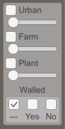
Duplicate one of the other toggle's UI elements and adjust them so they control the walled state. I put them in the UI panel with the other features.
Creating Walls
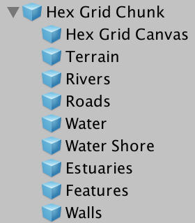
Because walls follow the contours of cells, they don't have a fixed shape. So we cannot simply use a prefab for them, like we do for the other features. Instead, we have to construct a mesh, as we do for the terrain. This means that our chunk prefab needs another HexMesh child. Duplicate one of its other mesh children, and make sure the new Walls objects cast shadows. It doesn't need anything besides vertices and triangles, so all HexMesh options should be disabled.
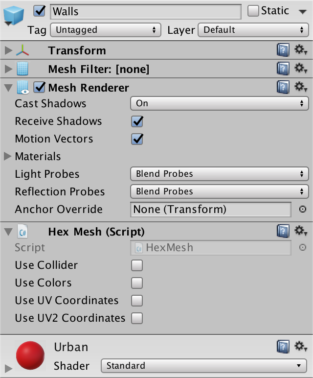
It makes sense that walls are an urban feature, so I used the red urban material for them.
Managing Walls
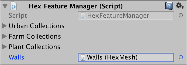
Because walls are features, they are the responsibility of HexFeatureManager. So give the feature manager a reference to the Walls object, and have it invoke the Clear and Apply methods.
	public HexMesh walls;

	…

	public void Clear () {
		…
		walls.Clear();
	}

	public void Apply () {
		walls.Apply();
	}
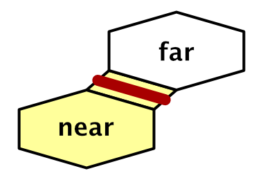
Now we have to add a method to the manager so walls can be added to it. As walls exists along the edges between cells, it needs to know the relevant edge vertices and cells. HexGridChunk will invoke it via TriangulateConnection, so with the cell currently being triangulated, and one of its neighbors. From this point of view, the current cell is on the near side of the wall, and the other cells is on the far side.
	public void AddWall (
		EdgeVertices near, HexCell nearCell,
		EdgeVertices far, HexCell farCell
	) {
	}
Invoke this new method in HexGridChunk.TriangulateConnection after all other connection work is done, right before we move on to the corner triangle. We'll leave it to the feature manager to decide whether a wall should actually be placed.
	void TriangulateConnection (
		HexDirection direction, HexCell cell, EdgeVertices e1
	) {
		…

		if (cell.GetEdgeType(direction) == HexEdgeType.Slope) {
			…
		}
		else {
			…
		}

		features.AddWall(e1, cell, e2, neighbor);

		HexCell nextNeighbor = cell.GetNeighbor(direction.Next());
		if (direction <= HexDirection.E && nextNeighbor != null) {
			…
		}
	}
Building a Wall Segment
An entire wall will snake through multiple cell edges. Each edge contains just a single segment of the wall. From the point of view of the near cell, the segment begins at the left side of the edge, and ends at the right side. Let's add a separate method to HexFeatureManager that creates a single segment, based on the four vertices at the corners of an edge.
	void AddWallSegment (
		Vector3 nearLeft, Vector3 farLeft, Vector3 nearRight, Vector3 farRight
	) {
	}
AddWall can invoke this method with the first and last vertices of the edges. But walls should only be added when we have a connection between a walled cell and one that is not walled. It doesn't matter which cell is on the inside or the outside, only that their state is different.
	public void AddWall (
		EdgeVertices near, HexCell nearCell,
		EdgeVertices far, HexCell farCell
	) {
		if (nearCell.Walled != farCell.Walled) {
			AddWallSegment(near.v1, far.v1, near.v5, far.v5);
		}
	}
The simplest possible wall segment is a single quad that stands in the middle of the edge. We find its bottom vertices by interpolating halfway from the near to the far vertices.
	void AddWallSegment (
		Vector3 nearLeft, Vector3 farLeft, Vector3 nearRight, Vector3 farRight
	) {
		Vector3 left = Vector3.Lerp(nearLeft, farLeft, 0.5f);
		Vector3 right = Vector3.Lerp(nearRight, farRight, 0.5f);
	}
How high should our walls be? Let's define this in HexMetrics. I made them as high as a single elevation level.
public const float wallHeight = 3f;
HexFeatureManager.AddWallSegment can use this height to position the third and fourth vertices of our quad, and add it to the walls mesh.
		Vector3 left = Vector3.Lerp(nearLeft, farLeft, 0.5f);
		Vector3 right = Vector3.Lerp(nearRight, farRight, 0.5f);

		Vector3 v1, v2, v3, v4;
		v1 = v3 = left;
		v2 = v4 = right;
		v3.y = v4.y = left.y + HexMetrics.wallHeight;
		walls.AddQuad(v1, v2, v3, v4);
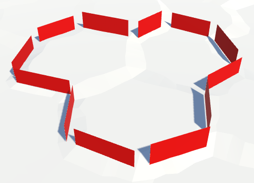
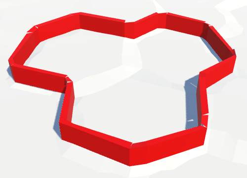
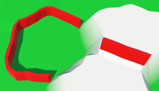
You can now edit walls and they will show up as strips of quads. However, you won't see an unbroken wall. Each quad is only visible from one side. Its face is oriented towards the cell it was added from.

We can quickly solve this by adding a second quad that's facing the other side.
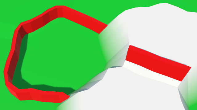
		walls.AddQuad(v1, v2, v3, v4);
		walls.AddQuad(v2, v1, v4, v3);
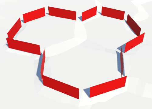
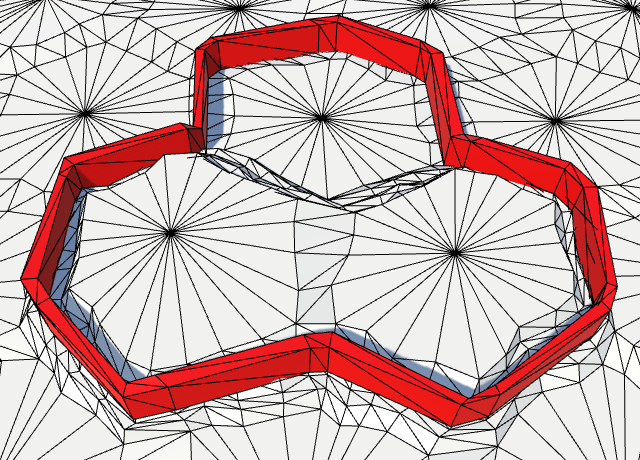
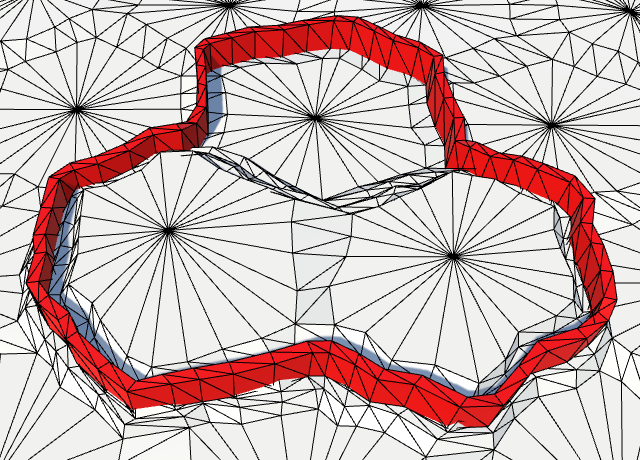
The entire walls are now visible, although there are still gaps at the cell corners, where three cells meet. We'll fill those later.
Thick Walls
Although the walls are visible from both sides, they don't have any thickness. The walls are effectively as thin as paper, making them nearly invisible from certain view angles. So let's make them solid by adding thickness. Let's define how thick they are in HexMetrics. I picked 0.75 units as an arbitrary value that looked good to me.
public const float wallThickness = 0.75f;
To make the walls thick, we have to pull the two quads apart. They have to move in opposite directions. One side should move towards the near edge, the other towards the far edge. The offset vector to do this is simply far - near, but to keep the top of the wall flat, we should set its Y component to zero.
Because we have to do this for both the left and right part of the wall segment, let's add a method to HexMetrics to compute this offset vector.
	public static Vector3 WallThicknessOffset (Vector3 near, Vector3 far) {
		Vector3 offset;
		offset.x = far.x - near.x;
		offset.y = 0f;
		offset.z = far.z - near.z;
		return offset;
	}
To keep the wall at the center of the edge, the actual distance to move along this vector is equal to half the thickness per side. And to make sure we indeed move the desired distance, normalize the offset vector before scaling it.
return offset.normalized * (wallThickness * 0.5f);
Use this method in HexFeatureManager.AddWallSegment to adjust the position of the quads. As the offset vector goes from near to far, subtract it from the near quad, and add it to the far quad.
		Vector3 left = Vector3.Lerp(nearLeft, farLeft, 0.5f);
		Vector3 right = Vector3.Lerp(nearRight, farRight, 0.5f);

		Vector3 leftThicknessOffset =
			HexMetrics.WallThicknessOffset(nearLeft, farLeft);
		Vector3 rightThicknessOffset =
			HexMetrics.WallThicknessOffset(nearRight, farRight);

		Vector3 v1, v2, v3, v4;
		v1 = v3 = left - leftThicknessOffset;
		v2 = v4 = right - rightThicknessOffset;
		v3.y = v4.y = left.y + HexMetrics.wallHeight;
		walls.AddQuad(v1, v2, v3, v4);

		v1 = v3 = left + leftThicknessOffset;
		v2 = v4 = right + rightThicknessOffset;
		v3.y = v4.y = left.y + HexMetrics.wallHeight;
		walls.AddQuad(v2, v1, v4, v3);
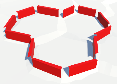
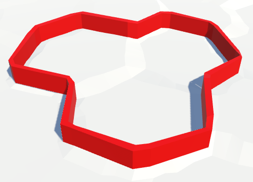
The quads are now offset, although it isn't that obvious. The shadows give it away.
Wall Tops
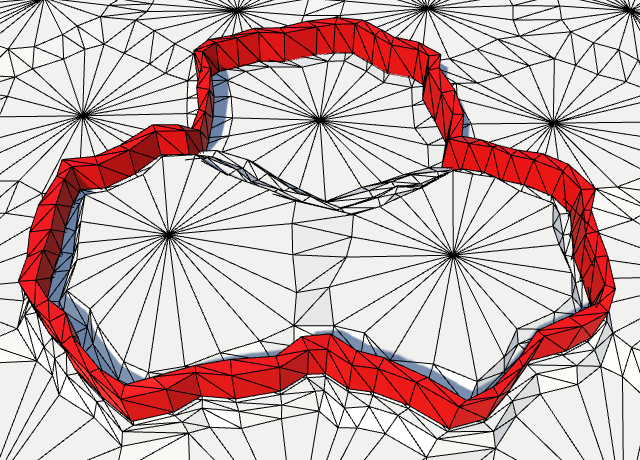
To made the thickness of the walls visible from above, we have to add a quad on top of the wall. A simple way to add it is to remember the top two vertices of the first quad, and connect them with the top two of the second quad.
		Vector3 v1, v2, v3, v4;
		v1 = v3 = left - leftThicknessOffset;
		v2 = v4 = right - rightThicknessOffset;
		v3.y = v4.y = left.y + HexMetrics.wallHeight;
		walls.AddQuad(v1, v2, v3, v4);

		Vector3 t1 = v3, t2 = v4;

		v1 = v3 = left + leftThicknessOffset;
		v2 = v4 = right + rightThicknessOffset;
		v3.y = v4.y = left.y + HexMetrics.wallHeight;
		walls.AddQuad(v2, v1, v4, v3);

		walls.AddQuad(t1, t2, v3, v4);
Turning Corners
The remaining gaps are those at the corners of cells. To fill those, we have to add a segment in the triangular area between the cells. Each corner connects three cells. Each cell can be either walled or not. So there are eight possible configurations.
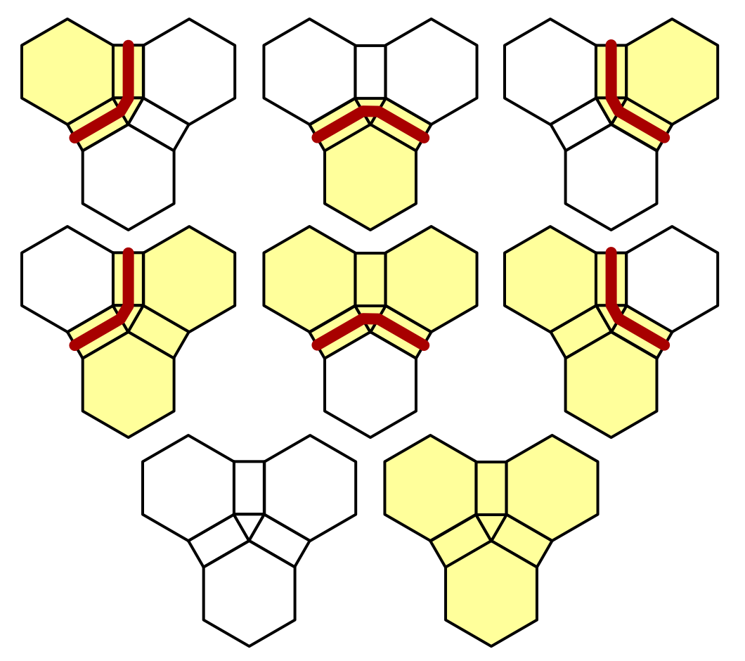
We only place walls in between cells with different walled states. That reduces the number of relevant configurations to six. In each of those, one of the cells lies on the inside of the wall curve. Let's consider this cell the pivot around which the wall curves. From the point of view of this cell, the wall starts at the edge shared with the left cell and ends at the edge shared with the right cell.
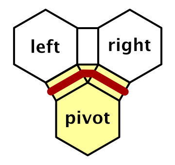
So we have to create an AddWallSegment method which has the three corner vertices as parameters. While we could write the code to triangulate this segment, it's actually a special case of the other AddWallSegment method. The pivot plays the role of both near vertices.
	void AddWallSegment (
		Vector3 pivot, HexCell pivotCell,
		Vector3 left, HexCell leftCell,
		Vector3 right, HexCell rightCell
	) {
		AddWallSegment(pivot, left, pivot, right);
	}
Next, create an AddWall method variant for three corner vertices and their cells. The job of this method is to figure out which corner is the pivot, if there is one. So it has to account for all eight possible configurations, and invoke AddWallSegment for six of them.
	public void AddWall (
		Vector3 c1, HexCell cell1,
		Vector3 c2, HexCell cell2,
		Vector3 c3, HexCell cell3
	) {
		if (cell1.Walled) {
			if (cell2.Walled) {
				if (!cell3.Walled) {
					AddWallSegment(c3, cell3, c1, cell1, c2, cell2);
				}
			}
			else if (cell3.Walled) {
				AddWallSegment(c2, cell2, c3, cell3, c1, cell1);
			}
			else {
				AddWallSegment(c1, cell1, c2, cell2, c3, cell3);
			}
		}
		else if (cell2.Walled) {
			if (cell3.Walled) {
				AddWallSegment(c1, cell1, c2, cell2, c3, cell3);
			}
			else {
				AddWallSegment(c2, cell2, c3, cell3, c1, cell1);
			}
		}
		else if (cell3.Walled) {
			AddWallSegment(c3, cell3, c1, cell1, c2, cell2);
		}
	}
To add the corner segments, invoke this method at the end of HexGridChunk.TriangulateCorner.
	void TriangulateCorner (
		Vector3 bottom, HexCell bottomCell,
		Vector3 left, HexCell leftCell,
		Vector3 right, HexCell rightCell
	) {
		…

		features.AddWall(bottom, bottomCell, left, leftCell, right, rightCell);
	}
Closing the Gaps
There are still gaps in the walls, because the elevation of the wall segments is inconsistent. While segments along edges have constant elevation, corner segments sit between two different edges. As each edge can have a different elevation, gaps appear at the corners.
To fix this, adjust AddWallSegment so it keeps the Y coordinates of the left and right top vertices separate.
		float leftTop = left.y + HexMetrics.wallHeight;
		float rightTop = right.y + HexMetrics.wallHeight;

		Vector3 v1, v2, v3, v4;
		v1 = v3 = left - leftThicknessOffset;
		v2 = v4 = right - rightThicknessOffset;
		v3.y = leftTop;
		v4.y = rightTop;
		walls.AddQuad(v1, v2, v3, v4);

		Vector3 t1 = v3, t2 = v4;

		v1 = v3 = left + leftThicknessOffset;
		v2 = v4 = right + rightThicknessOffset;
		v3.y = leftTop;
		v4.y = rightTop;
		walls.AddQuad(v2, v1, v4, v3);
The walls are now closed, but it is likely that you still see gaps in the wall's shadows. This is causes by the Normal Bias of the directional light's shadow settings. When larger than zero, the triangles of shadow casters are pushed along the surface normal. This prevents self-shadowing, but also creates gaps where triangles face away from each other. This can produce visible gaps in the shadows of thin geometry, like our walls.
You can get rid of these shadow artifacts by reducing the normal bias to zero. Alternatively, change the Cast Shadows mode of the wall's mesh renderer to Two Sided. That forces the shadow caster pass to render both sides of each wall triangle, which covers up the holes.

Walls on Terraces
Currently, our walls are rather straight. This isn't so bad on flat terrain, but it looks weird when walls coincide with terraces. This happens when there is a one-level elevation difference between cells on opposite sides of a wall.
Following the Edge
Instead of creating a single segment for an entire edge, let's create one for each part of an edge strip. We can do this by invoking AddWallSegment four times in the AddWall version for edges.
	public void AddWall (
		EdgeVertices near, HexCell nearCell,
		EdgeVertices far, HexCell farCell
	) {
		if (nearCell.Walled != farCell.Walled) {
			AddWallSegment(near.v1, far.v1, near.v2, far.v2);
			AddWallSegment(near.v2, far.v2, near.v3, far.v3);
			AddWallSegment(near.v3, far.v3, near.v4, far.v4);
			AddWallSegment(near.v4, far.v4, near.v5, far.v5);
		}
	}
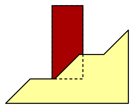
The walls now follow the shape of the perturbed edges. This looks much better in combination with terraces. It also produces more interesting walls on flat terrain.
Placing Walls on the Ground
When taking a closer look at walls on terraces, we find that there is a problem. The walls end up floating above the ground! This is true for slanted flat edges as well, but that's usually not as noticeable.
To solve this, we have to lower the walls. Simplest is just to lower the entire wall, so its top remains flat. This will cause part of the wall on the higher side to sink into the terrain, which is fine.
To lower the wall, we first have to determine which side is lowest, the near or the far side. We could just use the elevation of the lowest side, but we don't need to go that low. We can interpolate from the low to the high Y coordinate with an offset that's somewhere below 0.5. As our walls only rarely extend beyond the lowest terrace step, we can use the vertical terrace step size as our offset. A different wall thickness of terrace configuration might require another offset.
Let's add a WallLerp method to HexMetrics which takes care of this interpolation, in addition to averaging the X and Z coordinates of the near and far vertices. It's based on the TerraceLerp method.
	public const float wallElevationOffset = verticalTerraceStepSize;

	…

	public static Vector3 WallLerp (Vector3 near, Vector3 far) {
		near.x += (far.x - near.x) * 0.5f;
		near.z += (far.z - near.z) * 0.5f;
		float v =
			near.y < far.y ? wallElevationOffset : (1f - wallElevationOffset);
		near.y += (far.y - near.y) * v;
		return near;
	}
Have HexFeatureManager use this method to determine the left and right vertices.
	void AddWallSegment (
		Vector3 nearLeft, Vector3 farLeft, Vector3 nearRight, Vector3 farRight
	) {
		Vector3 left = HexMetrics.WallLerp(nearLeft, farLeft);
		Vector3 right = HexMetrics.WallLerp(nearRight, farRight);

		…
	}
Adjusting Wall Perturbation
Our walls now play nice with elevation differences. But they still don't exactly match the perturbed edges, although it is close. That's because we first figure out the wall vertices, and then perturb them. As these vertices sit somewhere in between the near and far edge vertices, their perturbation will be slightly different.
That the walls don't exactly follow the edges isn't a problem. However, perturbing the wall's vertices disturbs its otherwise relatively uniform thickness. If we position the walls using perturbed vertices, and then add unperturbed quads, its thickness shouldn't vary as much.
	void AddWallSegment (
		Vector3 nearLeft, Vector3 farLeft, Vector3 nearRight, Vector3 farRight
	) {
		nearLeft = HexMetrics.Perturb(nearLeft);
		farLeft = HexMetrics.Perturb(farLeft);
		nearRight = HexMetrics.Perturb(nearRight);
		farRight = HexMetrics.Perturb(farRight);

		…
		walls.AddQuadUnperturbed(v1, v2, v3, v4);

		…
		walls.AddQuadUnperturbed(v2, v1, v4, v3);

		walls.AddQuadUnperturbed(t1, t2, v3, v4);
	}
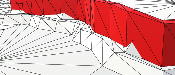
Using this approach, our walls no longer follow the edges as close as they did. But in return, they're less jagged and have much more consistent thickness.
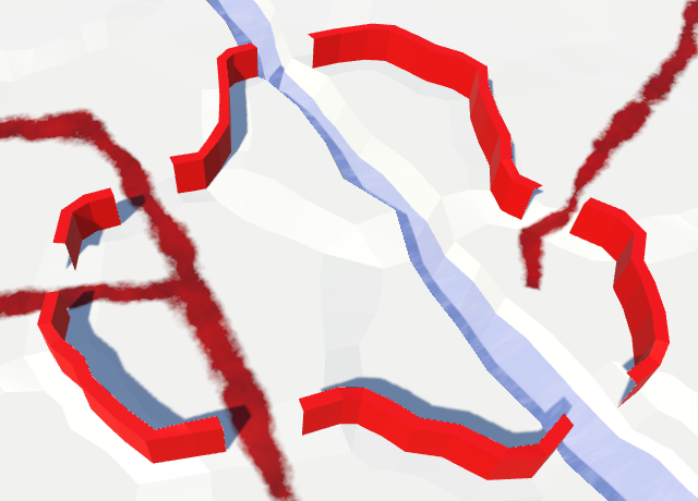
Wall Openings
Up to this point, we have ignored the possibility that a river or road might cross a wall. When that happens, we should make a gap in the wall, so the river or road can pass through.
To support this, add two boolean parameters to AddWall to indicate whether there's a river or road going through the edge. While we could treat them differently, let's just remove the middle two segments in both cases.
	public void AddWall (
		EdgeVertices near, HexCell nearCell,
		EdgeVertices far, HexCell farCell,
		bool hasRiver, bool hasRoad
	) {
		if (nearCell.Walled != farCell.Walled) {
			AddWallSegment(near.v1, far.v1, near.v2, far.v2);
			if (hasRiver || hasRoad) {
				// Leave a gap.
			}
			else {
				AddWallSegment(near.v2, far.v2, near.v3, far.v3);
				AddWallSegment(near.v3, far.v3, near.v4, far.v4);
			}
			AddWallSegment(near.v4, far.v4, near.v5, far.v5);
		}
	}
Now HexGridChunk.TriangulateConnection has to provide the necessary data. Because it already needed the same information earlier, let's cache it in boolean variables and write the relevant method invocations only once.
	void TriangulateConnection (
		HexDirection direction, HexCell cell, EdgeVertices e1
	) {
		…

		bool hasRiver = cell.HasRiverThroughEdge(direction);
		bool hasRoad = cell.HasRoadThroughEdge(direction);

		if (hasRiver) {
			…
		}

		if (cell.GetEdgeType(direction) == HexEdgeType.Slope) {
			TriangulateEdgeTerraces(e1, cell, e2, neighbor, hasRoad);
		}
		else {
			TriangulateEdgeStrip(e1, cell.Color, e2, neighbor.Color, hasRoad);
		}

		features.AddWall(e1, cell, e2, neighbor, hasRiver, hasRoad);
		…
	}
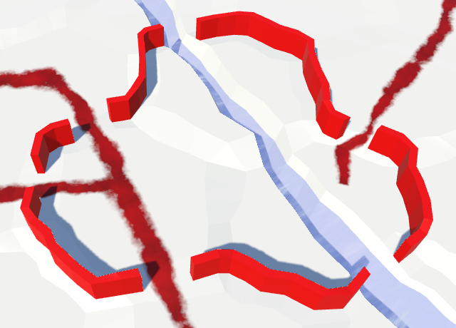
Capping the Walls
The new gaps have introduced places where the walls end. We have to cap these endpoints with quads, so we don't end up looking through the sides of the wall. Create an AddWallCap method in HexFeatureManager for this purpose. It works like AddWallSegment, except that it needs only one pair of near–far vertices. Have it add a quad that goes from the near to the far side of the wall.
	void AddWallCap (Vector3 near, Vector3 far) {
		near = HexMetrics.Perturb(near);
		far = HexMetrics.Perturb(far);

		Vector3 center = HexMetrics.WallLerp(near, far);
		Vector3 thickness = HexMetrics.WallThicknessOffset(near, far);

		Vector3 v1, v2, v3, v4;

		v1 = v3 = center - thickness;
		v2 = v4 = center + thickness;
		v3.y = v4.y = center.y + HexMetrics.wallHeight;
		walls.AddQuadUnperturbed(v1, v2, v3, v4);
	}
When AddWall determines that we need a gap, add a cap between the second and fourth edge vertex pairs. We have to switch orientation for the fourth vertex pair, otherwise that quad would end up facing inwards.
	public void AddWall (
		EdgeVertices near, HexCell nearCell,
		EdgeVertices far, HexCell farCell,
		bool hasRiver, bool hasRoad
	) {
		if (nearCell.Walled != farCell.Walled) {
			AddWallSegment(near.v1, far.v1, near.v2, far.v2);
			if (hasRiver || hasRoad) {
				AddWallCap(near.v2, far.v2);
				AddWallCap(far.v4, near.v4);
			}
			…
		}
	}
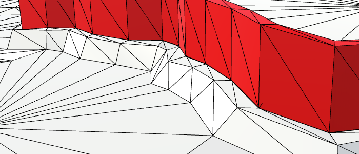
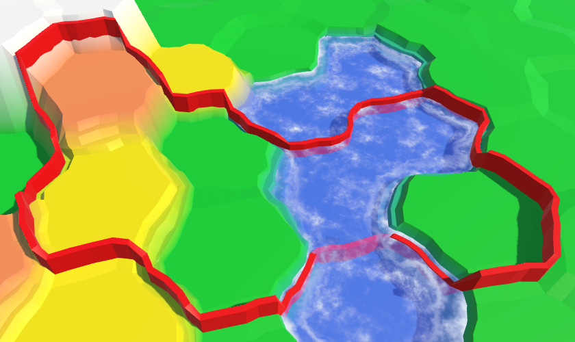
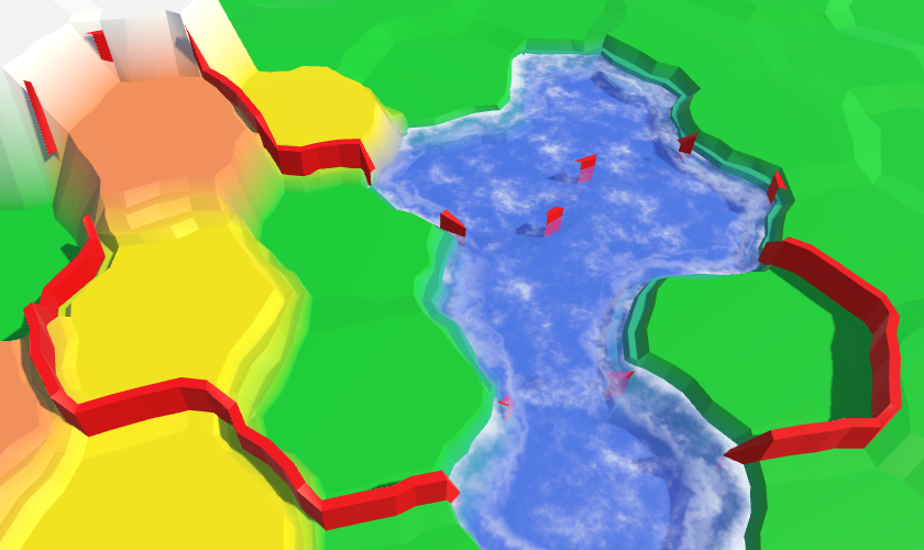
Avoiding Cliffs and Water
Finally, let's consider edges that contain cliffs or water. Because cliffs are effectively huge walls, it makes little sense to place an additional wall halfway up them. And it looks bad. Also, underwater walls make little sense. Walling off the coastline doesn't look good either.
We can eliminate walls from these inappropriate edges with additional checks in AddWall. Neither cell can be underwater, and their shared edge cannot be a cliff.
	public void AddWall (
		EdgeVertices near, HexCell nearCell,
		EdgeVertices far, HexCell farCell,
		bool hasRiver, bool hasRoad
	) {
		if (
			nearCell.Walled != farCell.Walled &&
			!nearCell.IsUnderwater && !farCell.IsUnderwater &&
			nearCell.GetEdgeType(farCell) != HexEdgeType.Cliff
		) {
			…
		}
	}
Removing Wall Corners
Eliminating unwanted corner segments requires a little more work. The easiest case to avoid is when the pivot cell is underwater. That guarantees there aren't any adjacent wall segments to connect.
	void AddWallSegment (
		Vector3 pivot, HexCell pivotCell,
		Vector3 left, HexCell leftCell,
		Vector3 right, HexCell rightCell
	) {
		if (pivotCell.IsUnderwater) {
			return;
		}

		AddWallSegment(pivot, left, pivot, right);
	}
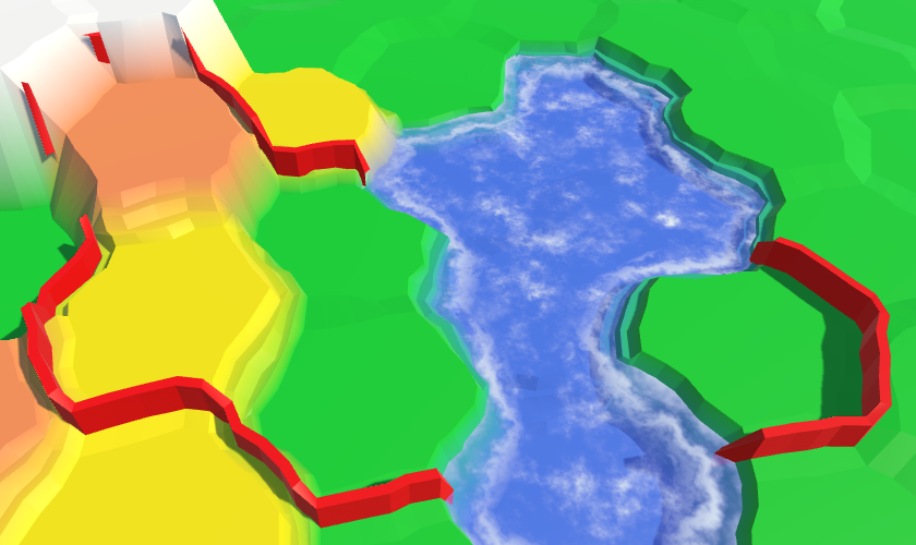
Now we have to look at the other two cells. If one of them is underwater, or is connected to the pivot via a cliff, then there is no wall along that edge. If this is true for at least one side, then there shouldn't be a wall segment in this corner.
Determine whether there's a left or right wall independently. Put the results in boolean variables, so they're easier to reason with.
		if (pivotCell.IsUnderwater) {
			return;
		}

		bool hasLeftWall = !leftCell.IsUnderwater &&
			pivotCell.GetEdgeType(leftCell) != HexEdgeType.Cliff;
		bool hasRighWall = !rightCell.IsUnderwater &&
			pivotCell.GetEdgeType(rightCell) != HexEdgeType.Cliff;

		if (hasLeftWall && hasRighWall) {
			AddWallSegment(pivot, left, pivot, right);
		}
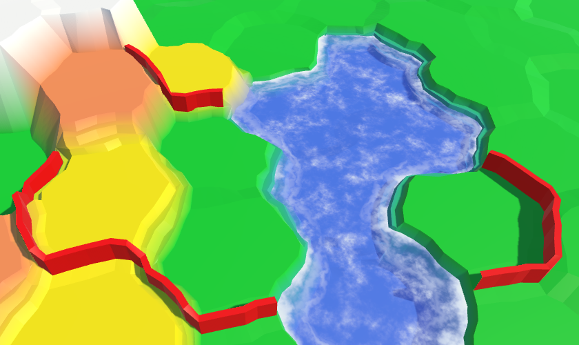
Capping Corners
When both the left and the right edge don't have a wall, we're done. But when there's a wall in just one direction, it means that we have another gap in the wall. So we must cap it.
		if (hasLeftWall) {
			if (hasRighWall) {
				AddWallSegment(pivot, left, pivot, right);
			}
			else {
				AddWallCap(pivot, left);
			}
		}
		else if (hasRighWall) {
			AddWallCap(right, pivot);
		}
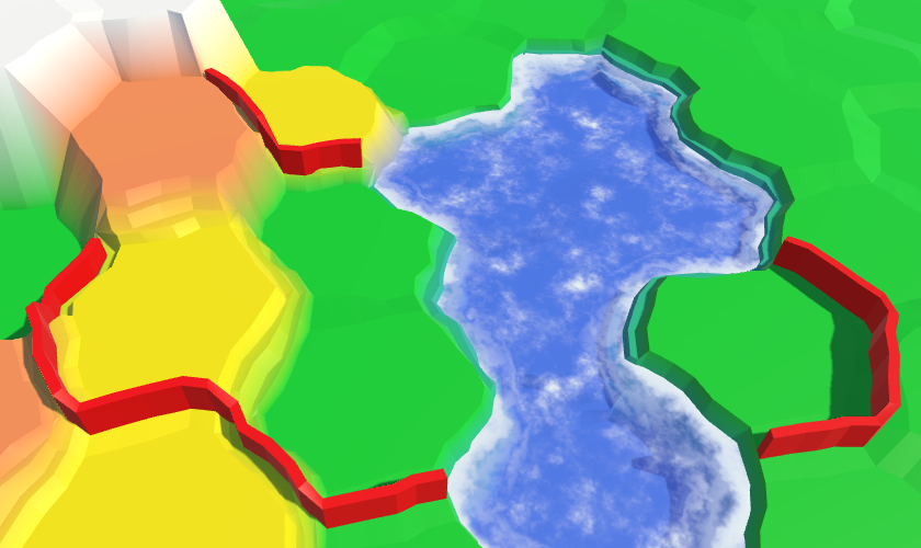
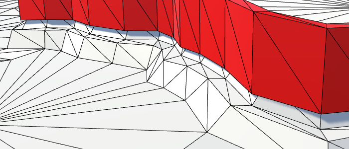
Fusing Walls with Cliffs
There is one situation in which our walls look less than ideal. When a wall reaches the bottom of a cliff, it ends. Because cliffs aren't perfectly vertical, this leaves a narrow gap between the wall and the cliff face. This problem doesn exist at the top of a cliff.
It would be much nicer if a wall continued all the way to the cliff face, leaving no gap. We can do this by adding an extra wall segment between the current end of the wall and the cliff's corner vertex. Because a large part of this segment ends up hidden inside the cliff, we can get away with reducing the wall thickness to zero inside the cliff. Thus, we only need to create a wedge shape. Two quads coming to a point, and a triangle on top. Create an AddWallWedge method for this purpose. You can do so by copying AddWallCap and adding the wedge's point. I've marked the differences.
	void AddWallWedge (Vector3 near, Vector3 far, Vector3 point) {
		near = HexMetrics.Perturb(near);
		far = HexMetrics.Perturb(far);
		point = HexMetrics.Perturb(point);

		Vector3 center = HexMetrics.WallLerp(near, far);
		Vector3 thickness = HexMetrics.WallThicknessOffset(near, far);

		Vector3 v1, v2, v3, v4;
		Vector3 pointTop = point;
		point.y = center.y;

		v1 = v3 = center - thickness;
		v2 = v4 = center + thickness;
		v3.y = v4.y = pointTop.y = center.y + HexMetrics.wallHeight;

//		walls.AddQuadUnperturbed(v1, v2, v3, v4);
		walls.AddQuadUnperturbed(v1, point, v3, pointTop);
		walls.AddQuadUnperturbed(point, v2, pointTop, v4);
		walls.AddTriangleUnperturbed(pointTop, v3, v4);
	}
In AddWallSegment for corners, invoke this method when there's a wall in only one direction, and that wall is at a lower elevation than the other side. That's when we're running into a cliff face.
		if (hasLeftWall) {
			if (hasRighWall) {
				AddWallSegment(pivot, left, pivot, right);
			}
			else if (leftCell.Elevation < rightCell.Elevation) {
				AddWallWedge(pivot, left, right);
			}
			else {
				AddWallCap(pivot, left);
			}
		}
		else if (hasRighWall) {
			if (rightCell.Elevation < leftCell.Elevation) {
				AddWallWedge(right, pivot, left);
			}
			else {
				AddWallCap(right, pivot);
			}
		}
The next tutorial is More Features.