Hex Map 14
Terrain Textures
- Use vertex colors to design a splat map.
- Create a texture array asset.
- Add terrain indices to meshes.
- Blend between terrain textures.
This is part 14 of a tutorial series about hexagon maps. Up to this point, we've used solid colors to paint our maps. Now we're going to use textures instead.
Blending Three Types
While uniform colors are clear and get the job done, they're not very interesting to look at. Upgrading to textures can greatly increase the appeal of our maps. Of course, that requires that we blend textures, instead of just colors. The Rendering 3, Combining Textures tutorial shows how you can blend multiple textures, by using a splat map. We can use a similar approach for our hex maps.
The Rendering 3 tutorial only blends four textures, and could support up to five with a single splat map. We currently use five different colors, so that could work. However, we might want to add more types later. So we should support an arbitrary amount of terrain types. This isn't possible with explicit texture properties. Instead, we have to use a texture array. We'll create one later.
When using texture arrays, we have to somehow tell the shader which textures to blend. The most complex blend is required for corner triangles, which can sit between three cells that each have a different terrain type. So we have to support blending between three different types per triangle.
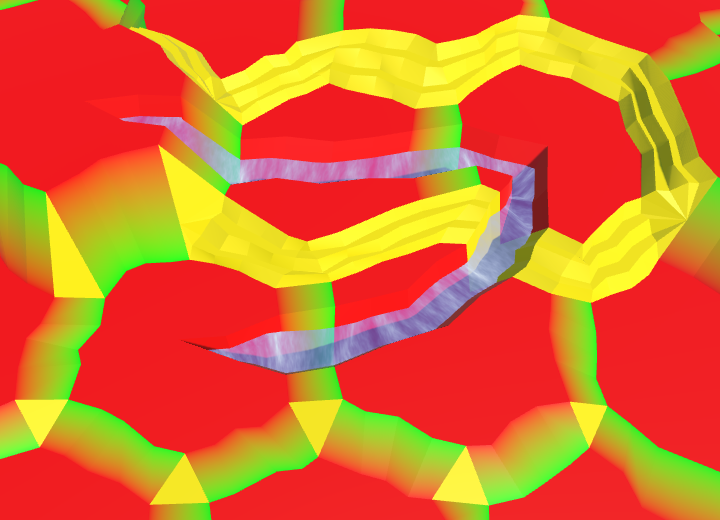
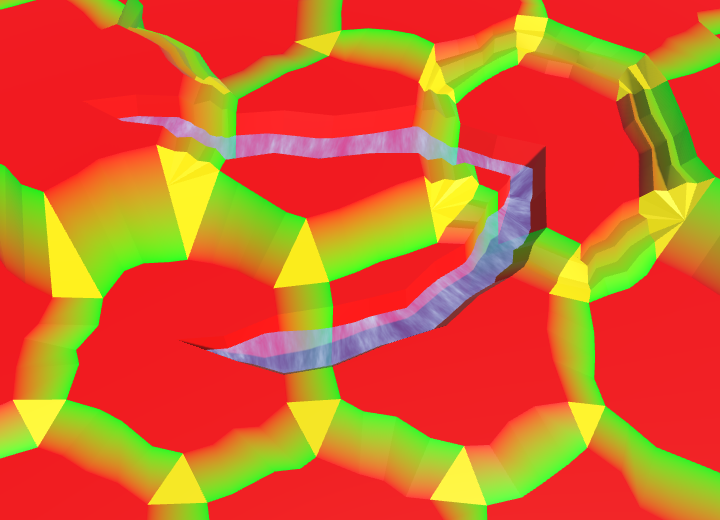
Using Vertex Colors as Splat Maps
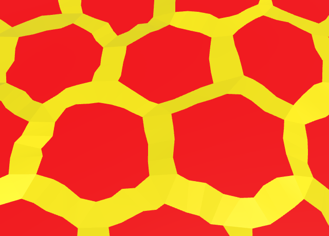
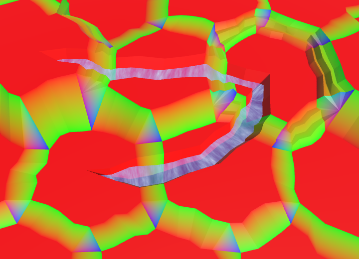
Assuming we can communicate which textures to blend, we can use vertex colors to create a splat map for each triangle. As there are at most three textures in play at a time, we only need three color channels. Red represents the first texture, green corresponds with the second, and blue is for the third.

If a triangle requires only a single texture, we'll just use the first channel. So its color will be solid red. In the case of a blend between two different types, we'll use both the first and second channel. So that triangle's color will be a blend between red and green. And if all three types are in play, it's a blend between red, green, and blue.

We'll use these splat map configurations no matter which textures are actually blended. So the splat map is always the same. It's the textures that vary. We'll figure out how to do that later.
We have to update HexGridChunk so it creates these splat maps, instead of using the cell colors. Because we'll be using the three colors a lot, create static fields for them.
	static Color color1 = new Color(1f, 0f, 0f);
	static Color color2 = new Color(0f, 1f, 0f);
	static Color color3 = new Color(0f, 0f, 1f);
Cell Centers
Start by replacing the color of the default cell centers. There is no blend going on here, so we simply use the first color, which is red.
	void TriangulateWithoutRiver (
		HexDirection direction, HexCell cell, Vector3 center, EdgeVertices e
	) {
		TriangulateEdgeFan(center, e, color1);

		…
	}
The cell centers have now become red. They all use the first of the three textures, no matter which texture that happens to be. Their splat maps are identical, no matter which color you paint the cells.
Adjacent to Rivers
We've only changed segments inside cells without rivers flowing through them. We have to do the same for segments that are adjacent to rivers. In this case, it's both an edge strip and an edge fan. Again, red is all we need.
	void TriangulateAdjacentToRiver (
		HexDirection direction, HexCell cell, Vector3 center, EdgeVertices e
	) {
		…

		TriangulateEdgeStrip(m, color1, e, color1);
		TriangulateEdgeFan(center, m, color1);

		…
	}
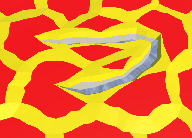
Rivers
Next, we have to take care of the river geometry inside the cells. They should all become red too. First, the parts at the beginning and end of rivers.
	void TriangulateWithRiverBeginOrEnd (
		HexDirection direction, HexCell cell, Vector3 center, EdgeVertices e
	) {
		…

		TriangulateEdgeStrip(m, color1, e, color1);
		TriangulateEdgeFan(center, m, color1);

		…
	}
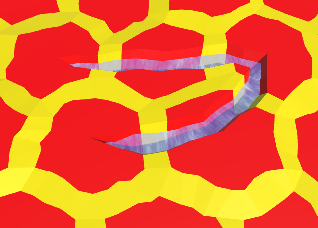
And then the geometry that makes up the river banks and channel. I've also grouped the color method invocations, so the code is easier to read.
	void TriangulateWithRiver (
		HexDirection direction, HexCell cell, Vector3 center, EdgeVertices e
	) {
		…

		TriangulateEdgeStrip(m, color1, e, color1);

		terrain.AddTriangle(centerL, m.v1, m.v2);
//		terrain.AddTriangleColor(cell.Color);
		terrain.AddQuad(centerL, center, m.v2, m.v3);
//		terrain.AddQuadColor(cell.Color);
		terrain.AddQuad(center, centerR, m.v3, m.v4);
//		terrain.AddQuadColor(cell.Color);
		terrain.AddTriangle(centerR, m.v4, m.v5);
//		terrain.AddTriangleColor(cell.Color);

		terrain.AddTriangleColor(color1);
		terrain.AddQuadColor(color1);
		terrain.AddQuadColor(color1);
		terrain.AddTriangleColor(color1);

		…
	}
Edges
Edges are different, because they're between two cells, which could have different terrain types. We'll use the first color for the current cell's type, and the second color for its neighbor's type. As a result, the splat map is a red-green gradient, even if both cells happen to have the same type. If both cells use the same texture, then it will simply become a blend between the same texture on both ends.
	void TriangulateConnection (
		HexDirection direction, HexCell cell, EdgeVertices e1
	) {
		…

		if (cell.GetEdgeType(direction) == HexEdgeType.Slope) {
			TriangulateEdgeTerraces(e1, cell, e2, neighbor, hasRoad);
		}
		else {
			TriangulateEdgeStrip(e1, color1, e2, color2, hasRoad);
		}

		…
	}
Edges with terraces are more complex, because they have extra vertices. Fortunately, the existing interpolation code works just fine with our splat map colors. Simply use the first and second colors, instead of those of the begin and end cells.
	void TriangulateEdgeTerraces (
		EdgeVertices begin, HexCell beginCell,
		EdgeVertices end, HexCell endCell,
		bool hasRoad
	) {
		EdgeVertices e2 = EdgeVertices.TerraceLerp(begin, end, 1);
		Color c2 = HexMetrics.TerraceLerp(color1, color2, 1);

		TriangulateEdgeStrip(begin, color1, e2, c2, hasRoad);

		for (int i = 2; i < HexMetrics.terraceSteps; i++) {
			EdgeVertices e1 = e2;
			Color c1 = c2;
			e2 = EdgeVertices.TerraceLerp(begin, end, i);
			c2 = HexMetrics.TerraceLerp(color1, color2, i);
			TriangulateEdgeStrip(e1, c1, e2, c2, hasRoad);
		}

		TriangulateEdgeStrip(e2, c2, end, color2, hasRoad);
	}
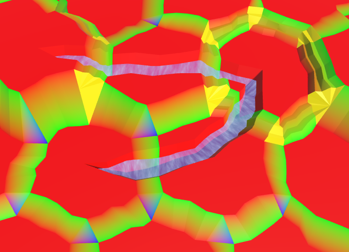
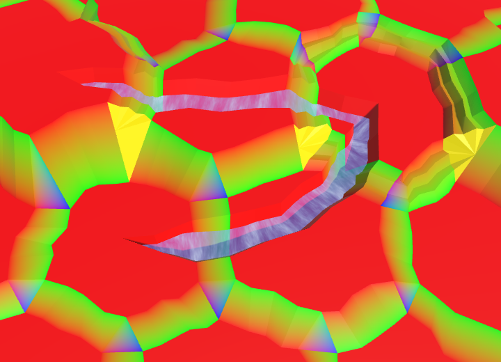
Corners
Cell corners are the most complex, because they have to blend three different textures. We'll use red for the bottom vertex, green for the left vertex, and blue for the right vertex. We start with the single-triangle corners.
	void TriangulateCorner (
		Vector3 bottom, HexCell bottomCell,
		Vector3 left, HexCell leftCell,
		Vector3 right, HexCell rightCell
	) {
		…
		else {
			terrain.AddTriangle(bottom, left, right);
			terrain.AddTriangleColor(color1, color2, color3);
		}

		features.AddWall(bottom, bottomCell, left, leftCell, right, rightCell);
	}
Again, we can use the existing color interpolation code for corners with terraces. It's just between three colors, instead of two. First, terraces that aren't next to cliffs.
	void TriangulateCornerTerraces (
		Vector3 begin, HexCell beginCell,
		Vector3 left, HexCell leftCell,
		Vector3 right, HexCell rightCell
	) {
		Vector3 v3 = HexMetrics.TerraceLerp(begin, left, 1);
		Vector3 v4 = HexMetrics.TerraceLerp(begin, right, 1);
		Color c3 = HexMetrics.TerraceLerp(color1, color2, 1);
		Color c4 = HexMetrics.TerraceLerp(color1, color3, 1);

		terrain.AddTriangle(begin, v3, v4);
		terrain.AddTriangleColor(color1, c3, c4);

		for (int i = 2; i < HexMetrics.terraceSteps; i++) {
			Vector3 v1 = v3;
			Vector3 v2 = v4;
			Color c1 = c3;
			Color c2 = c4;
			v3 = HexMetrics.TerraceLerp(begin, left, i);
			v4 = HexMetrics.TerraceLerp(begin, right, i);
			c3 = HexMetrics.TerraceLerp(color1, color2, i);
			c4 = HexMetrics.TerraceLerp(color1, color3, i);
			terrain.AddQuad(v1, v2, v3, v4);
			terrain.AddQuadColor(c1, c2, c3, c4);
		}

		terrain.AddQuad(v3, v4, left, right);
		terrain.AddQuadColor(c3, c4, color2, color3);
	}
When cliffs are involved, we have to use the TriangulateBoundaryTriangle method. This method used to have the begin and left cell as parameters. However, we now need the relevant splat colors instead, which can vary based on the topology. So change those parameters into colors.
	void TriangulateBoundaryTriangle (
		Vector3 begin, Color beginColor,
		Vector3 left, Color leftColor,
		Vector3 boundary, Color boundaryColor
	) {
		Vector3 v2 = HexMetrics.Perturb(HexMetrics.TerraceLerp(begin, left, 1));
		Color c2 = HexMetrics.TerraceLerp(beginColor, leftColor, 1);

		terrain.AddTriangleUnperturbed(HexMetrics.Perturb(begin), v2, boundary);
		terrain.AddTriangleColor(beginColor, c2, boundaryColor);

		for (int i = 2; i < HexMetrics.terraceSteps; i++) {
			Vector3 v1 = v2;
			Color c1 = c2;
			v2 = HexMetrics.Perturb(HexMetrics.TerraceLerp(begin, left, i));
			c2 = HexMetrics.TerraceLerp(beginColor, leftColor, i);
			terrain.AddTriangleUnperturbed(v1, v2, boundary);
			terrain.AddTriangleColor(c1, c2, boundaryColor);
		}

		terrain.AddTriangleUnperturbed(v2, HexMetrics.Perturb(left), boundary);
		terrain.AddTriangleColor(c2, leftColor, boundaryColor);
	}
Adjust TriangulateCornerTerracesCliff so it uses the correct colors.
	void TriangulateCornerTerracesCliff (
		Vector3 begin, HexCell beginCell,
		Vector3 left, HexCell leftCell,
		Vector3 right, HexCell rightCell
	) {
		…
		Color boundaryColor = Color.Lerp(color1, color3, b);

		TriangulateBoundaryTriangle(
			begin, color1, left, color2, boundary, boundaryColor
		);

		if (leftCell.GetEdgeType(rightCell) == HexEdgeType.Slope) {
			TriangulateBoundaryTriangle(
				left, color2, right, color3, boundary, boundaryColor
			);
		}
		else {
			terrain.AddTriangleUnperturbed(
				HexMetrics.Perturb(left), HexMetrics.Perturb(right), boundary
			);
			terrain.AddTriangleColor(color2, color3, boundaryColor);
		}
	}
And do the same for TriangulateCornerCliffTerraces.
	void TriangulateCornerCliffTerraces (
		Vector3 begin, HexCell beginCell,
		Vector3 left, HexCell leftCell,
		Vector3 right, HexCell rightCell
	) {
		…
		Color boundaryColor = Color.Lerp(color1, color2, b);

		TriangulateBoundaryTriangle(
			right, color3, begin, color1, boundary, boundaryColor
		);

		if (leftCell.GetEdgeType(rightCell) == HexEdgeType.Slope) {
			TriangulateBoundaryTriangle(
				left, color2, right, color3, boundary, boundaryColor
			);
		}
		else {
			terrain.AddTriangleUnperturbed(
				HexMetrics.Perturb(left), HexMetrics.Perturb(right), boundary
			);
			terrain.AddTriangleColor(color2, color3, boundaryColor);
		}
	}
Texture Arrays
Now that our terrain has a splat map, we have to supply our shader with a collection of textures. We can't just assign a C# array of textures to a shader, because the array has to exist as a single entity in GPU memory. We have to use a special Texture2DArray object, which has been supported by Unity since version 5.4.
Wizard
Unfortunately, Unity's editor support for texture arrays is minimal in version 5.5. We cannot simply create a texture array asset and assign textures to it. We have to do it manually. We could either create a texture array in play mode, or create an asset in the editor. Let's go for the asset.
To create our texture array, we'll build a custom wizard. Create a TextureArrayWizard script and place it inside an Editor folder. Instead of MonoBehaviour, it should extend the ScriptableWizard type from the UnityEditor namespace.
using UnityEditor;
using UnityEngine;

public class TextureArrayWizard : ScriptableWizard {
}
We can open our wizard via the generic static ScriptableWizard.DisplayWizard method. Its parameters are the names of the wizard's window and its create button. Invoke this method in a static CreateWizard method.
	static void CreateWizard () {
		ScriptableWizard.DisplayWizard<TextureArrayWizard>(
			"Create Texture Array", "Create"
		);
	}
To access the wizard via the editor, we have to add this method to Unity's menu. This is done by adding the MenuItem attribute to the method. Let's add it to the Assets menu, specifically Assets / Create / Texture Array.
	[MenuItem("Assets/Create/Texture Array")]
	static void CreateWizard () {
		…
	}
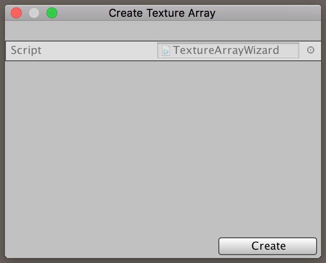
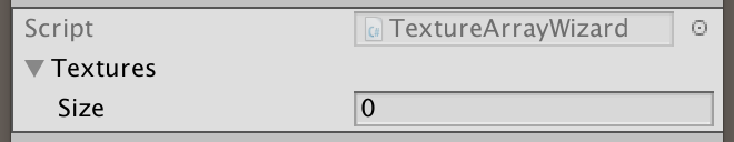
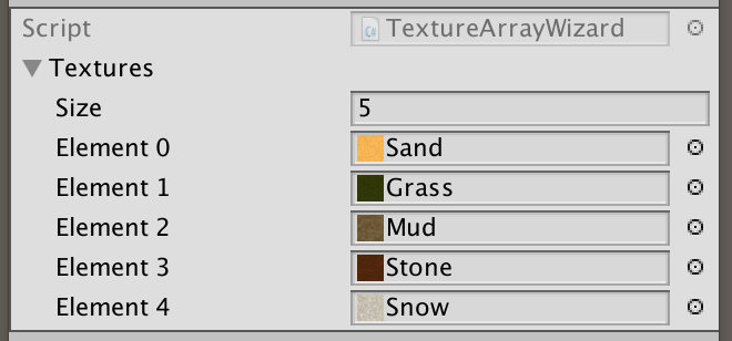
Using the new menu item, we get a popup window for our custom wizard. It's not pretty, but it will get the job done. However, it is still empty. To create the texture array, we need an array of textures. Add a public field for this to our wizard. The default wizard GUI will display it, just like a default inspector does.
public Texture2D[] textures;
Creating Something
When you press the wizard's Create button, it will disappear. Also, Unity will complain that there's no OnWizardCreate method. This is the method that gets invoked when the create button is pressed, so we should add it to our wizard.
	void OnWizardCreate () {
	}
Here is where we create our texture array. At least, if the user has added any textures to the wizard. If not, then there's nothing to create, so we should abort.
	void OnWizardCreate () {
		if (textures.Length == 0) {
			return;
		}
	}
The next step is to ask the user where to save the texture array asset. We can open a save file panel via the EditorUtility.SaveFilePanelInProject method. Its parameters determine the panel name, default file name, the file extension, and description. Texture arrays use the generic asset file extension.
		if (textures.Length == 0) {
			return;
		}
		EditorUtility.SaveFilePanelInProject(
			"Save Texture Array", "Texture Array", "asset", "Save Texture Array"
		);
SaveFilePanelInProject returns the file path that the user selected. If the user canceled the panel, then the path will be the empty string. So we should abort in that case.
		string path = EditorUtility.SaveFilePanelInProject(
			"Save Texture Array", "Texture Array", "asset", "Save Texture Array"
		);
		if (path.Length == 0) {
			return;
		}
Creating a Texture Array
If we got a valid path, we can go on and create a new Texture2DArray object. Its constructor method requires the texture width and height, the array length, the texture format, and whether there are mipmaps. These settings have to be the same for all textures in the array. We'll use the first texture to configure the object. It's up to the user to make sure that all textures have the same format.
		if (path.Length == 0) {
			return;
		}

		Texture2D t = textures[0];
		Texture2DArray textureArray = new Texture2DArray(
			t.width, t.height, textures.Length, t.format, t.mipmapCount > 1
		);
As the texture array is a single GPU resource, it uses the same filter and wrap modes for all textures. Once again, we'll use the first texture to configure this.
		Texture2DArray textureArray = new Texture2DArray(
			t.width, t.height, textures.Length, t.format, t.mipmapCount > 1
		);
		textureArray.anisoLevel = t.anisoLevel;
		textureArray.filterMode = t.filterMode;
		textureArray.wrapMode = t.wrapMode;
Now we can copy the textures to the array, using the Graphics.CopyTexture method. This method copies the raw texture data, one mip level at a time. So we have to loop through all textures and their mip levels. The parameters of the method are two sets consisting of a texture resource, index, and mip level. As the source textures aren't arrays, their index is always zero.
		textureArray.wrapMode = t.wrapMode;

		for (int i = 0; i < textures.Length; i++) {
			for (int m = 0; m < t.mipmapCount; m++) {
				Graphics.CopyTexture(textures[i], 0, m, textureArray, i, m);
			}
		}
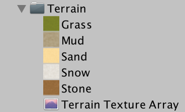
At this point we have a valid texture array in memory, but it is not yet an asset. The final step is to invoke AssetDatabase.CreateAsset with the array and its path. That will write the data to a file in our project, and it will appear in the project window.
		for (int i = 0; i < textures.Length; i++) {
			…
		}

		AssetDatabase.CreateAsset(textureArray, path);
Textures
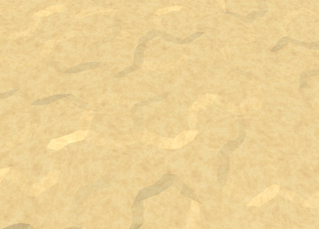
To actually create a texture array, we need source textures. Here are five textures which correspond to the colors that we have been using up to this point. Yellow becomes sand, green becomes grass, blue becomes mud, orange becomes stone, and white becomes snow.


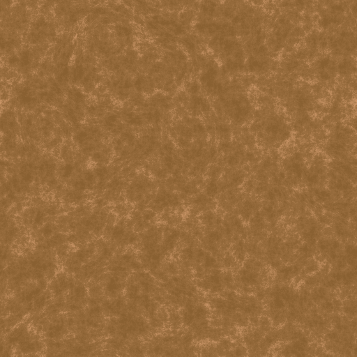
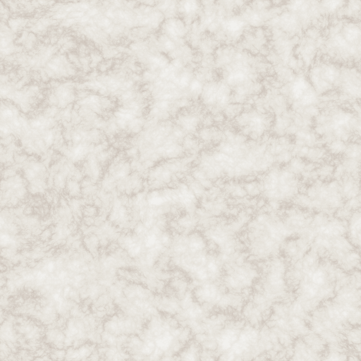
Note that these textures aren't photos of actual terrain, they're subtle pseudorandom patterns. My goal was to suggest recognizable terrain types and details, without clashing with the abstract polygonal terrain. Photorealism would feel out of place. Also, while these patterns add variety, they lack distinct features which would make their tiling immediately obvious.
Add these textures to the wizard's array, making sure that their order matches our colors. So sand first, followed by grass, mud, stone, and finally snow.
After creating the texture array asset, select it and give it a look in the inspector.
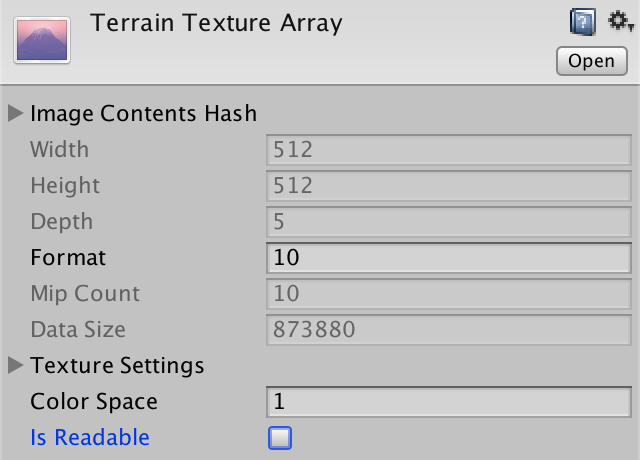
It's a bare-bones display of some of the data of the texture array. Note that there is an Is Readable toggle, which is initially enabled. As we don't need to read pixel data from the array, disable it. We couldn't do this via our wizard, because Texture2DArray has no method or property to access this setting.
(There is a bug in Unity 5.6 that breaks texture arrays in builds on multiple platforms. The workaround is to keep Is Readable enabled. Also, in later versions of Unity you need to set the inspector to debug mode to see most of the data.)
Also note that there is a Color Space field, which is set to 1. This means that the textures are assumed to be in gamma space, which is correct. If they had to be in linear space, we would have to set this field to 0. The constructor of Texture2DArray actually has an extra parameter to set the color space, however Texture2D doesn't expose whether it's in linear space or not, so you'd have to set it manually anyway.
Shader
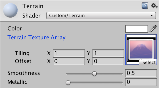
Now that we have our texture array, it's time to make our shader work with it. We're currently using the VertexColors shader to render our terrain. As we'll switch to textures instead of colors, rename it to Terrain. Then turn its _MainTex parameter into a texture array, and assign our asset to it.
Shader "Custom/Terrain" {
	Properties {
		_Color ("Color", Color) = (1,1,1,1)
		_MainTex ("Terrain Texture Array", 2DArray) = "white" {}
		_Glossiness ("Smoothness", Range(0,1)) = 0.5
		_Metallic ("Metallic", Range(0,1)) = 0.0
	}
	…
}
To enable texture arrays on all platforms that support it, we have to increase our shader target level from 3.0 to 3.5.
#pragma target 3.5
As the _MainTex variable now references a texture array, we have to change its type. The exact type depends on the target platform, which is taken care of by the UNITY_DECLARE_TEX2DARRAY macro.
// sampler2D _MainTex;UNITY_DECLARE_TEX2DARRAY(_MainTex);
Like the other shaders, we'll need the XZ world coordinates to sample our terrain textures. So add the world position to the surface shader input structure. Also remove the default UV coordinates, as we don't need them.
		struct Input {
//			float2 uv_MainTex;
			float4 color : COLOR;
			float3 worldPos;
		};
To sample the texture array, we have to use the UNITY_SAMPLE_TEX2DARRAY macro. It requires three coordinates to sample the array. The first two are regular UV coordinates. We'll use the world XZ coordinates, scaled by 0.02. That produces a good texture resolution when fully zoomed in, with textures tiling roughly every four cells.
The third coordinate is used to index the texture array, just like a regular array. As the coordinates are floats, the GPU rounds them before indexing the array. As we don't yet know which texture is needed, let's always use the first one. Also, no longer factor the vertex color into the final result, as that's the splat map.
		void surf (Input IN, inout SurfaceOutputStandard o) {
			float2 uv = IN.worldPos.xz * 0.02;
			fixed4 c = UNITY_SAMPLE_TEX2DARRAY(_MainTex, float3(uv, 0));
			o.Albedo = c.rgb * _Color;
			o.Metallic = _Metallic;
			o.Smoothness = _Glossiness;
			o.Alpha = c.a;
		}
Selecting Textures
We have a terrain splat map which blends between three types per triangle. We have a texture array with a texture for each terrain type. We have a shader that can sample the texture array. But we do not yet have a means to tell the shader which textures to select, per triangle.
As each triangle blends between up to three types, we need to associate three indices with every triangle. As we cannot store information per triangle, we'll have to store the indices per vertex instead. All three vertices of a triangle will simply store the same indices, just like a solid color.
Mesh Data
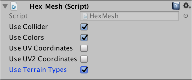
We can use one of the mesh's UV sets to store the indices. Because there are three indices per vertex, the existing 2D UV sets aren't sufficient. Fortunately, UV sets can contain up to four coordinates. So let's add a second Vector3 list to HexMesh, which we'll refer to as the terrain types.
	public bool useCollider, useColors, useUVCoordinates, useUV2Coordinates;
	public bool useTerrainTypes;

	[NonSerialized] List<Vector3> vertices, terrainTypes;
Enable the terrain types for the Terrain child object of the Hex Grid Chunk prefab.
Grab another Vector3 list for the terrain types when clearing the mesh, if needed.
	public void Clear () {
		…
		if (useTerrainTypes) {
			terrainTypes = ListPool<Vector3>.Get();
		}
		triangles = ListPool<int>.Get();
	}
When applying the mesh data, store the terrain types in the third UV set. That way, it won't clash with the other two sets, if we were to ever use them together.
	public void Apply () {
		…
		if (useTerrainTypes) {
			hexMesh.SetUVs(2, terrainTypes);
			ListPool<Vector3>.Add(terrainTypes);
		}
		hexMesh.SetTriangles(triangles, 0);
		…
	}
We'll use a Vector3 to set the terrain types of a triangle. As they're uniform across a triangle, simply add the same data three times.
	public void AddTriangleTerrainTypes (Vector3 types) {
		terrainTypes.Add(types);
		terrainTypes.Add(types);
		terrainTypes.Add(types);
	}
Blending across a quad works the same way. All four vertices have the same types.
	public void AddQuadTerrainTypes (Vector3 types) {
		terrainTypes.Add(types);
		terrainTypes.Add(types);
		terrainTypes.Add(types);
		terrainTypes.Add(types);
	}
Edge Fans
Now we have to add the types to the mesh data in HexGridChunk. Let's start with TriangulateEdgeFan. First, let's separate the vertex and color method invocations, for readability. Also recall that everywhere we invoke this method, we supply it with color1. So we can use that color directly, instead of relying on the parameter.
	void TriangulateEdgeFan (Vector3 center, EdgeVertices edge, Color color) {
		terrain.AddTriangle(center, edge.v1, edge.v2);
//		terrain.AddTriangleColor(color);
		terrain.AddTriangle(center, edge.v2, edge.v3);
//		terrain.AddTriangleColor(color);
		terrain.AddTriangle(center, edge.v3, edge.v4);
//		terrain.AddTriangleColor(color);
		terrain.AddTriangle(center, edge.v4, edge.v5);
//		terrain.AddTriangleColor(color);

		terrain.AddTriangleColor(color1);
		terrain.AddTriangleColor(color1);
		terrain.AddTriangleColor(color1);
		terrain.AddTriangleColor(color1);
	}
After the colors, we add the terrain types. As the type varies per triangle, it has to be a parameter, replacing the color. Use this single type to construct a Vector3. Only the first channel matters, because the splat map is always red in this case. As all three vector components need to be set to something, let's set them all to the same type.
	void TriangulateEdgeFan (Vector3 center, EdgeVertices edge, float type) {
		…

		Vector3 types;
		types.x = types.y = types.z = type;
		terrain.AddTriangleTerrainTypes(types);
		terrain.AddTriangleTerrainTypes(types);
		terrain.AddTriangleTerrainTypes(types);
		terrain.AddTriangleTerrainTypes(types);
	}
Now we have to adjust all invocations of this method, replacing the color argument with the cell's terrain type index. Make this adjustment in TriangulateWithoutRiver, TriangulateAdjacentToRiver, and TriangulateWithRiverBeginOrEnd.
// TriangulateEdgeFan(center, e, color1);TriangulateEdgeFan(center, e, cell.TerrainTypeIndex);
At this point, entering play mode will produce errors which say that the third UV sets of the meshes are out of bounds. That's because we're not yet adding the terrain types to every triangle and quad. So let's continue updating HexGridChunk.
Edge Strips
When creating an edge strip, we now have to know what the terrain types on both side are. So add them as parameters. Then construct a types vector with the first two channels set to these types. The third channel doesn't matter, just make it equal to the first. Add the types to the quads after adding the colors.
	void TriangulateEdgeStrip (
		EdgeVertices e1, Color c1, float type1,
		EdgeVertices e2, Color c2, float type2,
		bool hasRoad = false
	) {
		terrain.AddQuad(e1.v1, e1.v2, e2.v1, e2.v2);
		terrain.AddQuad(e1.v2, e1.v3, e2.v2, e2.v3);
		terrain.AddQuad(e1.v3, e1.v4, e2.v3, e2.v4);
		terrain.AddQuad(e1.v4, e1.v5, e2.v4, e2.v5);

		terrain.AddQuadColor(c1, c2);
		terrain.AddQuadColor(c1, c2);
		terrain.AddQuadColor(c1, c2);
		terrain.AddQuadColor(c1, c2);

		Vector3 types;
		types.x = types.z = type1;
		types.y = type2;
		terrain.AddQuadTerrainTypes(types);
		terrain.AddQuadTerrainTypes(types);
		terrain.AddQuadTerrainTypes(types);
		terrain.AddQuadTerrainTypes(types);

		if (hasRoad) {
			TriangulateRoadSegment(e1.v2, e1.v3, e1.v4, e2.v2, e2.v3, e2.v4);
		}
	}
Now we have to update the invocations of TriangulateEdgeStrip. First, TriangulateAdjacentToRiver, TriangulateWithRiverBeginOrEnd, and TriangulateWithRiver have to use the cell's type for both sides of the edge strip.
// TriangulateEdgeStrip(m, color1, e, color1);TriangulateEdgeStrip( m, color1, cell.TerrainTypeIndex, e, color1, cell.TerrainTypeIndex );
Next, the simplest edge case of TriangulateConnection has to use the cell's type for the near edge, and the neighbor's type for the far edge. They might be the same, but could also be different.
	void TriangulateConnection (
		HexDirection direction, HexCell cell, EdgeVertices e1
	) {
		…
		if (cell.GetEdgeType(direction) == HexEdgeType.Slope) {
			TriangulateEdgeTerraces(e1, cell, e2, neighbor, hasRoad);
		}
		else {
//			TriangulateEdgeStrip(e1, color1, e2, color2, hasRoad);
			TriangulateEdgeStrip(
				e1, color1, cell.TerrainTypeIndex,
				e2, color2, neighbor.TerrainTypeIndex, hasRoad
			);
		}
		…
	}
The same is true in TriangulateEdgeTerraces, which invokes TriangulateEdgeStrip three times. The types are uniform across the terraces.
	void TriangulateEdgeTerraces (
		EdgeVertices begin, HexCell beginCell,
		EdgeVertices end, HexCell endCell,
		bool hasRoad
	) {
		EdgeVertices e2 = EdgeVertices.TerraceLerp(begin, end, 1);
		Color c2 = HexMetrics.TerraceLerp(color1, color2, 1);
		float t1 = beginCell.TerrainTypeIndex;
		float t2 = endCell.TerrainTypeIndex;

		TriangulateEdgeStrip(begin, color1, t1, e2, c2, t2, hasRoad);

		for (int i = 2; i < HexMetrics.terraceSteps; i++) {
			EdgeVertices e1 = e2;
			Color c1 = c2;
			e2 = EdgeVertices.TerraceLerp(begin, end, i);
			c2 = HexMetrics.TerraceLerp(color1, color2, i);
			TriangulateEdgeStrip(e1, c1, t1, e2, c2, t2, hasRoad);
		}

		TriangulateEdgeStrip(e2, c2, t1, end, color2, t2, hasRoad);
	}
Corners
The simplest corner case is a single triangle. The bottom cell provides the first type, the left cell the second, and the right cell the third. Construct a types vector with them and add it to the triangle.
	void TriangulateCorner (
		Vector3 bottom, HexCell bottomCell,
		Vector3 left, HexCell leftCell,
		Vector3 right, HexCell rightCell
	) {
		…
		else {
			terrain.AddTriangle(bottom, left, right);
			terrain.AddTriangleColor(color1, color2, color3);
			Vector3 types;
			types.x = bottomCell.TerrainTypeIndex;
			types.y = leftCell.TerrainTypeIndex;
			types.z = rightCell.TerrainTypeIndex;
			terrain.AddTriangleTerrainTypes(types);
		}

		features.AddWall(bottom, bottomCell, left, leftCell, right, rightCell);
	}
We use the same approach in TriangulateCornerTerraces, except that we're creating a bunch of quads as well.
	void TriangulateCornerTerraces (
		Vector3 begin, HexCell beginCell,
		Vector3 left, HexCell leftCell,
		Vector3 right, HexCell rightCell
	) {
		Vector3 v3 = HexMetrics.TerraceLerp(begin, left, 1);
		Vector3 v4 = HexMetrics.TerraceLerp(begin, right, 1);
		Color c3 = HexMetrics.TerraceLerp(color1, color2, 1);
		Color c4 = HexMetrics.TerraceLerp(color1, color3, 1);
		Vector3 types;
		types.x = beginCell.TerrainTypeIndex;
		types.y = leftCell.TerrainTypeIndex;
		types.z = rightCell.TerrainTypeIndex;

		terrain.AddTriangle(begin, v3, v4);
		terrain.AddTriangleColor(color1, c3, c4);
		terrain.AddTriangleTerrainTypes(types);

		for (int i = 2; i < HexMetrics.terraceSteps; i++) {
			Vector3 v1 = v3;
			Vector3 v2 = v4;
			Color c1 = c3;
			Color c2 = c4;
			v3 = HexMetrics.TerraceLerp(begin, left, i);
			v4 = HexMetrics.TerraceLerp(begin, right, i);
			c3 = HexMetrics.TerraceLerp(color1, color2, i);
			c4 = HexMetrics.TerraceLerp(color1, color3, i);
			terrain.AddQuad(v1, v2, v3, v4);
			terrain.AddQuadColor(c1, c2, c3, c4);
			terrain.AddQuadTerrainTypes(types);
		}

		terrain.AddQuad(v3, v4, left, right);
		terrain.AddQuadColor(c3, c4, color2, color3);
		terrain.AddQuadTerrainTypes(types);
	}
When terraces and cliffs mix, we need to use TriangulateBoundaryTriangle. Simply give it a types vector parameter, and add it to all its triangles.
	void TriangulateBoundaryTriangle (
		Vector3 begin, Color beginColor,
		Vector3 left, Color leftColor,
		Vector3 boundary, Color boundaryColor, Vector3 types
	) {
		Vector3 v2 = HexMetrics.Perturb(HexMetrics.TerraceLerp(begin, left, 1));
		Color c2 = HexMetrics.TerraceLerp(beginColor, leftColor, 1);

		terrain.AddTriangleUnperturbed(HexMetrics.Perturb(begin), v2, boundary);
		terrain.AddTriangleColor(beginColor, c2, boundaryColor);
		terrain.AddTriangleTerrainTypes(types);

		for (int i = 2; i < HexMetrics.terraceSteps; i++) {
			Vector3 v1 = v2;
			Color c1 = c2;
			v2 = HexMetrics.Perturb(HexMetrics.TerraceLerp(begin, left, i));
			c2 = HexMetrics.TerraceLerp(beginColor, leftColor, i);
			terrain.AddTriangleUnperturbed(v1, v2, boundary);
			terrain.AddTriangleColor(c1, c2, boundaryColor);
			terrain.AddTriangleTerrainTypes(types);
		}

		terrain.AddTriangleUnperturbed(v2, HexMetrics.Perturb(left), boundary);
		terrain.AddTriangleColor(c2, leftColor, boundaryColor);
		terrain.AddTriangleTerrainTypes(types);
	}
In TriangulateCornerTerracesCliff, create a types vector using the provided cells. Then add it to the single triangle and pass it to TriangulateBoundaryTriangle.
	void TriangulateCornerTerracesCliff (
		Vector3 begin, HexCell beginCell,
		Vector3 left, HexCell leftCell,
		Vector3 right, HexCell rightCell
	) {
		float b = 1f / (rightCell.Elevation - beginCell.Elevation);
		if (b < 0) {
			b = -b;
		}
		Vector3 boundary = Vector3.Lerp(
			HexMetrics.Perturb(begin), HexMetrics.Perturb(right), b
		);
		Color boundaryColor = Color.Lerp(color1, color3, b);
		Vector3 types;
		types.x = beginCell.TerrainTypeIndex;
		types.y = leftCell.TerrainTypeIndex;
		types.z = rightCell.TerrainTypeIndex;

		TriangulateBoundaryTriangle(
			begin, color1, left, color2, boundary, boundaryColor, types
		);

		if (leftCell.GetEdgeType(rightCell) == HexEdgeType.Slope) {
			TriangulateBoundaryTriangle(
				left, color2, right, color3, boundary, boundaryColor, types
			);
		}
		else {
			terrain.AddTriangleUnperturbed(
				HexMetrics.Perturb(left), HexMetrics.Perturb(right), boundary
			);
			terrain.AddTriangleColor(color2, color3, boundaryColor);
			terrain.AddTriangleTerrainTypes(types);
		}
	}
The same goes for TriangulateCornerCliffTerraces.
	void TriangulateCornerCliffTerraces (
		Vector3 begin, HexCell beginCell,
		Vector3 left, HexCell leftCell,
		Vector3 right, HexCell rightCell
	) {
		float b = 1f / (leftCell.Elevation - beginCell.Elevation);
		if (b < 0) {
			b = -b;
		}
		Vector3 boundary = Vector3.Lerp(
			HexMetrics.Perturb(begin), HexMetrics.Perturb(left), b
		);
		Color boundaryColor = Color.Lerp(color1, color2, b);
		Vector3 types;
		types.x = beginCell.TerrainTypeIndex;
		types.y = leftCell.TerrainTypeIndex;
		types.z = rightCell.TerrainTypeIndex;

		TriangulateBoundaryTriangle(
			right, color3, begin, color1, boundary, boundaryColor, types
		);

		if (leftCell.GetEdgeType(rightCell) == HexEdgeType.Slope) {
			TriangulateBoundaryTriangle(
				left, color2, right, color3, boundary, boundaryColor, types
			);
		}
		else {
			terrain.AddTriangleUnperturbed(
				HexMetrics.Perturb(left), HexMetrics.Perturb(right), boundary
			);
			terrain.AddTriangleColor(color2, color3, boundaryColor);
			terrain.AddTriangleTerrainTypes(types);
		}
	}
Rivers
The last method that requires an update is TriangulateWithRiver. As we're inside a cell center here, we're dealing with the current cell's type only. So create a vector for it and add it to the triangles and quads.
	void TriangulateWithRiver (
		HexDirection direction, HexCell cell, Vector3 center, EdgeVertices e
	) {
		…

		terrain.AddTriangleColor(color1);
		terrain.AddQuadColor(color1);
		terrain.AddQuadColor(color1);
		terrain.AddTriangleColor(color1);

		Vector3 types;
		types.x = types.y = types.z = cell.TerrainTypeIndex;
		terrain.AddTriangleTerrainTypes(types);
		terrain.AddQuadTerrainTypes(types);
		terrain.AddQuadTerrainTypes(types);
		terrain.AddTriangleTerrainTypes(types);

		…
	}
Blending the Types
By now the meshes contain the required terrain indices. All that's left is for the Terrain shader to actually use them. To get the indices to the fragment shader, we have to pass them through the vertex shader first. We can do so with a custom vertex function, just like we did in the Estuary shader. In this case, we add a float3 terrain field to the input structure and copy v.texcoord2.xyz to it.
		#pragma surface surf Standard fullforwardshadows vertex:vert
		#pragma target 3.5

		…

		struct Input {
			float4 color : COLOR;
			float3 worldPos;
			float3 terrain;
		};

		void vert (inout appdata_full v, out Input data) {
			UNITY_INITIALIZE_OUTPUT(Input, data);
			data.terrain = v.texcoord2.xyz;
		}
We have to sample the texture array three times per fragment. So let's create a convenient function to construct the texture coordinates, sample the array, and modulate the sample with the splat map for one index.
		float4 GetTerrainColor (Input IN, int index) {
			float3 uvw = float3(IN.worldPos.xz * 0.02, IN.terrain[index]);
			float4 c = UNITY_SAMPLE_TEX2DARRAY(_MainTex, uvw);
			return c * IN.color[index];
		}

		void surf (Input IN, inout SurfaceOutputStandard o) {
			…
		}
Using this function, it's simple to sample the texture array three times and combine the results.
		void surf (Input IN, inout SurfaceOutputStandard o) {
//			float2 uv = IN.worldPos.xz * 0.02;
			fixed4 c =
				GetTerrainColor(IN, 0) +
				GetTerrainColor(IN, 1) +
				GetTerrainColor(IN, 2);
			o.Albedo = c.rgb * _Color;
			o.Metallic = _Metallic;
			o.Smoothness = _Glossiness;
			o.Alpha = c.a;
		}
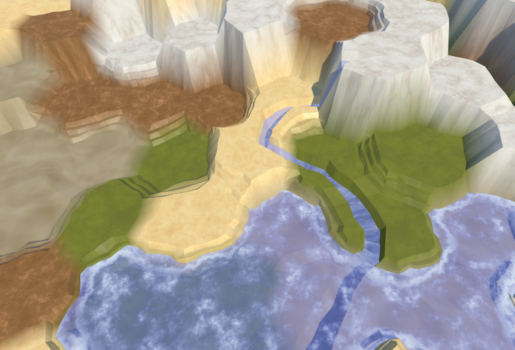
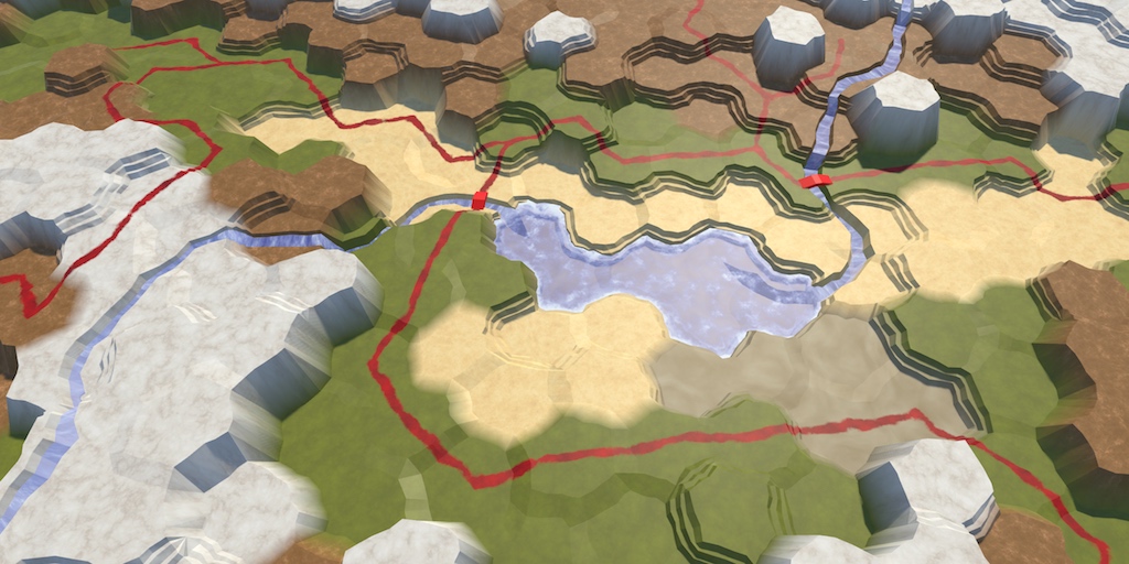
We can now paint our terrain with textures. They blend just like the solid colors did. Because we're using the world position as UV coordinates, they don't change with altitude. As a result, the textures are stretched along steep cliffs. If the textures are neutral enough and have plenty of variety, the results can be acceptable. Otherwise, you'll get big ugly streaks. You could try to hide that with additional geometry or cliff textures, but that's not part of this tutorial.
Cleaning Up
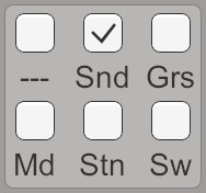
Now that we're using textures instead of colors, it makes sense to adjust our editor panel. You could make a neat interface which even shows the terrain textures, but I'll settle for abbreviations that fit the existing layout.
Also, HexCell no longer needs a color property, so delete it.
// public Color Color {// get {// return HexMetrics.colors[terrainTypeIndex];// }// }
The color array and associated code can also be removed from HexGrid.
// public Color[] colors;… void Awake () { HexMetrics.noiseSource = noiseSource; HexMetrics.InitializeHashGrid(seed);// HexMetrics.colors = colors;CreateMap(cellCountX, cellCountZ); } … … void OnEnable () { if (!HexMetrics.noiseSource) { HexMetrics.noiseSource = noiseSource; HexMetrics.InitializeHashGrid(seed);// HexMetrics.colors = colors;} }
And finally, HexMetrics no longer needs the color array either.
// public static Color[] colors;
The next tutorial is Distances.