Rendering 10
More Complexity
- Bake self-shadowing into a material.
- Add details to part of a surface.
- Support more efficient shader variants.
- Edit multiple materials at once.
This is the tenth part of a tutorial series about rendering. Last time, we used multiple textures to create complex materials. We'll add some more complexity this time, and also support multi-material editing.
This tutorial was made with Unity 5.4.3f1.
Occluded Areas
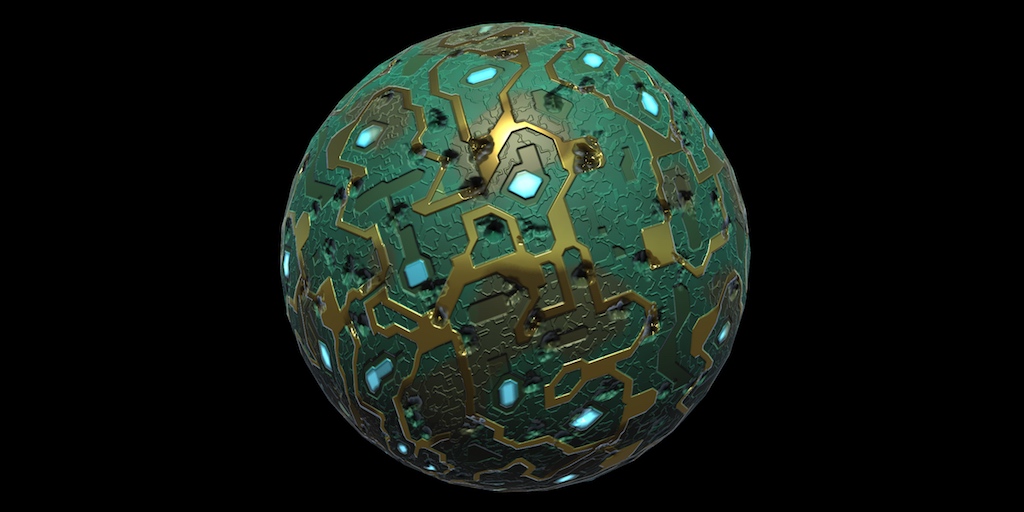
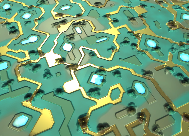
Even through we can create materials that appear complex, it is just an illusion. The triangles are still flat. Normal maps can give the impression of depth, but that only works for direct light. There is no self-shadowing. Parts that are supposedly higher, should casts shadows on areas that are lower. But this doesn't happen. This is most obvious when the normal map would suggest that there are small holes, dents, or cracks.
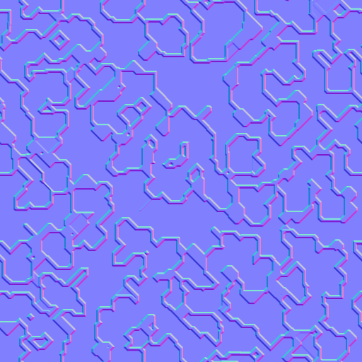
For example, let's say that someone has been shooting at our circuit board. The shots didn't go through the board, but left significant dents. Here's an adjusted normal map for that.
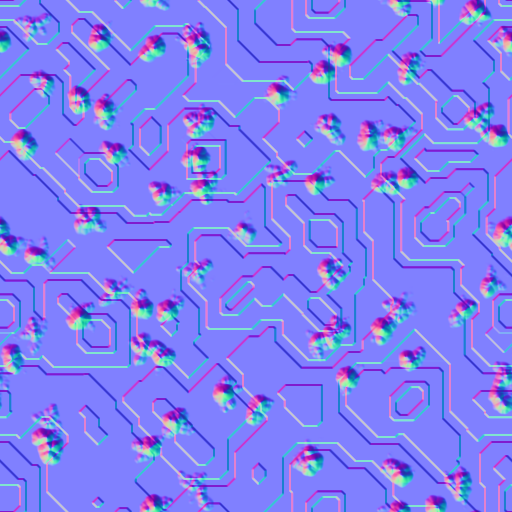
When using this normal map, the circuitry material indeed appears dented. But the deepest parts of the dents are lit just as well as the undented surface. There isn't any self-shadowing going on in the dents. As as result, they do not appear to be very deep.
Occlusion Map
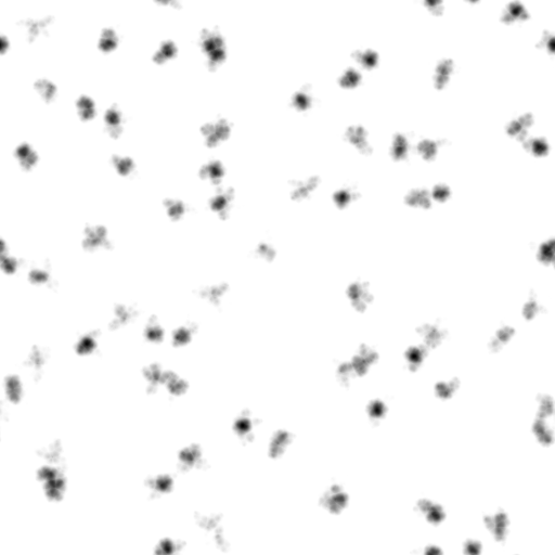
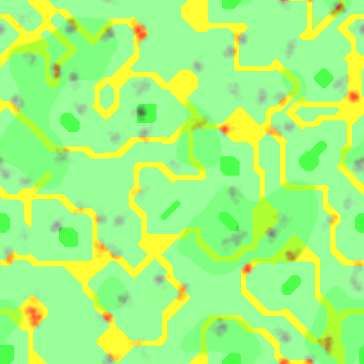
To add self-shadowing, we can use what's known as an occlusion map. You can think of this as a fixed shadow map that's part of the material. Here is such a map for the dented circuitry, as a grayscale image.
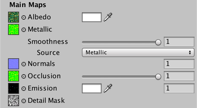
To use this map, add a texture property for this map to our shader. Also add an occlusion strength slider property, so we can fine-tune it.
		[NoScaleOffset] _OcclusionMap ("Occlusion", 2D) = "white" {}
		_OcclusionStrength("Occlusion Strength", Range(0, 1)) = 1
Just like with the metallic map, let's use a shader feature to only sample the occlusion map when it is set. Add the feature to the base pass only, don't worry about additional lights now.
			#pragma shader_feature _ _SMOOTHNESS_ALBEDO _SMOOTHNESS_METALLIC
			#pragma shader_feature _OCCLUSION_MAP
			#pragma shader_feature _EMISSION_MAP
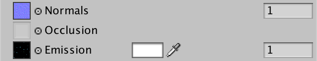
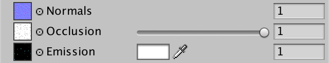
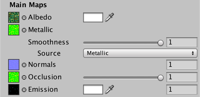
Occlusion UI
Because we have a custom shader GUI, we have to manually add the new properties to our shader's UI. So add a DoOcclusion step to MyLightingShaderGUI.DoMain.
	void DoMain () {
		…
		DoNormals();
		DoOcclusion();
		DoEmission();
		editor.TextureScaleOffsetProperty(mainTex);
	}
This new method is nearly identical do DoMetallic, which is also about a map, a slider, and a keyword. So duplicate that method and make the required changes. While DoMetallic shows the slider when there is no map, we have to do the opposite here. Also, Unity's standard shader uses the G color channel of the occlusion map, so we'll do this as well. Indicate this in the tooltip.
	void DoOcclusion () {
		MaterialProperty map = FindProperty("_OcclusionMap");
		EditorGUI.BeginChangeCheck();
		editor.TexturePropertySingleLine(
			MakeLabel(map, "Occlusion (G)"), map,
			map.textureValue ? FindProperty("_OcclusionStrength") : null
		);
		if (EditorGUI.EndChangeCheck()) {
			SetKeyword("_OCCLUSION_MAP", map.textureValue);
		}
	}
Adding Shadows
To access the map in our include file, add a sampler and float variable.
sampler2D _OcclusionMap;
float _OcclusionStrength;
Create a function to take care of sampling the map, if it exists. If not, the light should not be modulated, so the result is simply 1.
float GetOcclusion (Interpolators i) {
	#if defined(_OCCLUSION_MAP)
		return tex2D(_OcclusionMap, i.uv.xy).g;
	#else
		return 1;
	#endif
}
When the occlusion strength is zero, the map should't affect the light at all. Thus, the function should return 1. When at full strength, the result is exactly what's in the map. We can do this by interpolating between 1 and the map, based on the slider.
return lerp(1, tex2D(_OcclusionMap, i.uv.xy).g, _OcclusionStrength);
To apply the shadows to the light, we have to factor the occlusion into the light attention inside CreateLight.
UnityLight CreateLight (Interpolators i) {
	…

	UNITY_LIGHT_ATTENUATION(attenuation, i, i.worldPos);
	attenuation *= GetOcclusion(i);
	light.color = _LightColor0.rgb * attenuation;
	light.ndotl = DotClamped(i.normal, light.dir);
	return light;
}
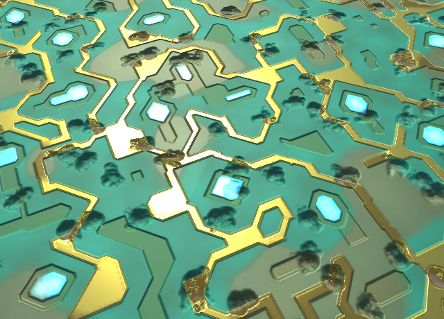
Shadowing Indirect Light
The dents have become darker, but overall not by much. That's because a lot of the light is actually indirect light in this scene. As our occlusion map is not specific to any light, we can apply it to indirect light as well. This is done by modulating both the diffuse and specular indirect light.
UnityIndirect CreateIndirectLight (Interpolators i, float3 viewDir) {
	…

	#if defined(FORWARD_BASE_PASS)
		…

		float occlusion = GetOcclusion(i);
		indirectLight.diffuse *= occlusion;
		indirectLight.specular *= occlusion;
	#endif

	return indirectLight;
}
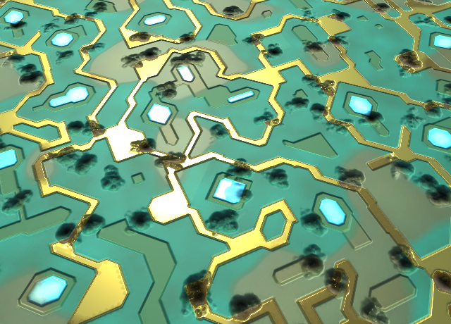
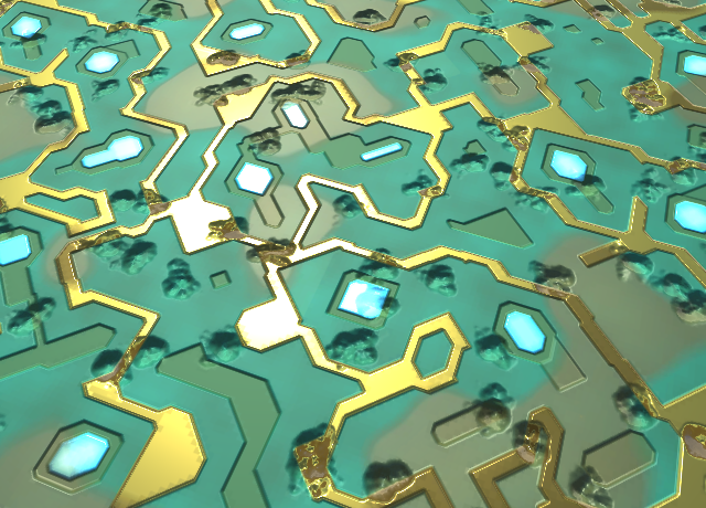
This produces much stronger shadows. In fact, they might be too strong. As the occlusion map is based on the surface shape and not on a specific light, it makes sense that it is only applied to indirect light. Light coming from all directions is reduced the deeper you go into a dent. But when a light shines directly in it, the dent should be fully lit. So let's remove occlusion from direct lights.
UnityLight CreateLight (Interpolators i) {
	…

	UNITY_LIGHT_ATTENUATION(attenuation, i, i.worldPos);
//	attenuation *= GetOcclusion(i);
	light.color = _LightColor0.rgb * attenuation;
	light.ndotl = DotClamped(i.normal, light.dir);
	return light;
}
As far as occlusion maps go, this is as realistic as it can get. Having said that, you'll often find games where occlusion maps are applied to direct lights as well. Unity's older shaders did this too. While that is not realistic, it does give artist more control over lighting.
Merging Maps
We're only using one channel of the occlusion map, the G channel. The metallic map for circuitry is stored in the R channel, and the smoothness is stored in the alpha channel. This means that we could combine all three maps into a single texture. Here is such a map.
The shader doesn't know that we're reusing the texture, so it will still sample it a second time for the occlusion map. But using a single texture does reduce memory and storage requirements. By using DXT5 compression, our three 512×512 maps only require 341KB. This does mean that the metallic and occlusion maps are combined into a single gradient, potentially reducing quality. Fortunately, these maps usually aren't that detailed and don't need to be very accurate. So the results are often acceptable.
Masking Details
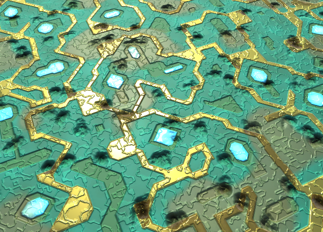
Our circuitry material is lacking details. Let's do something about that. Here is a detail albedo map and normal map.

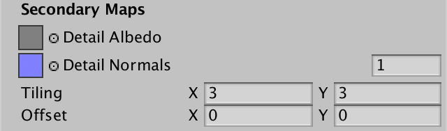
Import then and set the texture to fade out mipmap. Assign the textures and use full-strength normals. These details shouldn't be too small, a 3 by 3 tiling works well.
Detail Mask
The details cover the entire surface, but this doesn't look so good. It's better is the details don't cover the metal parts. We could use a mask texture to control where details show up. This works like a binary splat map, like we used in part 3, Combining Textures. The difference is that a value of 0 means no details, and a value of 1 means full details.
Here is a detail mask that prevents details from showing up on the metal parts. For added variety, it also reduces and even eliminates them from the lower regions of the circuit board. And the details got wiped out wherever dents were punched into the board.
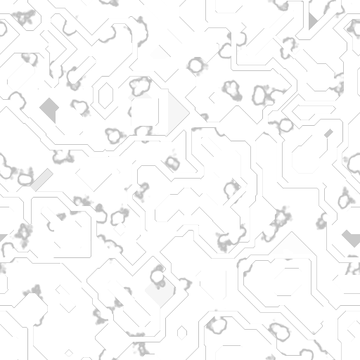
Unity's standard shader uses the alpha channel of the detail mask, so we use that channel as well. The image above has all four color channels set to the same value.
Add a property for this map to our shader.
[NoScaleOffset] _DetailMask ("Detail Mask", 2D) = "white" {}
As many materials won't have a detail mask, give it a shader feature as well. It's needed in both the base and the additive passes.
#pragma shader_feature _DETAIL_MASK
Add the requires variable and a function to get the mask data to our include file.
sampler2D _MainTex, _DetailTex, _DetailMask;

…

float GetDetailMask (Interpolators i) {
	#if defined (_DETAIL_MASK)
		return tex2D(_DetailMask, i.uv.xy).a;
	#else
		return 1;
	#endif
}
Add the map to our UI as well, below the emission map and color. In this case, it's a single texture property combined with a shader keyword.
	void DoMain () {
		…
		DoEmission();
		DoDetailMask();
		editor.TextureScaleOffsetProperty(mainTex);
	}

	…

	void DoDetailMask () {
		MaterialProperty mask = FindProperty("_DetailMask");
		EditorGUI.BeginChangeCheck();
		editor.TexturePropertySingleLine(
			MakeLabel(map, "Detail Mask (A)"), mask
		);
		if (EditorGUI.EndChangeCheck()) {
			SetKeyword("_DETAIL_MASK", mask.textureValue);
		}
	}
Albedo Details
To mask the details, we'll have to adjust our include file again. Instead of always multiplying albedo with the details, we have to interpolate between the unmodified and modified albedo, based on the mask. While we're at it, let's put the retrieval of the albedo into its own function, just like for all the other properties.
float3 GetAlbedo (Interpolators i) {
	float3 albedo = tex2D(_MainTex, i.uv.xy).rgb * _Tint.rgb;
	float3 details = tex2D(_DetailTex, i.uv.zw) * unity_ColorSpaceDouble;
	albedo = lerp(albedo, albedo * details, GetDetailMask(i));
	return albedo;
}

…

float4 MyFragmentProgram (Interpolators i) : SV_TARGET {
	…

//	float3 albedo = tex2D(_MainTex, i.uv.xy).rgb * _Tint.rgb;
//	albedo *= tex2D(_DetailTex, i.uv.zw) * unity_ColorSpaceDouble;

	float3 specularTint;
	float oneMinusReflectivity;
	float3 albedo = DiffuseAndSpecularFromMetallic(
		GetAlbedo(i), GetMetallic(i), specularTint, oneMinusReflectivity
	);

	…
}
Normal Details
We have to make the same adjustment for the normal vector. In this case, no details corresponds with an unmodified upward-facing tangent-space normal vector. So we replace the original detail normal by an interpolation between that vector and its original value, once again based on the detail mask.
void InitializeFragmentNormal(inout Interpolators i) {
	float3 mainNormal =
		UnpackScaleNormal(tex2D(_NormalMap, i.uv.xy), _BumpScale);
	float3 detailNormal =
		UnpackScaleNormal(tex2D(_DetailNormalMap, i.uv.zw), _DetailBumpScale);
	detailNormal = lerp(float3(0, 0, 1), detailNormal, GetDetailMask(i));
	float3 tangentSpaceNormal = BlendNormals(mainNormal, detailNormal);

	…
}

More Keywords
We've been using shader features to enable shader code that samples and includes various maps into our lighting equation. Unity's standard shader does this as well. That's the idea of an uber shader. It can do many things, but has variants for many flavors of use.
The standard shader also has shader features to toggle the use of normal and detail maps. Normal maps are enabled when either a main or detail normal map is assigned. And details are enabled when either a detail albedo or normal is set.
Let's add these features to our shader as well. But let's keep it simple and toggle each map independently. First, let's set a keyword based on the existence of a detail albedo map.
	void DoSecondary () {
		GUILayout.Label("Secondary Maps", EditorStyles.boldLabel);

		MaterialProperty detailTex = FindProperty("_DetailTex");
		EditorGUI.BeginChangeCheck();
		editor.TexturePropertySingleLine(
			MakeLabel(detailTex, "Albedo (RGB) multiplied by 2"), detailTex
		);
		if (EditorGUI.EndChangeCheck()) {
			SetKeyword("_DETAIL_ALBEDO_MAP", detailTex.textureValue);
		}
		DoSecondaryNormals();
		editor.TextureScaleOffsetProperty(detailTex);
	}
Next, a keyword based on the main normal map.
	void DoNormals () {
		MaterialProperty map = FindProperty("_NormalMap");
		EditorGUI.BeginChangeCheck();
		editor.TexturePropertySingleLine(
			MakeLabel(map), map,
			map.textureValue ? FindProperty("_BumpScale") : null
		);
		if (EditorGUI.EndChangeCheck()) {
			SetKeyword("_NORMAL_MAP", map.textureValue);
		}
	}
And similar for the detail normal map.
	void DoSecondaryNormals () {
		MaterialProperty map = FindProperty("_DetailNormalMap");
		EditorGUI.BeginChangeCheck();
		editor.TexturePropertySingleLine(
			MakeLabel(map), map,
			map.textureValue ? FindProperty("_DetailBumpScale") : null
		);
		if (EditorGUI.EndChangeCheck()) {
			SetKeyword("_DETAIL_NORMAL_MAP", map.textureValue);
		}
	}
More Shader Variants
To make this work, add a new shader features for each keyword to our shader passes. First, the base pass.
			#pragma shader_feature _METALLIC_MAP
			#pragma shader_feature _ _SMOOTHNESS_ALBEDO _SMOOTHNESS_METALLIC
			#pragma shader_feature _NORMAL_MAP
			#pragma shader_feature _OCCLUSION_MAP
			#pragma shader_feature _EMISSION_MAP
			#pragma shader_feature _DETAIL_MASK
			#pragma shader_feature _DETAIL_ALBEDO_MAP
			#pragma shader_feature _DETAIL_NORMAL_MAP
Then, the additive pass.
			#pragma shader_feature _METALLIC_MAP
			#pragma shader_feature _ _SMOOTHNESS_ALBEDO _SMOOTHNESS_METALLIC
			#pragma shader_feature _NORMAL_MAP
			#pragma shader_feature _DETAIL_MASK
			#pragma shader_feature _DETAIL_ALBEDO_MAP
			#pragma shader_feature _DETAIL_NORMAL_MAP
The amount of shader variants has now increased a lot. However, to activate the keywords in a material, you'll have to change all the relevant maps via the inspector. Otherwise the shader GUI will not properly set the keywords. This isn't an issue when creating new materials, but existing ones need to be refreshed after this change.
Using the Keywords
Now we have to change the include file to take advantage of the new keywords. First, GetAlbedo might be able to leave out the detail map part.
float3 GetAlbedo (Interpolators i) {
	float3 albedo = tex2D(_MainTex, i.uv.xy).rgb * _Tint.rgb;
	#if defined (_DETAIL_ALBEDO_MAP)
		float3 details = tex2D(_DetailTex, i.uv.zw) * unity_ColorSpaceDouble;
		albedo = lerp(albedo, albedo * details, GetDetailMask(i));
	#endif
	return albedo;
}
Next, we have to deal with the normal maps. In this case, we have four possible configurations. Either no normal maps, only a main map, only a detail map, or both maps. Let's isolate the code that samples these maps, moving it to a new function.
float3 GetTangentSpaceNormal (Interpolators i) {
	float3 mainNormal =
		UnpackScaleNormal(tex2D(_NormalMap, i.uv.xy), _BumpScale);
	float3 detailNormal =
		UnpackScaleNormal(tex2D(_DetailNormalMap, i.uv.zw), _DetailBumpScale);
	detailNormal = lerp(float3(0, 0, 1), detailNormal, GetDetailMask(i));
	return BlendNormals(mainNormal, detailNormal);
}

…

void InitializeFragmentNormal(inout Interpolators i) {
//	float3 mainNormal =
//		UnpackScaleNormal(tex2D(_NormalMap, i.uv.xy), _BumpScale);
//	float3 detailNormal =
//		UnpackScaleNormal(tex2D(_DetailNormalMap, i.uv.zw), _DetailBumpScale);
//	detailNormal = lerp(float3(0, 0, 1), detailNormal, GetDetailMask(i));
//	float3 tangentSpaceNormal = BlendNormals(mainNormal, detailNormal);

	float3 tangentSpaceNormal = GetTangentSpaceNormal(i);
	…
}
Now rewrite GetTangentSpaceNormal so it can deal with all four situation efficiently. Thanks to the shader compiler's optimizations, we can do this with two define checks.
float3 GetTangentSpaceNormal (Interpolators i) {
	float3 normal = float3(0, 0, 1);
	#if defined(_NORMAL_MAP)
		normal = UnpackScaleNormal(tex2D(_NormalMap, i.uv.xy), _BumpScale);
	#endif
	#if defined(_DETAIL_NORMAL_MAP)
		float3 detailNormal =
			UnpackScaleNormal(
				tex2D(_DetailNormalMap, i.uv.zw), _DetailBumpScale
			);
		detailNormal = lerp(float3(0, 0, 1), detailNormal, GetDetailMask(i));
		normal = BlendNormals(normal, detailNormal);
	#endif
	return normal;
}
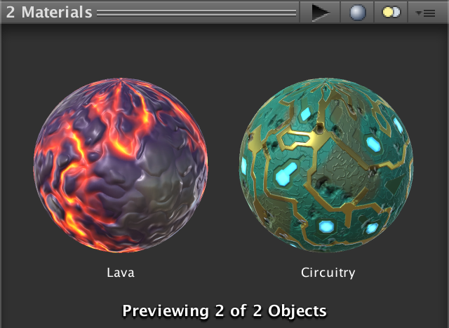
Editing Multiple Materials
So far, we've only considered editing a single material at a time. But Unity allows us to have multiple materials selected. If those materials all use our shader, then the shader GUI can be used to edit all of them at once. You'll also see the entire selection in the preview panel.
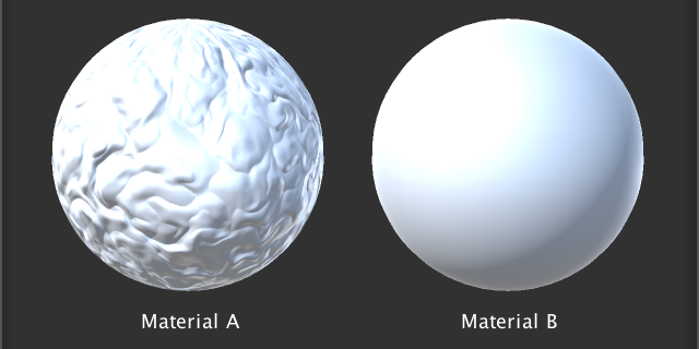
Setting Too Few Keywords
So editing multiple materials at the same time already works! However, there is a problem. You'll see this when creating two new materials that use our shader. Select both, then assign a normal map to them. Even though both materials now have a normal map, only the first material ends up using them.
This happens because our shader gui only sets the keyword of one material. This is the editor's target, which is the first material in the selection.
We can solve this problem by adjusting the keywords of all materials in the selection. To do this, we have to adjust our shader GUI's SetKeyword method. Instead of using the target field, we have to iterate through all the material in the editor's targets array. Let's use a foreach loop to do this, as it's concise code, and we don't need to worry about performance here.
	void SetKeyword (string keyword, bool state) {
		if (state) {
			foreach (Material m in editor.targets) {
				m.EnableKeyword(keyword);
			}
		}
		else {
			foreach (Material m in editor.targets) {
				m.DisableKeyword(keyword);
			}
		}
	}
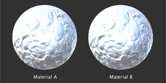
With this change, the normals will show up in all materials, after changing the map or the bump scale.
Setting Too Many Keywords
Unfortunately, we just created another problem. Consider a selection of two materials. The first material uses a normal map, while the second does not. In this case, the bump scale is shown by the UI, because that is based on the first material. This is not a problem, as the second material will just ignore the bump scale. However, when the bump scale is changed, the UI will update the keywords of both materials. The result will be that both materials have the _NORMAL_MAP keyword set. So the second material ends up with the _NORMAL_MAP keyword enabled, even though it doesn't use a normal map!
This problem wouldn't exist if we only updated the keywords when the texture property is changed. Unfortunately, because TexturePropertySingleLine combines two properties, we cannot distinguish between them with the BeginChangeCheck and EndChangeCheck methods. This was fine before, but no longer.
To fix this problem, we have to keep track of the map's texture reference before it can be changed. Then we only set the keyword if a change was made, and it's the map that's different.
	void DoNormals () {
		MaterialProperty map = FindProperty("_NormalMap");
		Texture tex = map.textureValue;
		EditorGUI.BeginChangeCheck();
		editor.TexturePropertySingleLine(
			MakeLabel(map), map,
			tex ? FindProperty("_BumpScale") : null
		);
		if (EditorGUI.EndChangeCheck() && tex != map.textureValue) {
			SetKeyword("_NORMAL_MAP", map.textureValue);
		}
	}
This solves the problem for DoNormals. But it also affects DoMetallic, DoOcclusion, DoEmission, and DoSecondaryNormals. Adjust all these methods like we fixed DoNormals. Now our shader GUI properly supports multi-material editing!
The next tutorial is Transparency.