Rendering 18
Realtime GI, Probe Volumes, LOD Groups
- Support Realtime Global Illumination.
- Animate emissive light contribution to GI.
- Work with light probe proxy volumes.
- Use LOD groups in combination with GI.
- Cross-fade between LOD levels.
This is part 18 of a tutorial series about rendering. After wrapping up baked global illumination in part 17, we move on to supporting realtime GI. After that, we'll also support light probe proxy volumes and cross-fading LOD groups.
From now on, this tutorial series is made with Unity 2017.1.0f3. It won't work with older versions, because we'll end up using a new shader function.
Realtime Global Illumination
Baking light works very well for static geometry, and also pretty well for dynamic geometry thanks to light probes. However, it cannot deal with dynamic lights. Lights in mixed mode can get away with some realtime adjustments, but too much makes it obvious that the baked indirect light doesn't change. So when you have an outdoor scene, the sun has to be unchanging. It cannot travel across the sky like it does in real life, as it requires gradually changing GI. So the scene has to be frozen in time.
To make indirect lighting work with something like a moving sun, Unity uses the Enlighten system to calculate realtime global illumination. It works like baked indirect lighting, except that the lightmaps and probes are computed at runtime.
Figuring out indirect light requires knowledge of how light could bounce between static surfaces. The question is which surfaces are potentially affected by which other surfaces, and to what degree. Figuring out these relationships is a lot of work and cannot be done in realtime. So this data is processed by the editor and stored for use at runtime. Enlighten then uses it to compute the realtime lightmaps and probe data. Even then, it's only feasible with low resolution lightmaps.
Enabling Realtime GI
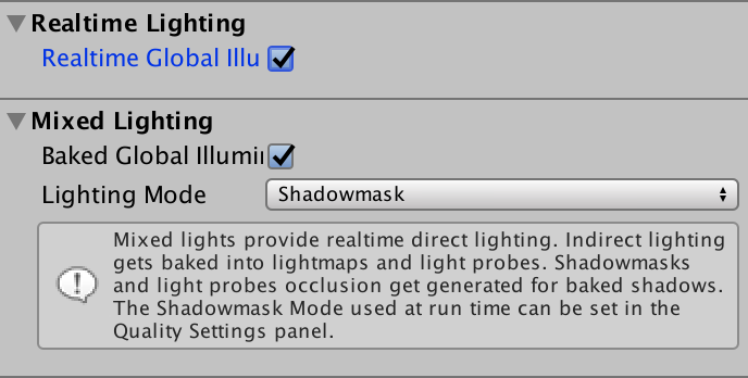
Realtime global illumination can be enabled independent of baked lighting. You can have none, one, or both active at the same time. It is enabled via the checkbox in the Realtime Lighting section of the Lighting window.
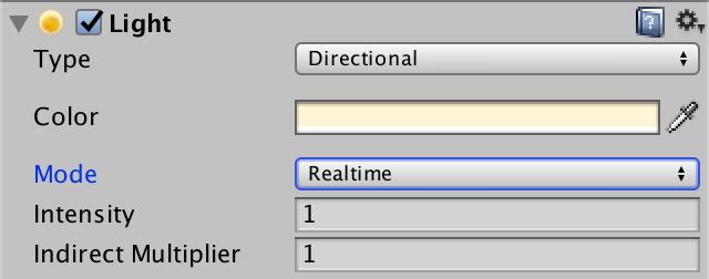
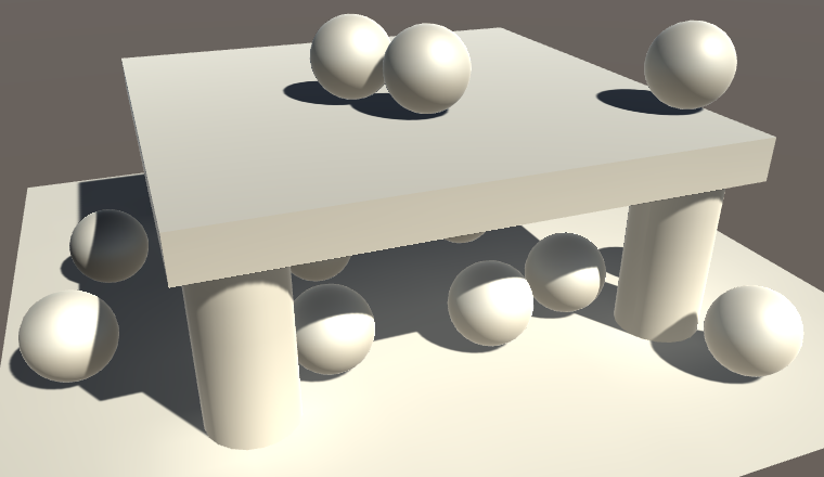
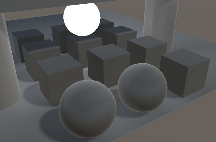
To see realtime GI in action, set the mode of the main light in our test scene to realtime. As we have no other lights, this effectively turns off baked lighting, even when it is enabled.
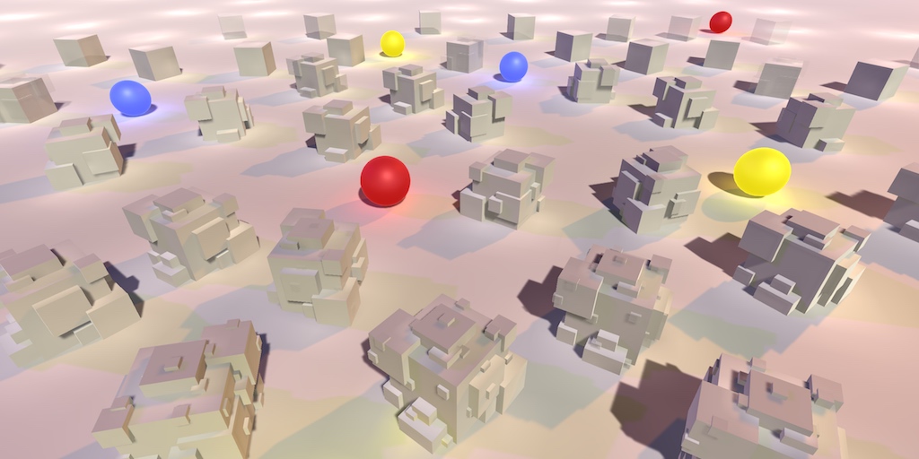
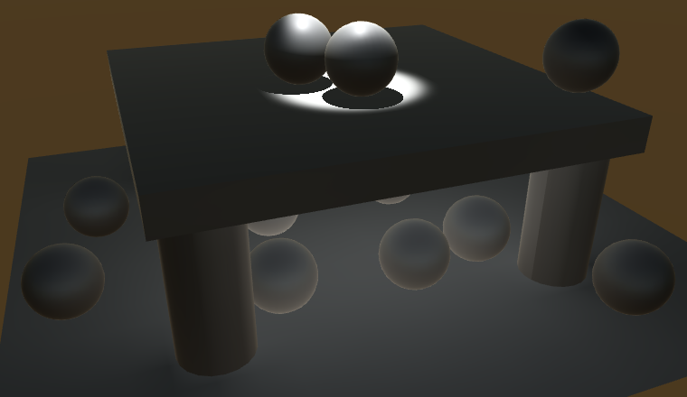
Make sure that all objects in the scene use our white material. Like last time, the spheres are all dynamic and everything else is static geometry.
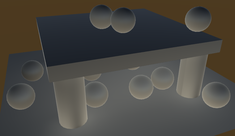
It turns out that only the dynamic objects benefit from realtime GI. The static objects have become darker. That's because the light probes automatically incorporated the realtime GI. Static objects have to sample the realtime lightmaps, which are not the same as the baked lightmaps. Our shader doesn't do this yet.
Baking Realtime GI
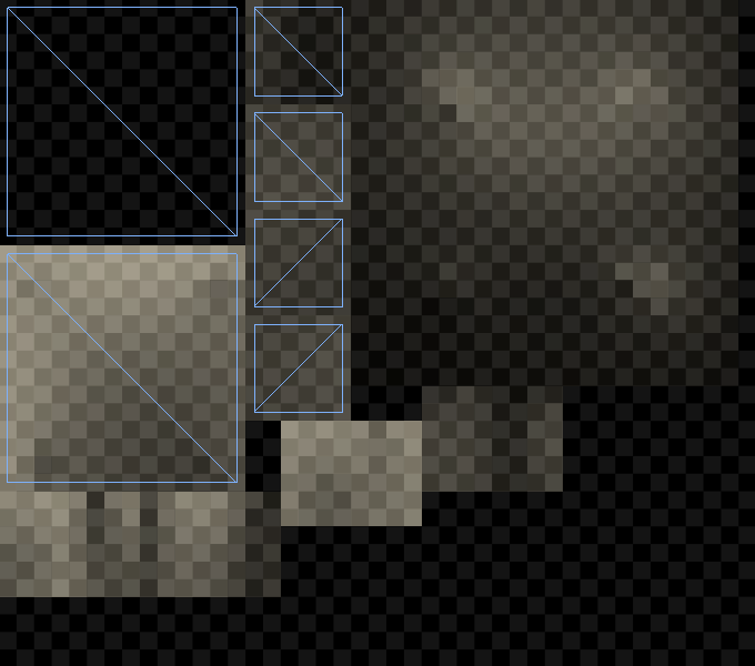
Unity already generates the realtime lightmaps while in edit mode, so you can always see the realtime GI contribution. These maps are not retained when switching between edit and play mode, but they end up the same. You can inspect the realtime lightmaps via the Object maps tab of the Lighting window, with a lightmap-static object selected. Choose the Realtime Intensity visualization to see the realtime lightmap data.
Although realtime lightmaps are already baked, and they might appear correct, our meta pass actually uses the wrong coordinates. Realtime GI has its own lightmap coordinates, which can end up being different than those for static lightmaps. Unity generates these coordinates automatically, based on the lightmap and object settings. They are stored in the third mesh UV channel. So add this data to VertexData in My Lightmapping.
struct VertexData {
	float4 vertex : POSITION;
	float2 uv : TEXCOORD0;
	float2 uv1 : TEXCOORD1;
	float2 uv2 : TEXCOORD2;
};
Now MyLightmappingVertexProgram has to use either the second or third UV set, together with either the static or dynamic lightmap's scale and offset. We can rely on the UnityMetaVertexPosition function to use the right data.
Interpolators MyLightmappingVertexProgram (VertexData v) {
	Interpolators i;
//	v.vertex.xy = v.uv1 * unity_LightmapST.xy + unity_LightmapST.zw;
//	v.vertex.z = v.vertex.z > 0 ? 0.0001 : 0;
//
//	i.pos = UnityObjectToClipPos(v.vertex);
	i.pos = UnityMetaVertexPosition(
		v.vertex, v.uv1, v.uv2, unity_LightmapST, unity_DynamicLightmapST
	);

	i.uv.xy = TRANSFORM_TEX(v.uv, _MainTex);
	i.uv.zw = TRANSFORM_TEX(v.uv, _DetailTex);
	return i;
}
Note that the meta pass is used for both baked and realtime lightmapping. So when realtime GI is used, it will also be included in builds.
Sampling Realtime Lightmaps
To actually sample the realtime lightmaps, we have to also add the third UV set to VertexData in My Lighting.
struct VertexData {
	float4 vertex : POSITION;
	float3 normal : NORMAL;
	float4 tangent : TANGENT;
	float2 uv : TEXCOORD0;
	float2 uv1 : TEXCOORD1;
	float2 uv2 : TEXCOORD2;
};
When a realtime lightmap is used, we have to add its lightmap coordinates to our interpolators. The standard shader combines both lightmap coordinate sets in a single interpolator – multiplexed with some other data – but we can get away with separate interpolators for both. We know that there is dynamic light data when the DYNAMICLIGHTMAP_ON keyword is defined. It's part of the keyword list of the multi_compile_fwdbase compiler directive.
struct Interpolators {
	…

	#if defined(DYNAMICLIGHTMAP_ON)
		float2 dynamicLightmapUV : TEXCOORD7;
	#endif
};
Fill the coordinates just like the static lightmap coordinates, except with the dynamic lightmap's scale and offset, made available via unity_DynamicLightmapST.
Interpolators MyVertexProgram (VertexData v) {
	…

	#if defined(LIGHTMAP_ON) || ADDITIONAL_MASKED_DIRECTIONAL_SHADOWS
		i.lightmapUV = v.uv1 * unity_LightmapST.xy + unity_LightmapST.zw;
	#endif

	#if defined(DYNAMICLIGHTMAP_ON)
		i.dynamicLightmapUV =
			v.uv2 * unity_DynamicLightmapST.xy + unity_DynamicLightmapST.zw;
	#endif

	…
}
Sampling the realtime lightmap is done in our CreateIndirectLight function. Duplicate the #if defined(LIGHTMAP_ON) code block and make a few changes. First, the new block is based on the DYNAMICLIGHTMAP_ON keyword. Also, it should use DecodeRealtimeLightmap instead of DecodeLightmap, because the realtime maps use a different color format. Because this data might be added to baked lighting, don't immediately assign to indirectLight.diffuse, but use an intermediate variable which is added to it at the end. Finally, we should only sample spherical harmonics when neither a baked nor a realtime lightmap is used.
#if defined(LIGHTMAP_ON) indirectLight.diffuse = DecodeLightmap(UNITY_SAMPLE_TEX2D(unity_Lightmap, i.lightmapUV)); #if defined(DIRLIGHTMAP_COMBINED) float4 lightmapDirection = UNITY_SAMPLE_TEX2D_SAMPLER( unity_LightmapInd, unity_Lightmap, i.lightmapUV ); indirectLight.diffuse = DecodeDirectionalLightmap( indirectLight.diffuse, lightmapDirection, i.normal ); #endif ApplySubtractiveLighting(i, indirectLight);// #else// indirectLight.diffuse += max(0, ShadeSH9(float4(i.normal, 1)));#endif #if defined(DYNAMICLIGHTMAP_ON) float3 dynamicLightDiffuse = DecodeRealtimeLightmap( UNITY_SAMPLE_TEX2D(unity_DynamicLightmap, i.dynamicLightmapUV) ); #if defined(DIRLIGHTMAP_COMBINED) float4 dynamicLightmapDirection = UNITY_SAMPLE_TEX2D_SAMPLER( unity_DynamicDirectionality, unity_DynamicLightmap, i.dynamicLightmapUV ); indirectLight.diffuse += DecodeDirectionalLightmap( dynamicLightDiffuse, dynamicLightmapDirection, i.normal ); #else indirectLight.diffuse += dynamicLightDiffuse; #endif #endif #if !defined(LIGHTMAP_ON) && !defined(DYNAMICLIGHTMAP_ON) indirectLight.diffuse += max(0, ShadeSH9(float4(i.normal, 1))); #endif
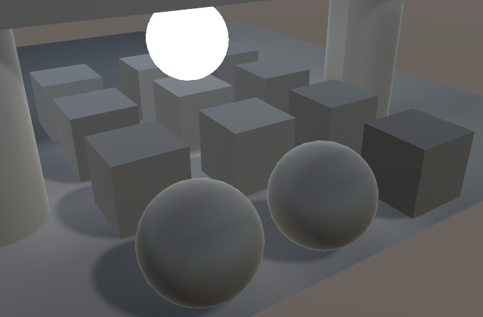
Now realtime lightmaps are used by our shader. Initially, it might look the same as baked lighting with a mixed light, when using distance shadowmask mode. The difference becomes obvious when turning off the light while in play mode.
After disabling a mixed light, its indirect light will remain. In contrast, the indirect contribution of a realtime light disappears – and reappears – as it should. However, it might take a while before the new situation is fully baked. Enlighten incrementally adjust the lightmaps and probes. How quickly this happens depends on the complexity of the scene and the Realtime Global Illumination CPU quality tier setting.
All realtime lights contribute to realtime GI. However, its typical use is with the main direction light only, representing the sun as it moves through the sky. It is fully functional for directional lights. Points lights and spotlights work too, but only unshadowed. So when using shadowed point lights or spotlights you can end up with incorrect indirect lighting.
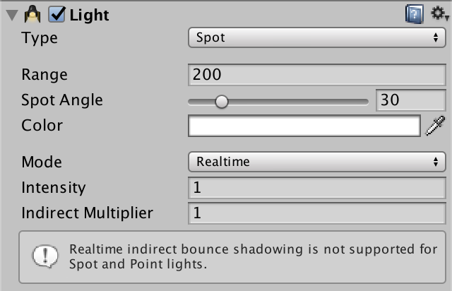
If you want to exclude a realtime light from realtime GI, you can do so by settings its Indirect Multiplier for its light intensity to zero.
Emissive Light
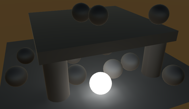
Realtime GI can also be used for static objects that emit light. This makes it possible to vary their emission with matching realtime indirect light. Let's try this out. Add a static sphere to the scene and give it a material that uses our shader with a black albedo and white emission color. Initially, we can only see the indirect effects of the emitted light via the static lightmaps.
To bake emissive light into the static lightmap, we had to set the material's global illumination flags in our shader GUI. As we always set the flags to BakedEmissive, the light ends up in the baked lightmap. This is fine when the emissive light is constant, but doesn't allow us to animate it.
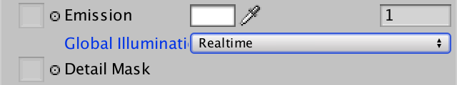
To support both baked and realtime lighting for the emission, we have to make this configurable. We can do so by adding a choice for this to MyLightingShaderGUI, via the MaterialEditor.LightmapEmissionProperty method. Its single parameter is the property's indentation level.
	void DoEmission () {
		MaterialProperty map = FindProperty("_EmissionMap");
		Texture tex = map.textureValue;
		EditorGUI.BeginChangeCheck();
		editor.TexturePropertyWithHDRColor(
			MakeLabel(map, "Emission (RGB)"), map, FindProperty("_Emission"),
			emissionConfig, false
		);
		editor.LightmapEmissionProperty(2);
		if (EditorGUI.EndChangeCheck()) {
			if (tex != map.textureValue) {
				SetKeyword("_EMISSION_MAP", map.textureValue);
			}

			foreach (Material m in editor.targets) {
				m.globalIlluminationFlags =
					MaterialGlobalIlluminationFlags.BakedEmissive;
			}
		}
	}
We also have to stop overriding the flags each time an emission property has changed. Actually, it is a bit more complicated than that. One of the flag options is EmissiveIsBlack, which indicates that computation of the emission can be skipped. This flag is always set for new materials. To make indirect emission work, we have to guarantee that this flag is not set, regardless whether we choose realtime or baked. We can do this by always masking the EmissiveIsBlack bit of the flags value.
			foreach (Material m in editor.targets) {
				m.globalIlluminationFlags &=
					~MaterialGlobalIlluminationFlags.EmissiveIsBlack;
			}
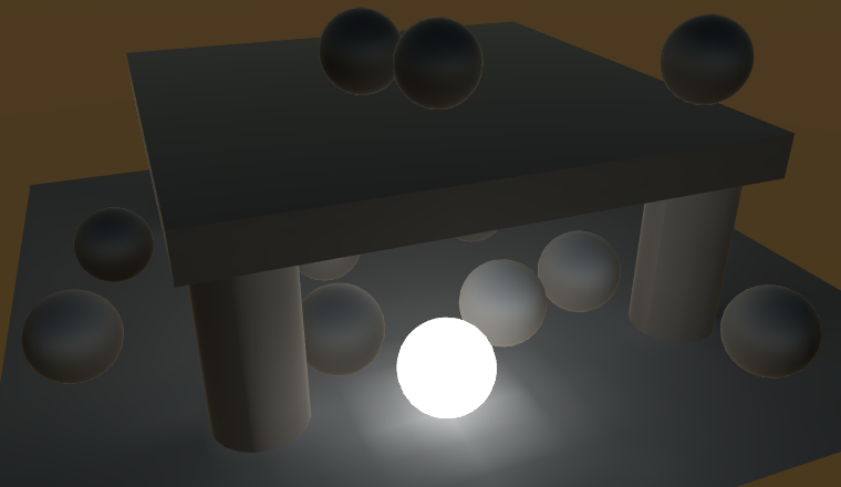
The visual difference between baked and realtime GI is that the realtime lightmap usually has a much lower resolution than the baked one. So when the emission doesn't change and you use baked GI anyway, make sure to take advantage of its higher resolution.
Animating Emission
Realtime GI for emission is only possible for static objects. While the objects are static, the emission properties of their materials can be animated and will be picked up by the global illumination system. Let's try this out with a simple component that oscillates between a white and black emission color.
using UnityEngine;

public class EmissiveOscillator : MonoBehaviour {

	Material emissiveMaterial;

	void Start () {
		emissiveMaterial = GetComponent<MeshRenderer>().material;
	}

	void Update () {
		Color c = Color.Lerp(
			Color.white, Color.black,
			Mathf.Sin(Time.time * Mathf.PI) * 0.5f + 0.5f
		);
		emissiveMaterial.SetColor("_Emission", c);
	}
}
Add this component to our emissive sphere. When in play mode, its emission will animate, but indirect light isn't affected yet. We have to notify the realtime GI system that it has work to do. This can be done by invoking the Renderer.UpdateGIMaterials method of the appropriate mesh renderer.
	MeshRenderer emissiveRenderer;
	Material emissiveMaterial;

	void Start () {
		emissiveRenderer = GetComponent<MeshRenderer>();
		emissiveMaterial = emissiveRenderer.material;
	}

	void Update () {
		…
		emissiveMaterial.SetColor("_Emission", c);
		emissiveRenderer.UpdateGIMaterials();
	}
Invoking UpdateGIMaterials triggers a complete update of the object's emission, rendering it using its meta pass. This is necessary when the emission is more complex than a solid color, for example if we used a texture. If a solid color is sufficient, we can get away with a shortcut by invoking DynamicGI.SetEmissive with the renderer and the emission color. This is quicker than rendering the object with the meta pass, so take advantage of it when able.
// emissiveRenderer.UpdateGIMaterials();DynamicGI.SetEmissive(emissiveRenderer, c);
Light Probe Proxy Volumes
Both baked and realtime GI is applied to dynamic objects via light probes. An object's position is used to interpolate light probe data, which is then used to apply GI. This works for fairly small objects, but is too crude for larger ones.
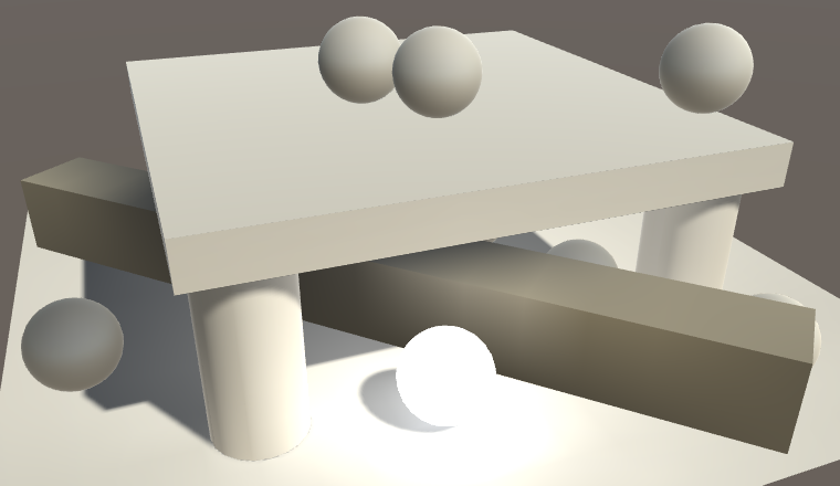
As an example, add long stretched cube to the test scene so that it is subject to varying lighting conditions. It should use our white material. As it is a dynamic cube, it ends up using a single point to determine its GI contribution. Positioning it so that this point ends up shadowed, the entire cube becomes dark, which is obviously wrong. To make it very obvious, use a baked main light, so all lighting comes from the baked and realtime GI data.
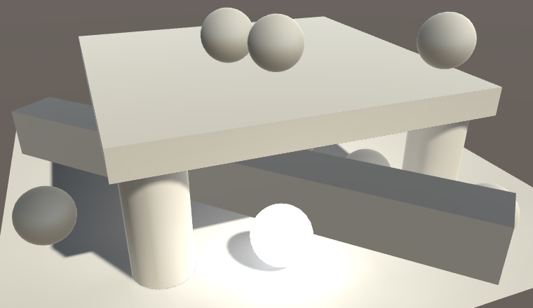
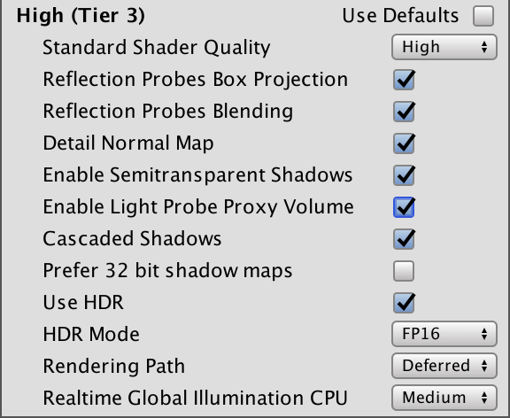
To make light probes work for cases like this, we can use a light probe proxy volume, or LPPV for short. This works by feeding the shader a grid of interpolated probe values, instead of a single one. This requires a floating-point 3D texture with linear filtering, which limits it to modern graphics cards. Besides that, also make sure that LPPV support is enabled in the graphics tier settings.
Adding an LPPV to an Object
An LPPV can be setup in various ways, the most straightforward is as a component of the object that will use it. You can add it via Component / Rendering / Light Probe Proxy Volume.
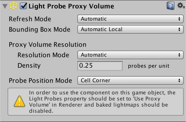
LPPVs work by interpolating between light probes at runtime, as if they were a grid of regular dynamic objects. The interpolated values are cached, with the Refresh Mode controlling when they are updated. The default is Automatic, which means that updates happen when the dynamic GI changes and when the probe group moves. Bounding Box Mode controls how the volume is positioned. Automatic Local means that it fits the bounding box of the object it's attached to. These default settings work well for our cube, so we'll keep them.
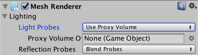
To have our cube actually use the LPPV, we have to set the Light Probes mode of its mesh renderer to Use Proxy Volume. The default behavior is to use the LPPV component of the object itself, but you could also force it to use another volume.
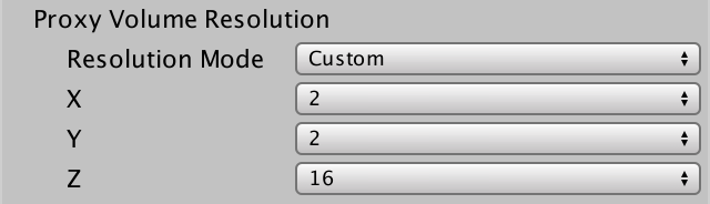
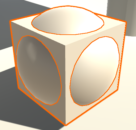
The automatic resolution mode doesn't work well for our stretched cube. So set the Resolution Mode to Custom and make sure that there are sample points at the cube corners and multiple along its long edges. You can see these sample points when you have the object selected.
Sampling the Volume
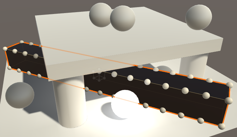
The cube has become black, because our shader doesn't support LPPV sampling yet. To make it work, we have to adjust the spherical harmonics code inside our CreateIndirectLight function. When an LPPV is used, UNITY_LIGHT_PROBE_PROXY_VOLUME is defined as 1. Let's do nothing in that case and see what happens.
		#if !defined(LIGHTMAP_ON) && !defined(DYNAMICLIGHTMAP_ON)
			#if UNITY_LIGHT_PROBE_PROXY_VOLUME
			#else
				indirectLight.diffuse += max(0, ShadeSH9(float4(i.normal, 1)));
			#endif
		#endif
It turns out that all spherical harmonics are disabled, also for dynamic objects that don't use LPPVs. That's because UNITY_LIGHT_PROBE_PROXY_VOLUME is defined project-wide, not per object instance. Whether an individual object uses an LPPV is indicated by the X component of unity_ProbeVolumeParams, defined in UnityShaderVariables. If it is set to 1, then we have an LPPV, otherwise we should use regular spherical harmonics.
			#if UNITY_LIGHT_PROBE_PROXY_VOLUME
				if (unity_ProbeVolumeParams.x == 1) {
				}
				else {
					indirectLight.diffuse +=
						max(0, ShadeSH9(float4(i.normal, 1)));
				}
			#else
				indirectLight.diffuse += max(0, ShadeSH9(float4(i.normal, 1)));
			#endif
To sample the volume, we can use the SHEvalLinearL0L1_SampleProbeVolume function instead of ShadeSH9. This function is defined in UnityCG and requires the world position as an extra parameter.
				if (unity_ProbeVolumeParams.x == 1) {
					indirectLight.diffuse = SHEvalLinearL0L1_SampleProbeVolume(
						float4(i.normal, 1), i.worldPos
					);
					indirectLight.diffuse = max(0, indirectLight.diffuse);
				}
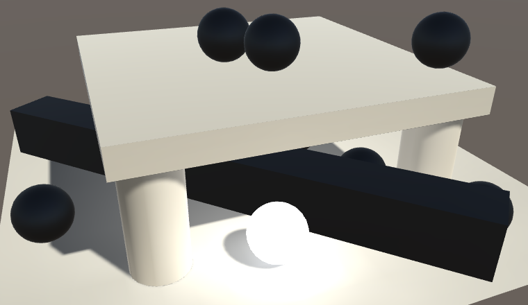
Our shader now samples the LPPV when needed, but the result is too dark. At least, that is the case when working in gamma color space. That's because the spherical harmonics data is stored in linear space. So a color conversion might be required.
				if (unity_ProbeVolumeParams.x == 1) {
					indirectLight.diffuse = SHEvalLinearL0L1_SampleProbeVolume(
						float4(i.normal, 1), i.worldPos
					);
					indirectLight.diffuse = max(0, indirectLight.diffuse);
					#if defined(UNITY_COLORSPACE_GAMMA)
			            indirectLight.diffuse =
			            	LinearToGammaSpace(indirectLight.diffuse);
			        #endif
				}
LOD Groups
When an object ends up covering only a small portion of the app's window, you don't need a highly detailed mesh to render it. You can use different meshes depending on the view size of the object. This is known as level of detail, or LOD for short. Unity allows us to do this via the LOD Group component.
Creating a LOD Hierarchy
The idea is that you use multiple version of the same mesh at various detail levels. The highest level – LOD 0 – has the most vertices, sub-objects, animations, complex materials, and so on. Additional levels become progressively simpler and cheaper to render. Ideally, adjacent LOD levels are designed so that you can't easily tell the difference between them when Unity switches from one to the other. Otherwise the sudden change would be glaring. But while investigating this technique we'll use obviously different meshes.
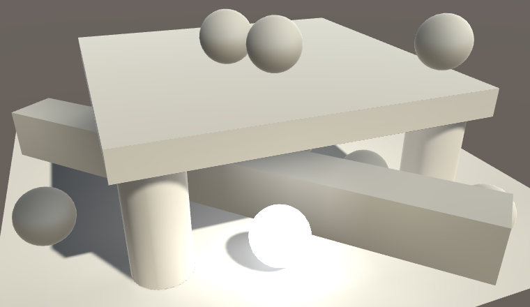
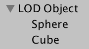
Create an empty game object and give it two children. The first is a standard sphere and the second is a standard cube with its scale set to 0.75 uniformly. The result looks like and overlapping sphere and cube, as expected.
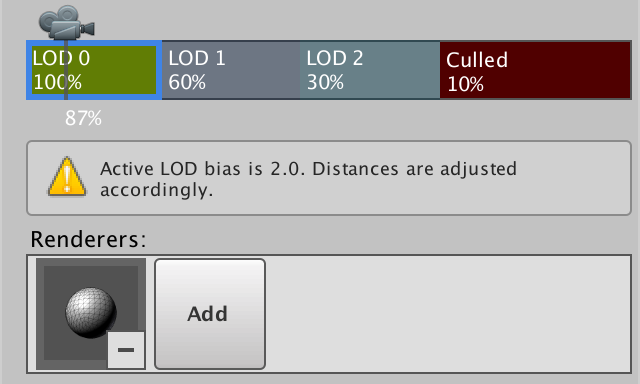
Add a LOD group component to the parent object, via Component / Rendering / LOD Group. You'll get a LOD group with default settings, which has three LOD levels. The percentages refer to the vertical portion of the window covered by the object's bounding box. So the default is to switch to LOD 1 when the vertical size drops down to 60% of the window's height, and to LOD 2 when it is reduced to 30%. When it reaches 10% it isn't rendered at all. You can change these thresholds by dragging the edges of the LOD boxes.
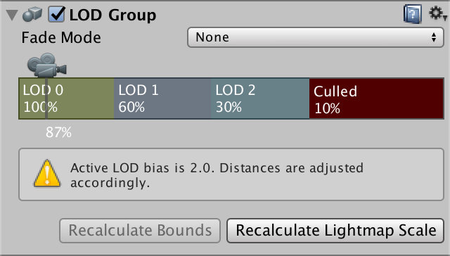
The thresholds are modified by the LOD Bias, which is mentioned by the component's inspector. This is a quality settings with a default value of 2, which means that the thresholds are effectively halved. It is also possible to set a maximum LOD level, which results in the highest levels being skipped.
To makes it work, you have to tell the component which objects to use per LOD level. This is done by selecting a LOD block and adding objects to its Renderers list. While you could add any object in the scene, by sure to add its child objects. Use the sphere for LOD 0 and the cube for LOD 1. We'll leave LOD 2 empty, so we effectively only have two LOD levels. If you want to, you can delete and insert LOD levels via the right-click context menu.
Once the LOD levels are configured, you can see them in action by moving the camera. If the object ends up big enough, it'll use the sphere, otherwise it will use the cube or won't be rendered at all.
Baked GI and LOD Groups
Because how a LOD group is rendered depends on its view size, they are naturally dynamic. However, you can still make them static. Do this for the entire object hierarchy, so both the root and its two children. Then set the main light to baked to see what happens.
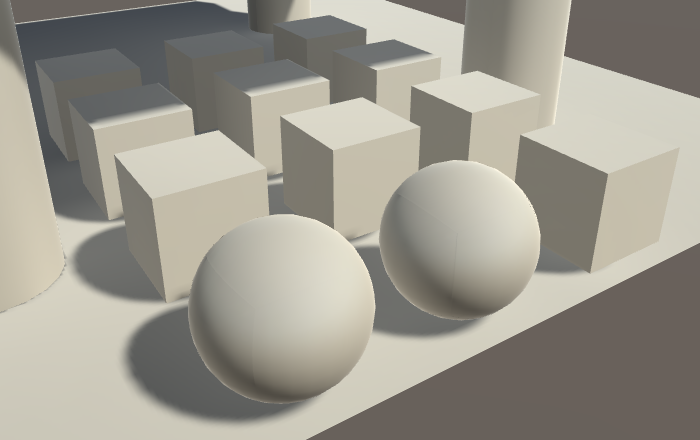
It looks like LOD 0 is used when baking static lightmaps. We end up always seeing the sphere's shadow and indirect light contribution, even when the LOD group switches to a cube or culls itself. But note that the cube uses the static lightmap as well. So it doesn't use light probes, right? Turn of the light probe group to find out.
Disabling the probe group made the cubes darker. This means that that they no longer receive indirect light. This happens because LOD 0 is used when determining indirect light during the baking process. To find the indirect light for the other LOD levels, the best Unity can do is rely on the baked light probes. So we need light probes to get indirect light baked for our cubes, even if we don't need light probes at runtime.
Realtime GI and LOD Groups
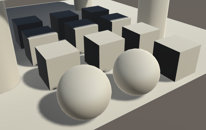
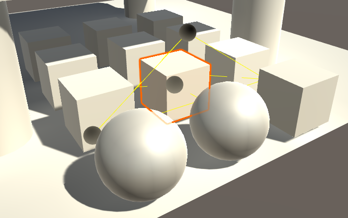
When only using realtime GI, the approach is similar, except that our cube now uses the light probes at runtime. You can verify this by selecting the sphere or the cube. When the cube is selected, you can see the gizmos that show which light probes are used. The sphere doesn't show them, because it uses the dynamic lightmap.
It gets more complicated when both baked and realtime GI are used at the same time. In that case, the cube should use lightmaps for the baked GI and light probes for the realtime GI. Unfortunately this is not possible, because lightmaps and spherical harmonics cannot be used at the same time. it's either one or the other. Because lightmap data is available for the cube, Unity ends up using that. Consequently, the cube isn't affected by realtime GI.
An important detail is that the baking and rendering of LOD levels is completely independent. They don't need to use the same settings. If realtime GI ends up more important than baked GI, you can force the cube to use light probes by making sure that it is not lightmap-static, while keeping the sphere static.
Cross-fading Between LOD Levels
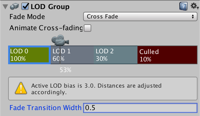
A downside of LOD groups is that it can be visually obvious when the LOD level changes. Geometry suddenly pops into view, disappears, or changes shape. This can be mitigated by cross-fading between adjacent LOD levels, which is done by setting the group's Fade Mode to Cross Fade. There is also another fade mode, used by Unity for SpeedTree objects, which we won't use.
When cross-fading is enabled, each LOD level shows a Fade Transition Width field that controls which portion of its block is used for fading. For example, when set to 0.5 half the LOD's range is used to fade to the next level. Alternatively, the fading can be animated, in which case it takes about half a second to transition between LOD levels.
When cross-fading is enabled, two LOD levels are rendered at the same time while the group is transitioning between them.
Supporting Cross-fading
Unity's standard shader doesn't support cross-fading by default. You'd have to copy the standard shader and add a multi-compile directive for the LOD_FADE_CROSSFADE keyword. We need to add that directive as well to support cross-fading with My First Lighting Shader. Add the directive to all passes except the meta pass.
#pragma multi_compile _ LOD_FADE_CROSSFADE
We'll use dithering to transition between the LOD levels. That approach works with both forward and deferred rendering, and also with shadows.
We've already used dithering, when creating semitransparent shadows. It required the fragment's screen-space coordinates, which forced us to use different interpolator structures for the vertex and fragment program. So let's duplicate the Interpolators structure in My Lighting as well, renaming one to InterpolatorsVertex.
struct InterpolatorsVertex {
	…
};

struct Interpolators {
	…
};

…

InterpolatorsVertex MyVertexProgram (VertexData v) {
	InterpolatorsVertex i;
	…
}
The interpolators for the fragment program have to contain vpos when we have to cross-fade, otherwise we can keep the usual position.
struct Interpolators {
	#if defined(LOD_FADE_CROSSFADE)
		UNITY_VPOS_TYPE vpos : VPOS;
	#else
		float4 pos : SV_POSITION;
	#endif

	…
};
We can perform the cross-fading by using the UnityApplyDitherCrossFade function at the start of our fragment program.
FragmentOutput MyFragmentProgram (Interpolators i) {
	#if defined(LOD_FADE_CROSSFADE)
		UnityApplyDitherCrossFade(i.vpos);
	#endif

	…
}
Crossfading now works for geometry. To make it work for shadows as well, we have to adjust My Shadows. First, vpos has to be used when we're cross-fading. Second, we also have to use UnityApplyDitherCrossFade at the start of the fragment program.
struct Interpolators {
	#if SHADOWS_SEMITRANSPARENT || defined(LOD_FADE_CROSSFADE)
		UNITY_VPOS_TYPE vpos : VPOS;
	#else
		float4 positions : SV_POSITION;
	#endif

	…
};

…

float4 MyShadowFragmentProgram (Interpolators i) : SV_TARGET {
	#if defined(LOD_FADE_CROSSFADE)
		UnityApplyDitherCrossFade(i.vpos);
	#endif

	…
}
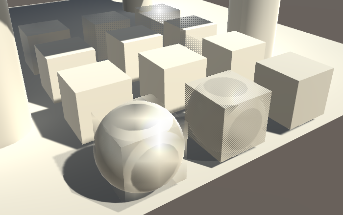
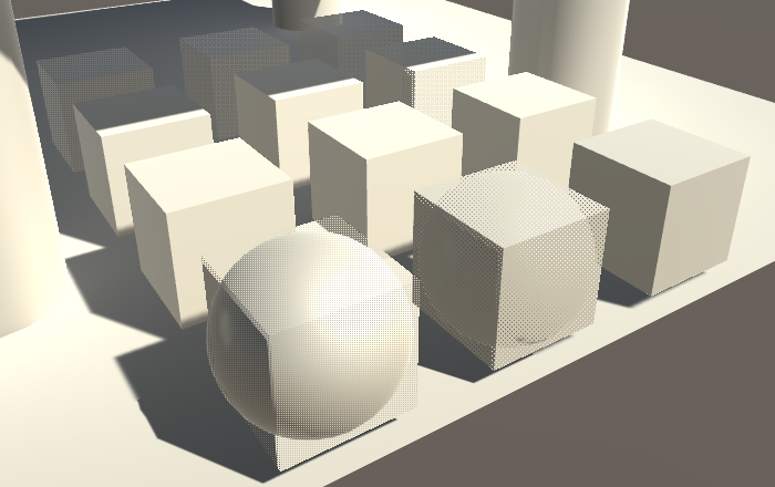
Because the cube and sphere intersect each other, we get some strange self-shadowing while cross-fading between them. This is handy to see that cross-fading between shadows works, but you have to watch out for such artifacts when creating LOD geometry for actual games.
The next tutorial is GPU Instancing.