Modified Grid
Sharing and Shading
- Create a grid variant with shared vertices.
- Make a shader that modifies vertex data.
- Apply a rippling animation to the grid.
This is the third tutorial in a series about procedural meshes. It introduces a second way to generate a square grid and a way to animate it via a shader.
This tutorial is made with Unity 2020.3.23f1.
Sharing All Vertices
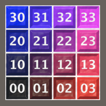
The grid that we have generated in the previous tutorial is made of independent quads. Each quad consists of two triangles that share two vertices, but adjacent quads do not share vertices. This allows each quad to have its own texture coordinates. In our case they all cover the full 0–1 range, but this need not be so. Each quad could have different texture coordinates, which could be used to for example show different parts of a texture, potentially with different scales and orientations as well.
However, in many cases there is no need for independent quads. Typically a single texture gets applied to the entire grid. In such cases we can drastically reduce the vertex count and thus the size of the mesh by having quads share vertices with their neighbors.
Shared Grid Variant
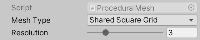
We're going to support a vertex-sharing variant of SquareGrid. Begin by duplicating it and renaming the new version to SharedSquareGrid, leaving all other code the same for now.
public struct SharedSquareGrid : IMeshGenerator { … }
To allow selection of the variants via the inspector we'll use the same approach that we used in the Pseudorandom Noise series: an array of job-scheduling delegates. Define a MeshJobScheduleDelegate delegate type for this, matching the signature of MeshJob.ScheduleParallel. As it belongs with MeshJob let's put it in the same asset file, but outside the generic MeshJob type.
	public struct MeshJob<G, S> : IJobFor
		where G : struct, IMeshGenerator
		where S : struct, IMeshStreams { … }

	public delegate JobHandle MeshJobScheduleDelegate (
		Mesh mesh, Mesh.MeshData meshData, int resolution, JobHandle dependency
	);
Now we can add a static jobs array to ProceduralMesh containing scheduling delegates for SquareGrid and SharedSquareGrid jobs, along with an enum type and field to select the mesh type that we want to generate via the inspector.
public class ProceduralMesh : MonoBehaviour {

	static MeshJobScheduleDelegate[] jobs = {
		MeshJob<SquareGrid, SingleStream>.ScheduleParallel,
		MeshJob<SharedSquareGrid, SingleStream>.ScheduleParallel
	};

	public enum MeshType {
		SquareGrid€, SharedSquareGrid€
	};

	[SerializeField]
	MeshType meshType;

	…
}
Adjust GenerateMesh so it runs the desired job.
//MeshJob<SquareGrid, SingleStream>.ScheduleParallel(// mesh, meshData, resolution, default//).Complete();jobs[(int)meshType](mesh, meshData, resolution, default).Complete();
Rows of Vertices
Now we're going to adjust SharedSquareGrid so it indeed shares the vertices of the quads. This requires a change of approach, primarily focused on vertices instead of quads.
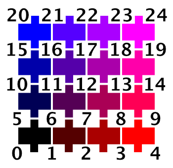
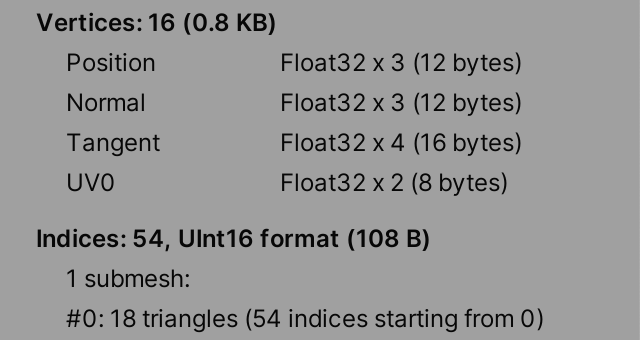
Each row of vertices for a resolution R grid has R + 1 vertices. So the vertex count becomes that squared. Thus a resolution 4 shared grid would have 25 vertices, while a non-shared grid would require 64 vertices. Adjust the VertexCount property accordingly.
public int VertexCount => (Resolution + 1) * (Resolution + 1);
Also, our vertex-based approach will process rows of vertices instead of rows of quads, so JobLength has to increase by one.
public int JobLength => Resolution + 1;
Now remove the quad-based code from Execute and start fresh. The first step is to determine the index of the first vertex of the row, which is equal to the resolution plus one, multiplied with the row index.
		public void Execute<S> (int z, S streams) where S : struct, IMeshStreams {
			int vi = (Resolution + 1) * z;
		}
Next, we initialize a vertex variable with the constant normal and tangent vectors.
			int vi = (Resolution + 1) * z;

			var vertex = new Vertex();
			vertex.normal.y = 1f;
			vertex.tangent.xw = float2(1f, -1f);
Then we set the first—the leftmost—vertex of the row. Its position's X coordinate is always −0.5 and its Z coordinate is equal to the row's Z divided by the resolution, minus 0.5.
			vertex.tangent.xw = float2(1f, -1f);

			vertex.position.x = -0.5f;
			vertex.position.z = (float)z / Resolution - 0.5f;
			streams.SetVertex(vi, vertex);
Because all vertices are shared the texture coordinates have to be continuous across the entire grid. It makes the most sense to stretch the 0—1 domain across the entire grid, so we'll do that. Thus the texture U coordinate is zero for the first vertex and its V coordinate is equal to the row's Z divided by the resolution. So the texture coordinates are equal to the XZ position without the negative offset.
			vertex.position.z = (float)z / Resolution - 0.5f;
			vertex.texCoord0.y = (float)z / Resolution;
			streams.SetVertex(vi, vertex);
Once we have set the first vertex of the row we increment the vertex index and then follow with a loop over all other vertices of the row. This is done via a for loop that starts at 1 and continues until the resolution inclusive—as we have resolution plus one vertices per row—also incrementing the vertex index each iteration.
			streams.SetVertex(vi, vertex);
			vi += 1;

			for (int x = 1; x <= Resolution; x++, vi++) {}
Each iteration we only have to adjust the X position and U the texture coordinate and set the vertex. The Z positions and V texture coordinates are constant per row.
			for (int x = 1; x <= Resolution; x++, vi++) {
				vertex.position.x = (float)x / Resolution - 0.5f;
				vertex.texCoord0.x = (float)x / Resolution;
				streams.SetVertex(vi, vertex);
			}
Triangles
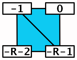
We also have to generate the triangles, again two per quad. We'll generate triangles for the vertices we've already set, so for the current vertex row and the one below it. This means that the first triangle index of a row is equal to the row index minus one, multiplied with double the resolution.
int vi = (Resolution + 1) * z, ti = 2 * Resolution * (z - 1);
Each iteration of the loop we have to set two triangles, just like for the non-shared grid. The difference is that in this case the triangle indices are shared and we make them relative to the top-right vertex index. So the vertex index offset for the top right vertex of the quad is zero, the top left is −1, the bottom right is the negative resolution minus 1, and the bottom left is the negative resolution minus 2.
			for (int x = 1; x <= Resolution; x++, vi++, ti += 2) {
				…

				streams.SetTriangle(
					ti + 0, vi + int3€(-Resolution - 2, -1, -Resolution - 1)
				);
				streams.SetTriangle(
					ti + 1, vi + int3€(-Resolution - 1, -1, 0)
				);
			}
But we must not generate quads for every vertex row, as there are no quads below the bottom one. Thus only do this if the row index is greater than zero.
				if (z > 0) {
					streams.SetTriangle(
						ti + 0, vi + int3€(-Resolution - 2, -1, -Resolution - 1)
					);
					streams.SetTriangle(
						ti + 1, vi + int3€(-Resolution - 1, -1, 0)
					);
				}
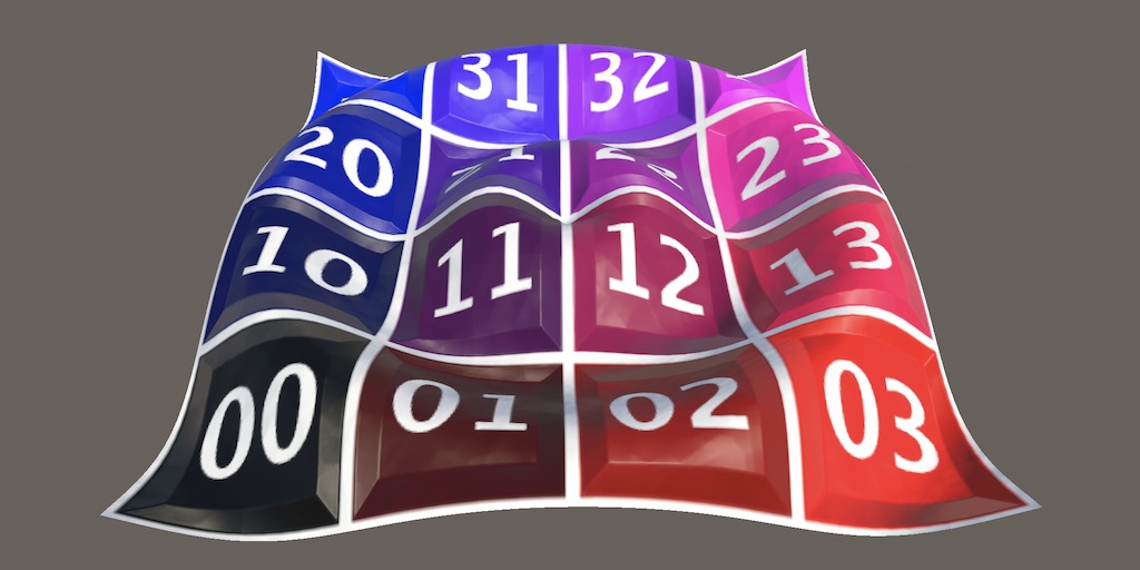
At this point we can generate a valid shared square grid.
Ripple Shader
Currently there is no visual difference between a resolution 1 and a resolution 10 shared square grid, both represent a flat plane. Without additional variety there is no reason to use a higher resolution. Grids like these are typically used to show uneven smooth surfaces, like terrain. The variety could be generated along with the mesh, but it can also be applied to a flat grid via a shader. As an example of this we'll make the grid ripple by letting the GPU adjust its vertices.
Shader Graph
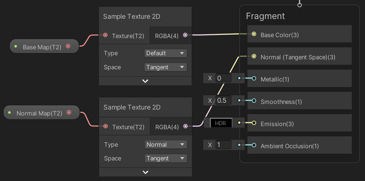
We'll create a Procedural Mesh shader graph that we'll use to visualize our mesh. To still apply the base map and the normal map add texture properties for them to the shader graph's blackboard.
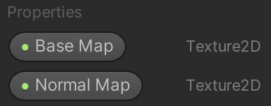
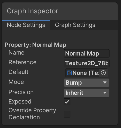
The normal map's Mode must be set to Bump to make it correctly provide a normal map, even when none is set. This can be done via the graph inspector, with the property selected.
Add the properties to the graph, along with two Sample Texture 2D nodes and connect them appropriately. The Type of the node that samples the normal map must be set to Normal.
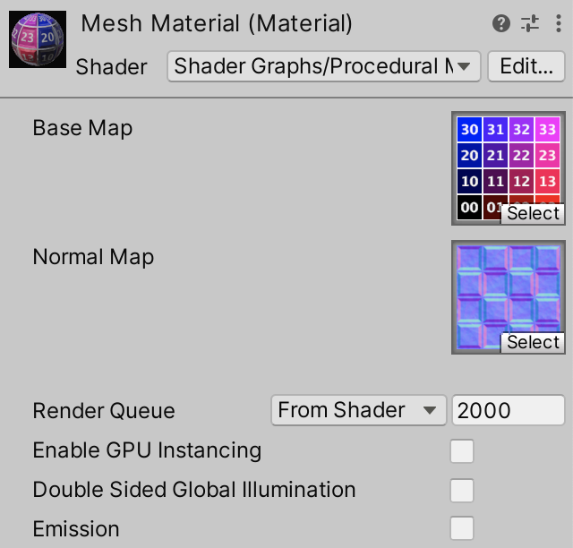
Adjust our material to use this shader graph instead of the default URP material.
You can also add properties for other setting like base color and smoothness, but I keep the configuration at a minimum.
Ripple Function
We'll use a ripple function similar to but simpler than the one we used in the Basics / Mathematical Surfaces tutorial: `y=asin(2pip(d-st))` where `d` is the distance to the wave origin, `a` is the wave amplitude, `p` is its period, `s` is its speed, and `t` is the time.
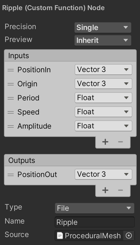
Although we could implement the function via shader graph nodes, it's easier to write code for it, so introcude a ProceduralMesh.hlsl asset file containing a Ripple_float function with the 3D input position, origin, period, speed, amplitude, and output position as parameters. Initially the output is simply the input position.
void Ripple_float (
	float3 PositionIn, float3 Origin,
	float Period, float Speed, float Amplitude,
	out float3 PositionOut
) {
	PositionOut = PositionIn;
}
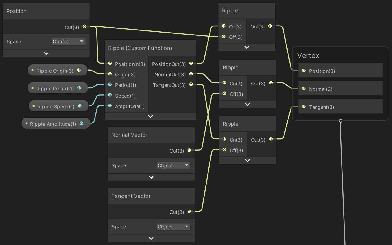
Create a custom function node for it in the graph. We only bother to include a float version, omitting the half version, so set the node's Precision to Single, which matches the float type.
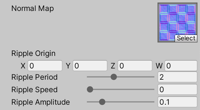
We evaluate the wave in object space, so it won't be affected by the object's transformation matrix. So feed the node the object-space position and use its output for the vertex position. Make sure that the Position node has its Space set to Object. Also add properties to the graph for the other inputs and connect them to the ripple node.
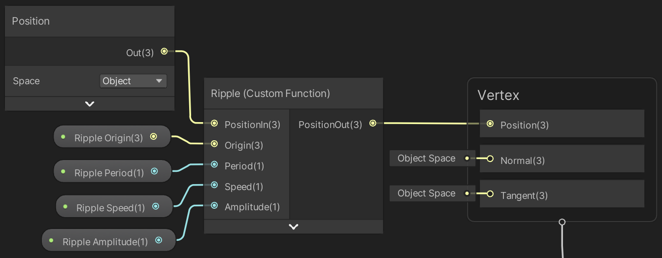
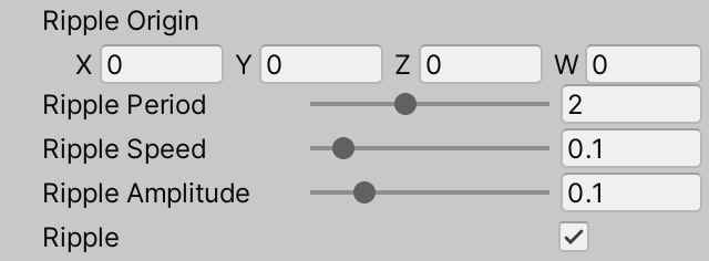
The ripple origin is a 3D vector, which makes it possible to place the origin above or below the plane. This can make the visible center of the ripple smoother. The other input parameters are all sliders, with range 0.1–5 for the period, 0–1 for speed, and 0–0.5 for amplitude.
Now add the ripple function to the output Y position in Ripple_float. To make the code easier to follow I split it into multiple sub-functions: `y=asin(f)` with `f=2pip(d-st)` and `d=||p||` where `p` is the relative 3D position, so the position minus the origin. The current time can be accessed via _Time.y.
	float3 p = PositionIn - Origin;
	float d = length(p);
	float f = 2.0 * PI * Period * (d - Speed * _Time.y);

	PositionOut = PositionIn + float3(0.0, Amplitude * sin(f), 0.0);
The higher the resolution of the grid, the smoother its surface will be and the better the ripple will look. Low resolutions will look like a mess and resolution 10 still doesn't look great. So let's increase the maximum resolution to 50 in ProceduralMesh.
	[SerializeField, Range(1, 50)]
	int resolution = 1;
Note that although the vertices now have a vertical offset the mesh bounds are still flat. This isn't a problem for our demonstration, but in general you have to be aware of possible mismatches between a mesh's bounds and its visual size due to vertex displacement. It could cause unexpected culling when the bounds fall outside the camera frustum while some of its displaces vertices would be visible.
Rippling Normals
Although the grid now ripples the shader still treats it as flat when calculating lighting, because all normal vectors still point straight up. To apply lighting correctly the ripple function also has to provide appropriate vertex normal vectors that match the ripple.
To find the normal vector we need to know the surface curvature at the vertex. We can do this by calculating the derivative of our ripple function. It is a two-dimensional function, so it has two derivatives, one per dimension, which are known as partial derivatives. In this case `y'=(2piapcos(f))/d[[x],[z]]`. Calculate them after the adjusted position.
	PositionOut = PositionIn + float3(0.0, Amplitude * sin(f), 0.0);

	float2 derivatives = (2.0 * PI * Amplitude * Period * cos(f) / d) * p.xz;
If the origin lies on the plane then `d` can become zero. To avoid a division by zero enforce a tiny minimum value for the divisor.
float2 derivatives = (2.0 * PI * Amplitude * Period * cos(f) / max(d, 0.0001)) * p.xz;
The derivates tell how much much the Y coordinate varies per unit in the X and Z dimensions. We can use that to construct a normal vector. We start with the unit X and Z vectors and add the respective derivative to their Y components. These two vectors lie on the plane that matches the surface curvature at that point. Then we take the cross product of these vectors via the cross function, which produces a vector pointing straight away from the plane in which they lie, thus giving us the normal vector that we need. To make sure that it points up rather than down we have to calculate `ZxxX` and not `XxxZ`, where `xx` represents the cross product of two vectors. Assign the result to a new normal vector output parameter.
void Ripple_float (
	float3 PositionIn, float3 Origin,
	float Period, float Speed, float Amplitude,
	out float3 PositionOut, out float3 NormalOut
) {
	…

	NormalOut = cross(float3(0.0, derivatives.y, 1.0), float3(1.0, derivatives.x, 0.0));
}
Although normal vectors should be unit-length, this isn't the case for the vector that we calculate. However, this isn't a problem because the shader normalizes it after applying the object-to-world space transformation. So add the required output to the ripple node and directly connect it to the vertex normal.
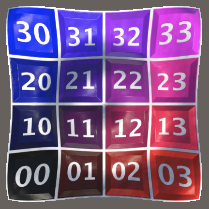
Now the grid will have correct lighting applied to it.
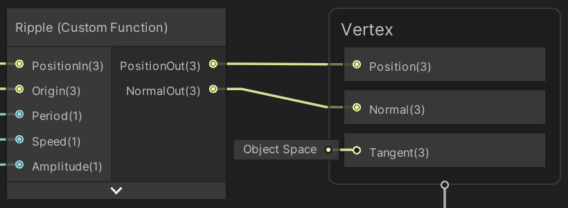
Rippling Tangents
The normal vectors are now correct, but the normal map isn't applied as correctly as could be. The tangent vectors should also match the rippling surface, but are still flat. We already calculate the required tangent vector, it's the X part of the cross product to find the normal vector. So make it available via an output parameter.
void Ripple_float (
	float3 PositionIn, float3 Origin,
	float Period, float Speed, float Amplitude,
	out float3 PositionOut, out float3 NormalOut, out float3 TangentOut
) {
	…

	TangentOut = float3(1.0, derivatives.x, 0.0);
	NormalOut = cross(float3(0.0, derivatives.y, 1.0), TangentOut);
}
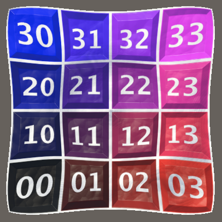
Also include it in the graph, just like we did for the vertex normal vector.
Note that the difference between correct and flat tangents isn't that obvious, which is why they're often kept flat. However, as we calculate them anyway it's free to use the correct tangent vectors.
Also note that at this point we completely replace both the normal and the tangent vectors of the mesh, so we could use a specialized IMeshStreams implementation that omits them, significantly reducing the size of the mesh. We could even go a step further and omit the texture coordinates for the shader grid, as they're always equal to the position plus 0.5. However, I won't do this and instead will stick to a mesh format that works in all cases.
Optional Ripple
We wrap up this tutorial by making the ripple effect optional. We do this by adding a boolean keyword property to the graph.
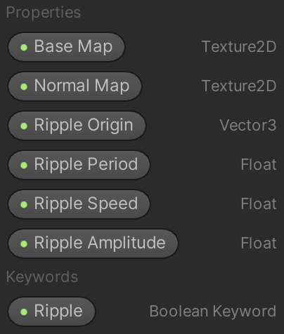
This adds a toggle option for the ripple to our material inspector.
When you drag the keyword from the blackboard onto the graph area you'll get a node that has two inputs, which allows you to provide variants for when the keyword is enabled and disabled. So when the keyword is enabled use the ripple for the position, otherwise the original position. The same goes for the normal and tangent vectors. Each has a dedicated node that provides the original mesh data. Make sure that everything is in object space.
The next tutorial is Triangle Grid.