UV Sphere
Wrapping a Grid Around a Sphere
- Visualize vertex data via gizmos.
- Wrap a square grid around a sphere.
- Eliminate degenerate triangles and unused vertices.
- Use lat/lon maps and cube maps to texture a sphere.
This is the fifth tutorial in a series about procedural meshes. This time we bend and deform a square grid to create a sphere.
This tutorial is made with Unity 2020.3.23f1.
Gizmos
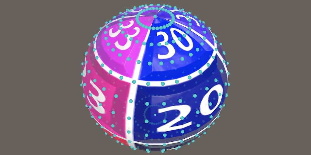
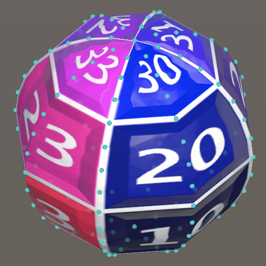
Unlike flat grids a sphere is a 3D shape. We cannot see its entire surface at once. This makes it harder to visually judge where its vertices lie. So before we start generating a sphere we'll add a way to visualize the vertex data of the mesh. We do this via Unity's Gizmos API.
Showing Vertices
To show vertices ProceduralMesh needs to access them. We do this via the simple Mesh API, retrieving them via the mesh's vertices property, which generates and returns a Vector3 array. Do this at the end of Update and keep track of the array via a field.
	Vector3[] vertices;

	…

	void Update () {
		GenerateMesh();
		enabled = false;

		vertices = mesh.vertices;
	}
To draw gizmos we need to introduce a special OnDrawGizmos method. Unity will invoke it each time it renders a new frame in the scene window. We only have vertices if a mesh has been generated in play mode, so we have to abort from the method if there isn't a mesh.
	void OnDrawGizmos () {
		if (mesh == null) {
			return;
		}
	}
We'll use small spheres to represent the vertices. We can draw a gizmo sphere by invoking Gizmos.Drawsphere with a position and a radius, for which we'll use 0.02. Do this for all vertices.
		if (mesh == null) {
			return;
		}

		for (int i = 0; i < vertices.Length; i++) {
			Gizmos.DrawSphere(vertices[i], 0.02f);
		}

The gizmos are white by default, which isn't a good color because it's hard to see on a light background. We can change the gizmo color by assigning a new one to the Gizmos.color property. Let's use cyan instead.
		Gizmos.color = Color.cyan;
		for (int i = 0; i < vertices.Length; i++) {
			Gizmos.DrawSphere(vertices[i], 0.02f);
		}

Normals and Tangents
Let's also visualize the mesh's normal and tangent vectors. These are all the same for flat grids, but it'll be more complex for spheres. The normals are 3D vectors and the tangents are 4D vectors. Retrieve and keep track of them as well, via the appropriate mesh properties.
	Vector3[] vertices, normals;

	Vector4[] tangents;

	…

	void Update () {
		GenerateMesh();
		enabled = false;

		vertices = mesh.vertices;
		normals = mesh.normals;
		tangents = mesh.tangents;
	}
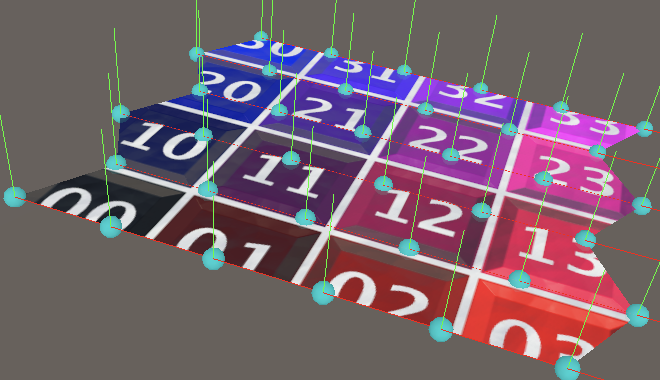
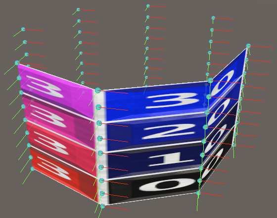
The vectors can be visualized with short lines, drawn via the Gizmos.DrawRay method. It has a starting position and a vector as parameters, for which we'll use the vertex position and the appropriate vector, scaled down to a length of 0.2. We'll make the normals green and the tangents red.
		//Gizmos.color = Color.cyan;
		for (int i = 0; i < vertices.Length; i++) {
			Vector3 position = vertices[i];
			Gizmos.color = Color.cyan;
			Gizmos.DrawSphere(position, 0.02f);
			Gizmos.color = Color.green;
			Gizmos.DrawRay(position, normals[i] * 0.2f);
			Gizmos.color = Color.red;
			Gizmos.DrawRay(position, tangents[i] * 0.2f);
		}

World-Space Gizmos
Our gizmos correctly visualize the vertex data, as long as we do not adjust the transformation of our game object. Although we use object-space data to draw the gizmos, they're drawn directly in world space, so aren't affected by the game object's transformation.
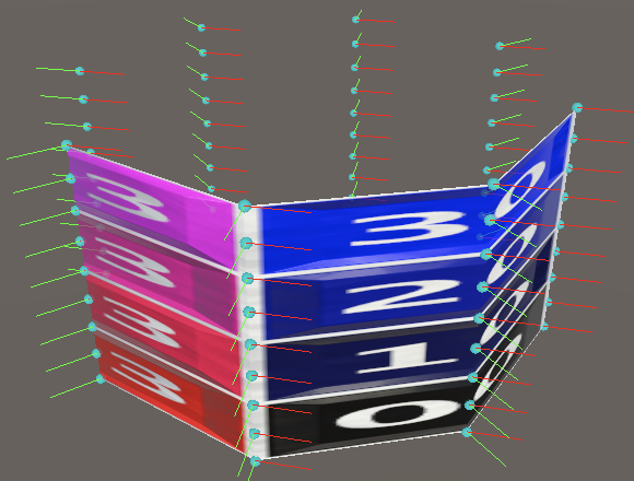
To correctly transform the vertex positions we have to invoke TransformPoint on the game object's Transform component, passing it the position. Store the component reference in a variable so we only have to access our component's transform property once.
		Transform t = transform;
		for (int i = 0; i < vertices.Length; i++) {
			Vector3 position = t.TransformPoint(vertices[i]);
			…
		}
We also have to transform the normals and tangents, which is done via the TransformDirection method. This method only applies the rotation, ignoring scale and position.
			Gizmos.DrawRay(position, t.TransformDirection(normals[i]) * 0.2f);
			Gizmos.color = Color.red;
			Gizmos.DrawRay(position, t.TransformDirection(tangents[i]) * 0.2f);
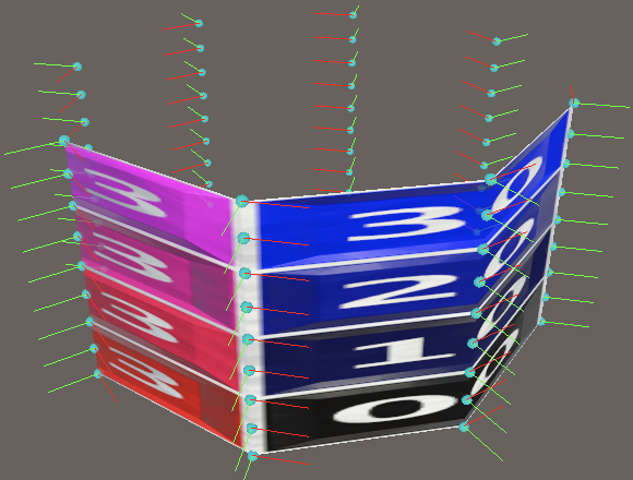
Optional Gizmos
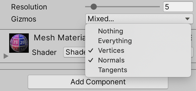
We won't be interested in seeing all vertex data all the time, so let's make what's shown configurable. Add a gizmos configuration field for this, with a new GizmoMode enum type with options for showing nothing, vertices, normals, or tangents.
	public enum GizmoMode { Nothing, Vertices, Normals, Tangents }

	[SerializeField]
	GizmoMode gizmos;
To make it possible to mix options we'll turn the enum into a set of boolean flags, where each option has its own bit. The only exception is the option for nothing, which represents none of the bits being set.
We indicate that the enum should be interpreted as boolean flags by attaching the System.Flags attribute to it. Then we use the first bit for vertices, the second for normals, and the third for tangents. So we assign explicit values to our four enum options, specifically 0, 1, binary 10, and binary 100.
	[System.Flags]
	public enum GizmoMode { Nothing = 0, Vertices = 1, Normals = 0b10, Tangents = 0b100 }
Because we might not need the mesh data anymore we'll set the array fields to null in Update.
	void Update () {
		GenerateMesh();
		enabled = false;

		vertices = null;
		normals = null;
		tangents = null;
	}
And we can also skip drawing gizmos if they're set to nothing.
	void OnDrawGizmos () {
		if (gizmos == GizmoMode.Nothing || mesh == null) {
			return;
		}

		…
	}
We can check what needs to be drawn by masking the gizmos configuration with the three visible options, using the boolean AND & operator, then checking whether the result isn't zero. Keep track of this for each option with boolean variables.
		if (gizmos == GizmoMode.Nothing || mesh == null) {
			return;
		}

		bool drawVertices = (gizmos & GizmoMode.Vertices) != 0;
		bool drawNormals = (gizmos & GizmoMode.Normals) != 0;
		bool drawTangents = (gizmos & GizmoMode.Tangents) != 0;
After what we retrieve the required mesh data. At this point vertex positions are always needed, but normals and tangents only if their visualization is enabled. Also, we only have to do this if our fields are currently set to null.
		bool drawTangents = (gizmos & GizmoMode.Tangents) != 0;

		if (vertices == null) {
			vertices = mesh.vertices;
		}
		if (drawNormals && normals == null) {
			normals = mesh.normals;
		}
		if (drawTangents && tangents == null) {
			tangents = mesh.tangents;
		}
Finally, only draw the desired gizmos in the loop.
		for (int i = 0; i < vertices.Length; i++) {
			Vector3 position = t.TransformPoint(vertices[i]);
			if (drawVertices) {
				Gizmos.color = Color.cyan;
				Gizmos.DrawSphere(position, 0.02f);
			}
			if (drawNormals) {
				Gizmos.color = Color.green;
				Gizmos.DrawRay(position, t.TransformDirection(normals[i]) * 0.2f);
			}
			if (drawTangents) {
				Gizmos.color = Color.red;
				Gizmos.DrawRay(position, t.TransformDirection(tangents[i]) * 0.2f);
			}
		}
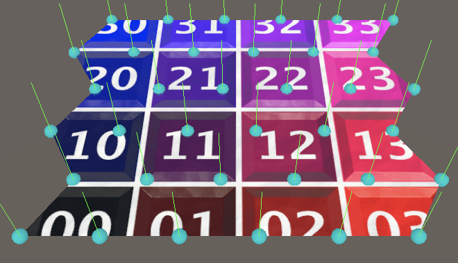
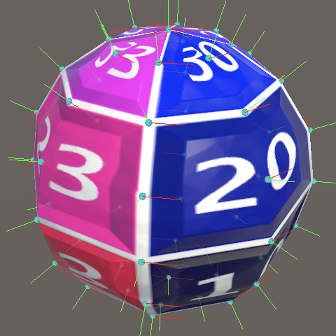
From Square to Sphere
The simplest way to create a sphere is to take a square grid, turn it into a cylinder, and then squeeze its top and bottom. The result is a spherical parametric surface commonly known as a UV sphere. We used the same approach to create a sphere in Basics / Mathematical Surfaces, although this time our UV domain is 0–1 instead of −1–1.
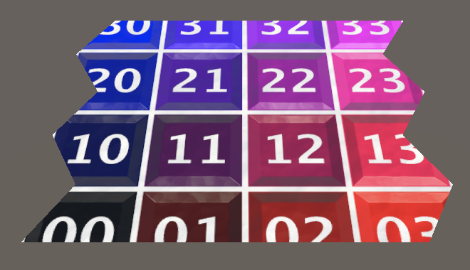
UV Square Grid
Begin by duplicating SharedSquareGrid and renaming it to UVSphere. We'll create a unit sphere, so with a radius of one. Thus its bounds should be set to 2 in all dimensions.
	public struct UVSphere : IMeshGenerator {

		public Bounds Bounds => new Bounds(Vector3.zero, new Vector3(2f, 2f, 2f));

		…
	}
Add the sphere as a mesh option to ProceduralMesh.
	static MeshJobScheduleDelegate[] jobs = {
		…
		MeshJob<PointyHexagonGrid, SingleStream>.ScheduleParallel,
		MeshJob<UVSphere, SingleStream>.ScheduleParallel
	};

	public enum MeshType {
		SquareGrid€, SharedSquareGrid€, SharedTriangleGrid€,
		FlatHexagonGrid€, PointyHexagonGrid€, UVSphere€
	};
Our current square grid lies on the XZ plane, but we'll change it to lie on the XY plane instead. Also, as we're creating a parametric surface that's not going to remain axis-aligned we'll use U and V instead of X and Z. Replace Z with U and X with V.
		public void Execute<S> (int u, S streams) where S : struct, IMeshStreams {
			int vi = (Resolution + 1) * u, ti = 2 * Resolution * (u - 1);

			…

			vertex.position.x = -0.5f;
			vertex.position.z = (float)u / Resolution - 0.5f;
			vertex.texCoord0.y = (float)u / Resolution;
			streams.SetVertex(vi, vertex);
			vi += 1;

			for (int v = 1; v <= Resolution; v++, vi++, ti += 2) {
				vertex.position.x = (float)v / Resolution - 0.5f;
				vertex.texCoord0.x = (float)v / Resolution;
				streams.SetVertex(vi, vertex);

				if (u > 0) { … }
			}
		}
This time we'll create columns from bottom to top instead of stacked rows, and we initially shift the position range from −½—½ to 0–1.
vertex.position.x = (float)u / Resolution;//vertex.position.z = (float)u / Resolution - 0.5f;vertex.texCoord0.x = (float)u / Resolution; streams.SetVertex(vi, vertex); vi += 1; for (int v = 1; v <= Resolution; v++, vi++, ti += 2) { vertex.position.y = (float)v / Resolution;// - 0.5f;vertex.texCoord0.y = (float)v / Resolution; … }
This requires us to reverse the triangle winding order, which we do by swapping the relative -1 and -Resolution - 1 vertex indices of the triangles.
					streams.SetTriangle(
						ti + 0, vi + int3€(-Resolution - 2, -Resolution - 1, -1)
					);
					streams.SetTriangle(
						ti + 1, vi + int3€(-1, -Resolution - 1, 0)
					);
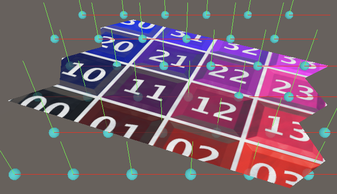
Finally, to keep the vertical grid visually correct we have to make the normal vectors point backward instead of up. The tangents remain the same, still pointing to the right.
vertex.normal.z = -1f;
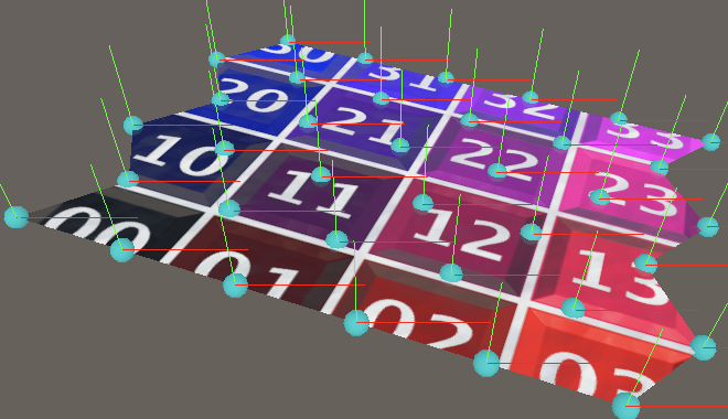
Cylinder
To turn the flat grid into a vertical cylinder we switch to using `[[sin(2piu/r)],[v/r],[-cos(2piu/r)]]` for the vertex position, with `r` being the resolution. This way the grid starts with zero for X coordinates and −1 for Z coordinates and then wraps around the origin counterclockwise.
			vertex.position.x = sin(2f * PI * u / Resolution);
			vertex.position.z = -cos(2f * PI * u / Resolution);
All vertices in a column have the same normal vector, which is equal to the position with Y fixed at zero.
//vertex.normal.z = -1f;vertex.tangent.xw = float2€(1f, -1f); vertex.position.x = sin(2f * PI * u / Resolution); vertex.position.z = -cos(2f * PI * u / Resolution); vertex.normal = vertex.position;
The tangent vectors are also constant per column. They're equal to the normal vectors, rotated 90° counterclockwise.
//vertex.tangent.xw = float2(1f, -1f);vertex.tangent.w = -1f; vertex.position.x = sin(2f * PI * u / Resolution); vertex.position.z = -cos(2f * PI * u / Resolution); vertex.normal = vertex.position; vertex.tangent.x = -vertex.position.z; vertex.tangent.z = vertex.position.x;
Sphere
To go from cylinder to sphere we have to squeeze it at the top and bottom, creating the north and south poles. Thus our horizontal vertex rings no longer all have the same radius, except for the poles, where the radius is zero. We start with the south pole, so the position and normal vectors both point down.
var vertex = new Vertex(); vertex.position.y = vertex.normal.y = -1f; vertex.tangent.w = -1f;//vertex.position.x = sin(2f * PI * u / Resolution);//vertex.position.z = -cos(2f * PI * u / Resolution);//vertex.normal = vertex.position;
However, we can still use the constant circle point as a basis for all vertices in the column, by adjusting its radius later. And the tangents are still constant per column, as they aren't affected by the radius. So let's calculate the same again, now storing the 2D circle coordinates in a separate variable. We can also delay negating the cosine until after setting the tangent.
//vertex.tangent.x = -vertex.position.z;//vertex.tangent.z = vertex.position.x;float2 circle; circle.x = sin(2f * PI * u / Resolution); circle.y = cos(2f * PI * u / Resolution); vertex.tangent.xz = circle.yx; circle.y = -circle.y;
The circle radius is equal to `sin(piv/r)` from pole to pole.
			for (int v = 1; v <= Resolution; v++, vi++, ti += 2) {
				float circleRadius = sin(PI * v / Resolution);
				vertex.position.xz = circle * circleRadius;
				vertex.position.y = (float)v / Resolution;
				…
			}
And we also have to set the Y coordinates to `-cos(piv/r)` to make it spherical.
vertex.position.y = -cos(PI * v / Resolution);
With the position correct we can once again use it for the normal vector as well.
				vertex.position.y = -cos(PI * v / Resolution);
				vertex.normal = vertex.position;
Sphere Resolution
Because our sphere isn't a flat grid it degenerates when the resolution is too low. Let's first consider vertex columns. Each column represents half a meridian on our sphere, a half-circle line going from pole to pole, with fixed longitude and varying latitude. At resolution 1 we only have two vertices along this line, at the poles. Thus our sphere mesh is reduced to an invisible line. We need at least resolution 2, which would add a vertex on the equator. This gives us a single quad per quadrant, one of the south hemisphere and one on the north hemisphere.
We could enforce a minimum resolution of 2, but let's instead change how we apply the resolution to our UV sphere. Instead of applying the resolution to the entire south-north line, we apply it per quadrant. Thus we effectively double the resolution in the V dimension of our parametric surface. To make it easy to work with this adjusted resolution introduce a private ResolutionV property for it.
int ResolutionV => 2 * Resolution;
Use this new resolution instead of the regular one for the V dimension when determining the vertex and index counts.
		public int VertexCount => (Resolution + 1) * (ResolutionV + 1);

		public int IndexCount => 6 * Resolution * ResolutionV;
We also need to use it when determining the offsets of the vertex and triangle indices at the start of Execute.
int vi = (ResolutionV + 1) * u, ti = 2 * ResolutionV * (u - 1);
And the entire loop also need to use it.
			for (int v = 1; v <= ResolutionV; v++, vi++, ti += 2) {
				float circleRadius = sin(PI * v / ResolutionV);
				vertex.position.xz = circle * circleRadius;
				vertex.position.y = -cos(PI * v / ResolutionV);
				vertex.normal = vertex.position;
				vertex.texCoord0.y = (float)v / ResolutionV;

				if (u > 0) {
					streams.SetTriangle(
						ti + 0, vi + int3(-ResolutionV - 2, -ResolutionV - 1, -1)
					);
					streams.SetTriangle(
						ti + 1, vi + int3(-1, -ResolutionV - 1, 0)
					);
				}
			}
We have to do the same for the resolution in the U dimension. As in this case we're dealing with entire circles of latitude—and thus four quadrants—it makes most sense to use quadruple the original resolution. Add a property for this as well.
int ResolutionU => 4 * Resolution;
Use the U resolution for the vertex and index counts, and also for the job length.
		public int VertexCount => (ResolutionU + 1) * (ResolutionV + 1);

		public int IndexCount => 6 * ResolutionU * ResolutionV;

		public int JobLength => ResolutionU + 1;
In Execute the U resolution is used to construct the circle and horizontal texture coordinates, before the loop.
			circle.x = sin(2f * PI * u / ResolutionU);
			circle.y = cos(2f * PI * u / ResolutionU);
			vertex.tangent.xz = circle.yx;
			circle.y = -circle.y;
			vertex.texCoord0.x = (float)u / ResolutionU;
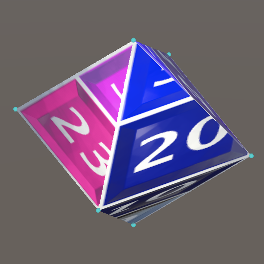
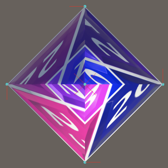
Now our sphere is reduced to a tetrahedron at resolution 1, which doesn't look much like a sphere but is at least a valid 3D shape. The vertex distribution now roughly approximates a square lattice near the equator. The vertices do bunch up at the poles, but this is inherent to the parametric surface and we cannot avoid it.
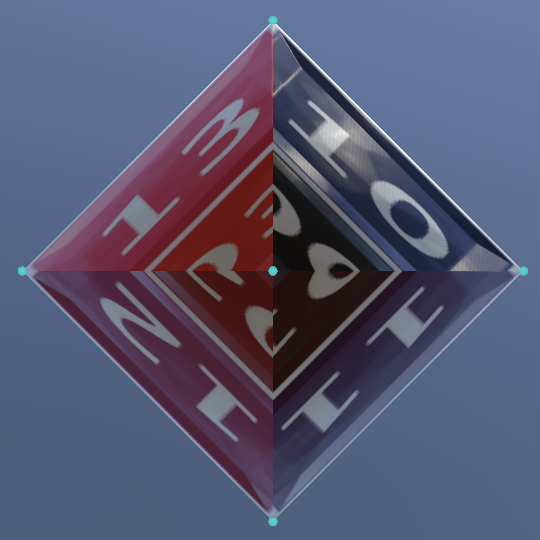
South Pole
When investigating the poles of our sphere it becomes clear that the quads that touch them degenerate into triangles, because the circles of latitude at the poles have a radius of zero. This is most obvious at resolution 1, with all quads are affected. Let's analyze the south pole of this octahedron-like sphere.
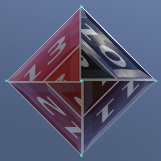
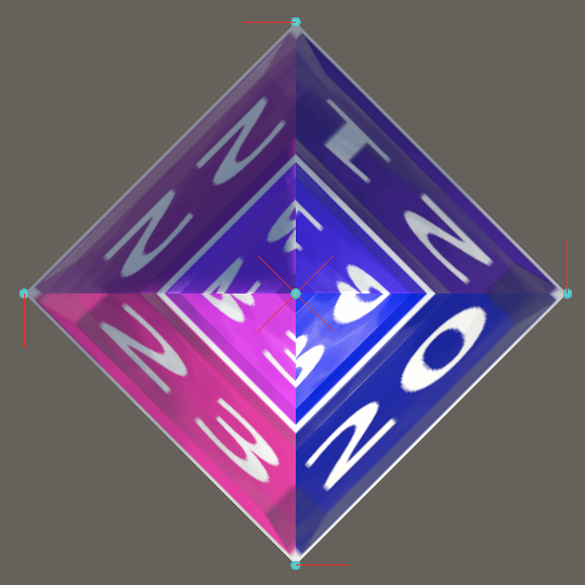
Besides a missing triangle per quad it is also obvious that the texture is twisted. This happens because we only see the triangle that uses the vertex from the same meridian generated when setting the triangle column. This vertex has the same horizontal coordinate as the rest of the line, but visually it can be considered to lie in between both meridians of a triangle column. So it makes more sense to shift the texture coordinate counterclockwise by half a step for the first vertex.
			vertex.texCoord0.x = (u - 0.5f) / ResolutionU;
			streams.SetVertex(vi, vertex);
			vi += 1;
			vertex.texCoord0.x = (float)u / ResolutionU;
This straightens the texture horizontally. There is still a discontinuity between adjacent triangles, skipping a triangular region, but we cannot get rid of these seams.
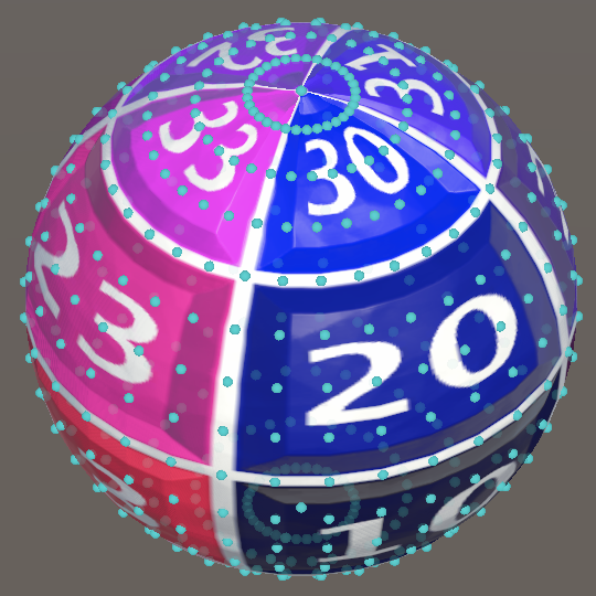
There is a similar problem with the tangents. When their gizmos are turned on it is clear that they also match those of the meridians.
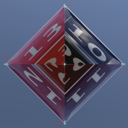
But once again it makes more sense to set the bottom vertex tangent to halfway between the meridians, going counterclockwise by half a step. Let's also move all code for the first vertex above the circle.
var vertex = new Vertex(); vertex.position.y = vertex.normal.y = -1f; vertex.tangent.x = cos(2f * PI * (u - 0.5f) / ResolutionU); vertex.tangent.z = sin(2f * PI * (u - 0.5f) / ResolutionU); vertex.tangent.w = -1f; vertex.texCoord0.x = (u - 0.5f) / ResolutionU; streams.SetVertex(vi, vertex); vi += 1; float2 circle; circle.x = sin(2f * PI * u / ResolutionU); circle.y = cos(2f * PI * u / ResolutionU); vertex.tangent.xz = circle.yx; circle.y = -circle.y;//vertex.texCoord0.x = (u - 0.5f) / ResolutionU;//streams.SetVertex(vi, vertex);//vi += 1;vertex.texCoord0.x = (float)u / ResolutionU;
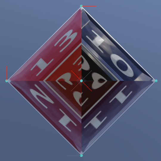
Although the visual difference is slight, this fixes the twisting of tangent space.
North Pole
The north pole has the same problem that the south pole had, so we have to fix it as well.
Because both polar vertices have the same tangents and horizontal texture coordinates we can set the north pole vertex directly after setting the south pole vertex, before the loop. We only have to set its Y position and normal components and its vertical texture coordinate to 1.
			streams.SetVertex(vi, vertex);

			vertex.position.y = vertex.normal.y = 1f;
			vertex.texCoord0.y = 1f;
			streams.SetVertex(vi + ResolutionV, vertex);
			vi += 1;
To prevent the loop from setting the north pole vertex we have to shorten it by one iteration. So instead of continuing while V is less that or equal to the V resolution it must be strictly less than the V resolution. To keep setting the last quad we now need to duplicate the triangle-setting block from the loop and insert it after the loop.
			for (int v = 1; v < ResolutionV; v++, vi++, ti += 2) { … }

			if (u > 0) {
				streams.SetTriangle(
					ti + 0, vi + int3€(-ResolutionV - 2, -ResolutionV - 1, -1)
				);
				streams.SetTriangle(
					ti + 1, vi + int3€(-1, -ResolutionV - 1, 0)
				);
			}
We initially get a result that is even more twisted than before, because we only see the first triangle of the quad and it uses the vertex from the previous meridian. We have to change it so we use the one from the current meridian.
				streams.SetTriangle(
					ti + 0, vi + int3€(-ResolutionV - 2, 0, -1)
				);
Degenerate Triangles
Because the quads that touch the poles degenerate into triangles each of those quads has one triangle that isn't visible. At the north pole this is the second triangle. We can demonstrate that it isn't needed by collapsing it to a single point, by only using the first vertex index. This doesn't affect the appearance of the sphere.
				streams.SetTriangle(
					ti + 0, vi + int3€(-ResolutionV - 2, 0, -1)
				);
				streams.SetTriangle(
					ti + 1, 0
				);
We can do the same at the south pole, though in this case it's the first triangle of the quad. To make this work we have to also insert the triangle-setting block before the loop and make the loop skip setting triangles during its first iteration. Also put the statement that increments the triangle index inside these block instead of in the for statement.
			if (u > 0) {
				streams.SetTriangle(
					ti + 0, 0
				);
				streams.SetTriangle(
					ti + 1, vi + int3€(-1, -ResolutionV - 1, 0)
				);
				ti += 2;
			}

			for (int v = 1; v < ResolutionV; v++, vi++) { //, ti += 2) {
				…

				if (u > 0 && v > 1) {
					streams.SetTriangle(
						ti + 0, vi + int3€(-ResolutionV - 2, -ResolutionV - 1, -1)
					);
					streams.SetTriangle(
						ti + 1, vi + int3€(-1, -ResolutionV - 1, 0)
					);
					ti += 2;
				}
			}
The sphere still appears the same. Now we can eliminate the degenerate triangles from the mesh. There are two per column, so there is effectively one less quad per column. Adjust the index count accordingly.
public int IndexCount => 6 * ResolutionU * (ResolutionV - 1);
Also adjust the triangle offset at the start of Execute.
int vi = (ResolutionV + 1) * u, ti = 2 * (ResolutionV - 1) * (u - 1);
Then remove the code that adds the degenerate triangles. Make sure that the triangle index is incremented only once before the loop starts.
			if (u > 0) {
				//streams.SetTriangle(ti + 0, 0);
				streams.SetTriangle(ti, vi + int3€(-1, -ResolutionV - 1, 0));
				ti += 1;
			}

			for (int v = 1; v < ResolutionV; v++, vi++) { … }

			if (u > 0) {
				streams.SetTriangle(ti, vi + int3€(-ResolutionV - 2, 0, -1));
				//streams.SetTriangle(ti + 1, 0);
			}
Vertex Seam
Our code has become a bit messy with all the checks based on U and V. We can simplify things by considering the first vertex line a special case. This is the line that doesn't have its own accompanying triangle column and it overlaps the last vertex line. Let's consider this the vertex seam that stitches both sides of the wrapped grid together.
Duplicate Execute and rename it to ExecuteSeam. We'll use this method for the single case when U equals zero, so remove its U parameter and replace all usage of U with constant values. Also eliminate all code that deals with triangles.
		public void ExecuteSeam<S> (S streams) where S : struct, IMeshStreams {
			int vi = 0; //, ti = …

			var vertex = new Vertex();
			vertex.position.y = vertex.normal.y = -1f;
			vertex.tangent.x = cos(2f * PI * 0.5f / ResolutionU);
			vertex.tangent.z = sin(2f * PI * 0.5f / ResolutionU);
			vertex.tangent.w = -1f;
			vertex.texCoord0.x = 0.5f / ResolutionU;
			streams.SetVertex(vi, vertex);

			…

			float2 circle;
			circle.x = sin(0f);
			circle.y = cos(0f);
			vertex.tangent.xz = circle.yx;
			circle.y = -circle.y;
			vertex.texCoord0.x = 0f;

			//if (u > 0) { … }

			for (int v = 1; v < ResolutionV; v++, vi++) {
				…

				//if (u > 0 && v > 1) { … }
			}

			//if (u > 0) { … }
		}
Next, rename Execute to ExecuteRegular and remove the code that checks whether U is greater than zero, because that will always be the case.
		public void ExecuteRegular<S> (int u, S streams) where S : struct, IMeshStreams {
			…

			//if (u > 0) {
			streams.SetTriangle(ti, vi + int3(-1, -ResolutionV - 1, 0));
			ti += 1;
			//}

			for (int v = 1; v < ResolutionV; v++, vi++) {
				…

				if (v > 1) { … }
			}

			//if (u > 0) {
			streams.SetTriangle(ti, vi + int3(-ResolutionV - 2, 0, -1));
			//}
		}
Now introduce a new Execute method that invokes ExecuteSeam when U equals zero and invokes ExecuteRegular otherwise.
		public void Execute<S> (int u, S streams) where S : struct, IMeshStreams {
			if (u == 0) {
				ExecuteSeam(streams);
			}
			else {
				ExecuteRegular(u, streams);
			}
		}
At this point our sphere still gets generated correctly, but we can simplify ExecuteSeam further. We don't need to calculate the circle point because the sine of zero is zero and the cosine of zero is one.
//float2 circle;//circle.x = sin(0f);//circle.y = cos(0f);vertex.tangent.xz = float2€(1f, 0f);//circle.y = -circle.y;vertex.texCoord0.x = 0f; for (int v = 1; v < ResolutionV; v++, vi++) { float circleRadius = sin(PI * v / ResolutionV);//vertex.position.xz = circle * circleRadius;vertex.position.z = -circleRadius; … }
Also, because all regular columns use their own polar vertices the seam doesn't need polar vertices of its own. Thus we can reduce the vertex count by two.
public int VertexCount => (ResolutionU + 1) * (ResolutionV + 1) - 2;
This simplifies ExecuteSeam further, eliminating the polar vertices. We can now also directly use the iterator variable of the loop—minus one—instead of having to rely on a separate vertex index.
//int vi = 0;var vertex = new Vertex();//vertex.position.y = vertex.normal.y = -1f;vertex.tangent.x = 1f;//vertex.tangent.z = sin(2f * PI * 0.5f / ResolutionU);vertex.tangent.w = -1f;//vertex.texCoord0.x = 0.5f / ResolutionU;//streams.SetVertex(vi, vertex);//…for (int v = 1; v < ResolutionV; v++) { //, vi++) { … streams.SetVertex(v - 1, vertex); }
To make this work we also have to adjust ExecuteRegular at bit. First, the initial vertex index is reduced by two.
int vi = (ResolutionV + 1) * u - 2, ti = 2 * (ResolutionV - 1) * (u - 1);
Second, the vertex offset to the vertex line on the left side of the triangle column is now different for the first triangle column, when U equals 1. This is the case because the seam doesn't have a north pole vertex. To make this easy to code we'll put the vertex offset that shifts to the left vertex line in a variable. This shift to the left would get us the top left vertex index of the quad.
			int shiftLeft = -ResolutionV - 1;

			streams.SetTriangle(ti, vi + int3€(-1, shiftLeft, 0));
			ti += 1;

			for (int v = 1; v < ResolutionV; v++, vi++) {
				…

				if (v > 1) {
					streams.SetTriangle(ti + 0, vi + int3€(shiftLeft - 1, shiftLeft, -1));
					streams.SetTriangle(ti + 1, vi + int3€(-1, shiftLeft, 0));
					ti += 2;
				}
			}

			streams.SetTriangle(ti, vi + int3€(shiftLeft - 1, 0, -1));
Instead of writing -Resolution - 1 we can also write -1 - Resolution.
int shiftLeft = -1 - ResolutionV;
When we're dealing with the seam that misses the north pole vertex we must compensate for that gap, by starting at 0 instead of −1.
int shiftLeft = (u == 1 ? 0 : -1) - ResolutionV;
At this point our sphere is still the same, but now without two useless vertices.
Sincos
There is one more easy optimization that we can make. When inspecting the code generated by Burst we find multiple call instructions to burst.Sleef_sinf_u35 and burst.Sleef_cosf_u35, matching our calculations of sines and cosines. These are jumps to code blocks that calculate the trigonometric functions. Ideally we minimize the amount of call instructions to keep execution local and also try to keep the amount of trigonometry to a minimum. We can do both by taking advantage of the sincos method from the Mathematics API.
The sincos method calculates the sine and cosine for the same value together, which can save some work compared to calculating them separately. It has three parameters. Its first parameter is the input value. Its other two parameters are outputs for the calculated sine and cosine values.
Beginning with the calculation of the polar tangent in ExecuteRegular, we can directly supply the tangent components as output arguments, by writing out in front of each.
var vertex = new Vertex(); vertex.position.y = vertex.normal.y = -1f;//vertex.tangent.x = cos(2f * PI * (u - 0.5f) / ResolutionU);//vertex.tangent.z = sin(2f * PI * (u - 0.5f) / ResolutionU);sincos( 2f * PI * (u - 0.5f) / ResolutionU, out vertex.tangent.z, out vertex.tangent.x );
We can do the same when calculating the circle.
float2 circle;//circle.x = sin(2f * PI * u / ResolutionU);//circle.y = cos(2f * PI * u / ResolutionU);sincos(2f * PI * u / ResolutionU, out circle.x, out circle.y);
And when calculating the circle radius and Y position inside the loop.
			for (int v = 1; v < ResolutionV; v++, vi++) {
				sincos(
					PI * v / ResolutionV,
					out float circleRadius, out vertex.position.y
				);
				//float circleRadius = sin(PI * v / ResolutionV);
				vertex.position.xz = circle * circleRadius;
				vertex.position.y = -vertex.position.y;
				…
			}
In this case we can also eliminate the statement that negates the Y position by rotating 180° via the addition of π to the sincos input. This means that we now have to negate the radius instead, but we don't need an extra line of code for that.
sincos( PI + PI * v / ResolutionV, out float circleRadius, out vertex.position.y ); vertex.position.xz = circle * -circleRadius;//vertex.position.y = -vertex.position.y;
Apply the same trick to the loop inside ExecuteSeam. In this case we end up not needing any negations at all.
			for (int v = 1; v < ResolutionV; v++) {
				sincos(
					PI + PI * v / ResolutionV,
					out vertex.position.z, out vertex.position.y
				);
				//float circleRadius = sin(PI * v / ResolutionV);
				//vertex.position.z = -circleRadius;
				//vertex.position.y = -cos(PI * v / ResolutionV);
				…
			}
Inspecting the code generated by Burst now reveals that the call instructions are gone. Burst has inserted the sincos code directly into our job.
Texturing a Sphere
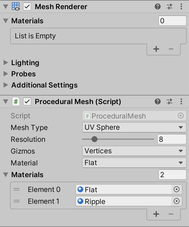
The material that we currently use isn't appropriate for projection onto a sphere, especially when it is set to ripple. So we'll provide alternative materials for when showing a sphere.
Material Selection
To make switching materials easier we'll add a material configuration option to ProceduralMesh, using a new MaterialMode enum type. Initially provide options for a flat and a ripple material.
	public enum MaterialMode { Flat, Ripple }

	[SerializeField]
	MaterialMode material;
To make this work we also need a reference to these materials. Add a material array configuration option for this as well.
	[SerializeField]
	Material[] materials;
Then we can select the appropriate material and assign it to the material property of the MeshRenderer component in Update.
	void Update () {
		…

		GetComponent<MeshRenderer>().material = materials[(int)material];
	}
Duplicate our current material so we get two variants, one with the ripple disabled, named Flat and one with the ripple enabled, named Ripple. Add these to the Materials array of our component, in the appropriate order. Then also remove the material from the MeshRenderer component's array, as we now set it ourselves.
Lat/Lon Maps
Our sphere's texture coordinates match the equirectangular projection of a sphere onto a rectangle. It projects the meridians and circles of latitude onto straight lines, partitioning the map into regular squares. Textures with this projection are commonly known as lat/lon maps. They typically have a 2:1 aspect ratio. Here is a base map that uses such a projection.
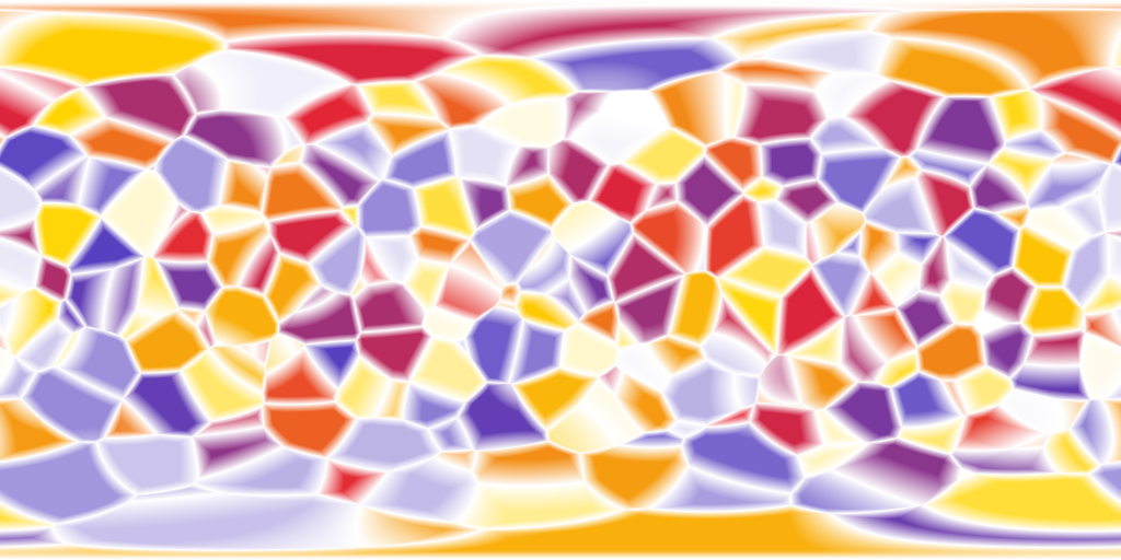
And Here is an accompanying normal map.
Add an entry for the lat/lon map to MaterialMode.
public enum MaterialMode { Flat, Ripple, LatLonMap }
Then duplicate the Flat material, rename it appropriately, and use the lat/lon textures for it.
This kind of map fits the sphere much better, not showing any obvious distortion near the poles. However, it doesn't hide the discontinuities of the texture coordinates in the mesh itself. The texture could be designed to take these discontinuities into account, hiding them, but only for a specific fixed sphere resolution. If you're concerned about the quality of the poles then there are better options.
Cube Maps
An alternative way to texture a sphere is by using cube maps. The benefit of a cube map over a lat/lon map is that it has a much more uniform mapping. Better texture quality can be achieved with smaller textures.
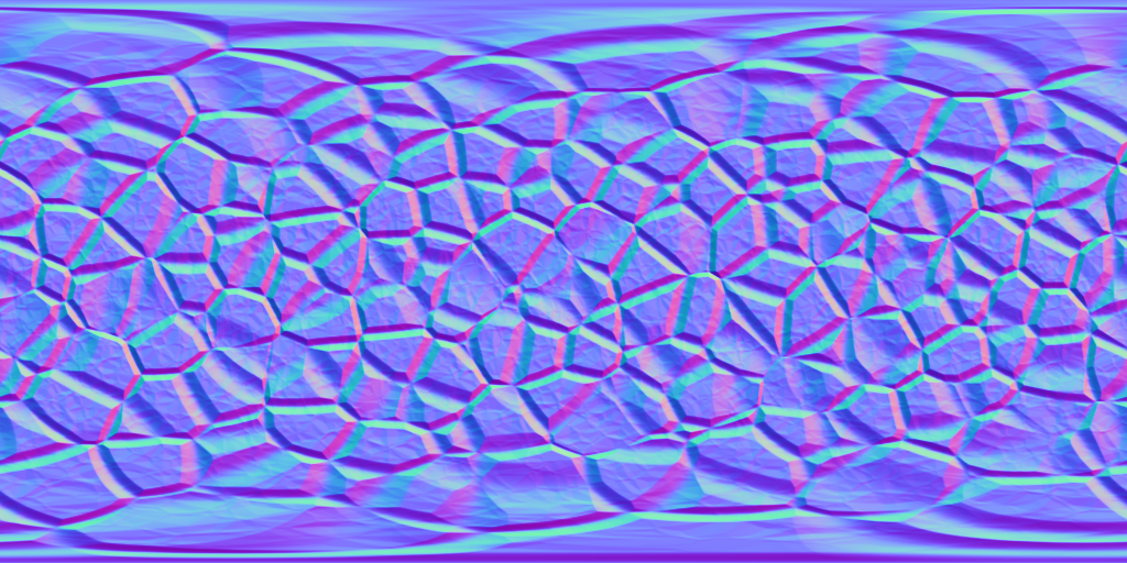
Here is a cube base map, using a horizontal layout that places the six cube faces in a row.

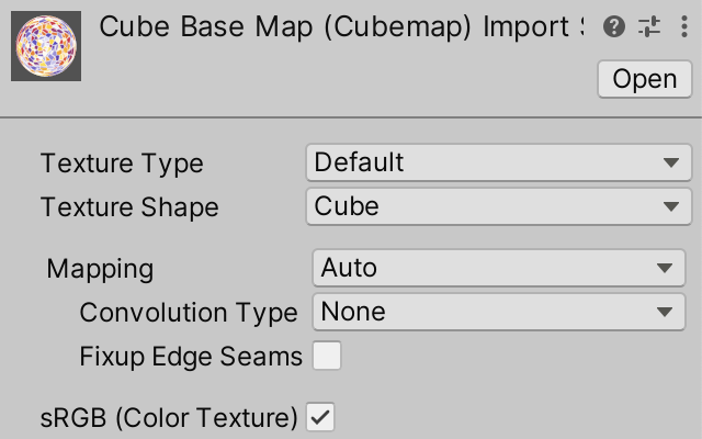
After importing it into Unity set its Texture Shape to Cube. All other options can remain at their default values. Unity will automatically detect the row layout and convert the texture to a valid cube map.
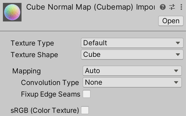
And here is an accompanying normal cube map, using the same layout.

This normal maps doesn't look like a common normal map because it stores the normal vectors in object space instead of in tangent space. Thus its vectors point in all directions instead of mostly up.
When importing this normal map its Texture Type should be kept as Default and not set to Normal map, because otherwise Unity would interpret it as a tangent-space normal map and perform an incorrect conversion. We do have to explicitly turn off sRGB (Color Texture) to indicate that this texture does not contain color data and sRGB color conversion should not be applied when sampling it.
Cube Map Shader Graph
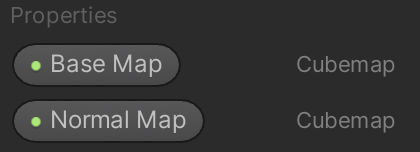
Create a new shader graph for a material based on cube maps. Give it Base Map and Normal Map properties, both of the Cubemap type.
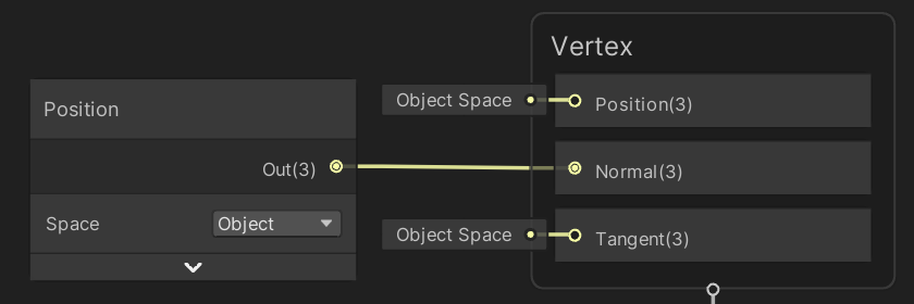
To use the base map for the base color we can pass it to a Sample Cubemap node. Instead of regular texture coordinates we need to pass it a direction vector, for which we can use the object-space position. The node indicates that it needs a world-space vector because Unity again assumes we're sampling an environment map.
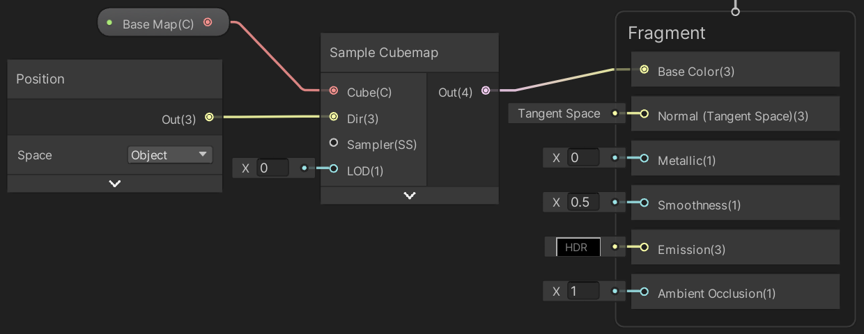
Although this is enough to use the cube map for the base color, this won't produce satisfying results. Because the Sample Cubemap node is assumed to be used for sampling environmental reflections it has a LOD parameter that's used to manually select a mipmap of the texture. This is used to control the sharpness of the reflections. However, we don't need manual control here, we want to automatically get the correct mipmap, as if sampling a regular texture. The solution is to use a CustomCubemap custom function node instead.
Give the custom function node a Cube cube map input and a Dir 3D vector input. Give in a single Out 3D vector output.
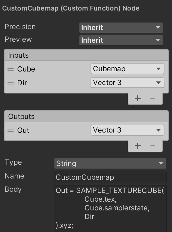
The code body of the node consists of invoking the SAMPLE_TEXTURECUBE macro, with the tex and samplerstate fields of Cube as argument, followed by the sample direction. We only need the first three components of the result.
Out = SAMPLE_TEXTURECUBE(
	Cube.tex,
	Cube.samplerstate,
	Dir
).xyz;
Now use our custom node instead of Sample Cubemap.
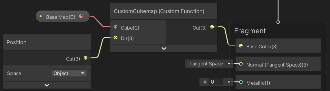
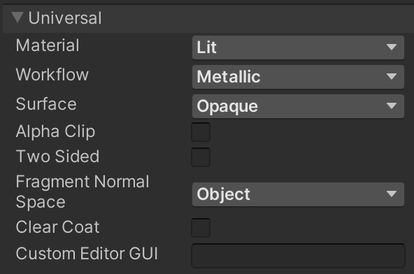
To apply our object-space normal map we have to first set the graph's Fragment Normal Space to Object.
Then use a duplicate of our custom function node to sample the normal map, convert the vector range from 0–1 to −1–1, and use it to set the object-space fragment normal.
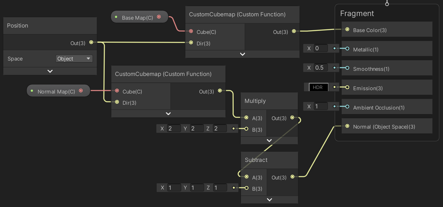
Finally, create a material from this shader graph, add it to our game object's materials array, and add an entry for it to MaterialMode.
public enum MaterialMode { Flat, Ripple, LatLonMap, CubeMap }
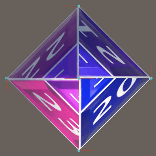
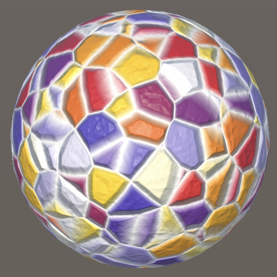
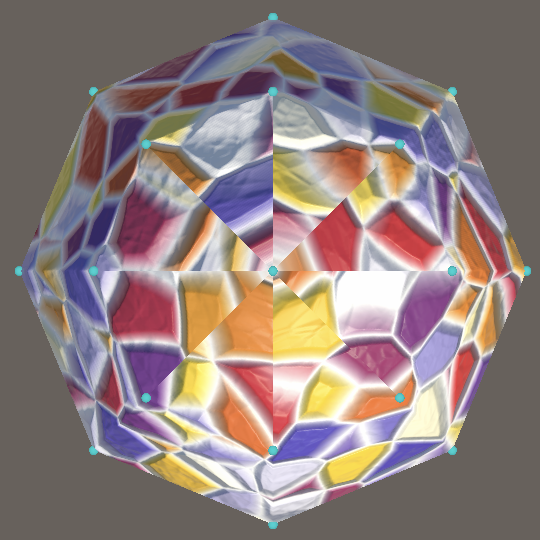
Along the equator of our sphere the cube map and the lat/lon map look mostly the same, but the quality of the cube map is superior the closer you get to the poles. There are no discontinuities at the poles, because the cube map does not rely on the texture coordinates of the mesh.
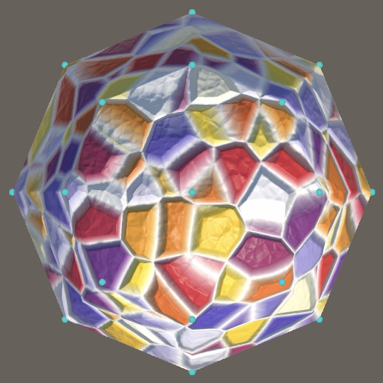
This also means that only vertex positions are needed when relying on cube maps. Texture coordinates, normal vectors, and tangent vectors can be omitted. If the original vertex normals are needed—for example for shadow sampling offsets—the object-space vertex positions can be used instead. Note that you need to use separate object-space position nodes for supplying vertex and fragment data in shader graph.
The next tutorial is Cube Sphere.