Rendering 6
Bumpiness
- Perturb normals to simulate bumps.
- Compute normals from a height field.
- Sample and blend normal maps.
- Convert from tangent space to world space.
This is the sixth part of a tutorial series about rendering. The previous part added support for more complex lighting. This time, we'll create the illusion of more complex surfaces.
This tutorial was made with Unity 5.4.0f3.
Bump Mapping
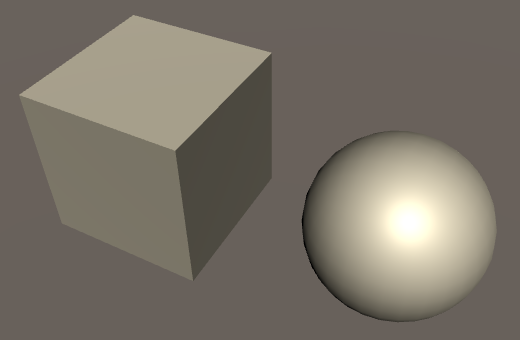
We can use albedo textures to create materials with complex color patterns. We can use normals to adjust the apparent surface curvature. With these tools, we can produces all kinds of surfaces. However, the surface of a single triangle will always be smooth. It can only interpolate between three normal vectors. So it cannot represent a rough or varied surface. This becomes obvious when forsaking an albedo texture and using only a solid color.
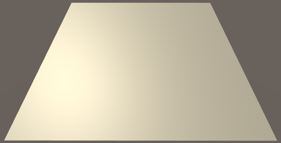
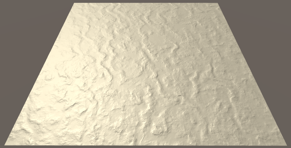
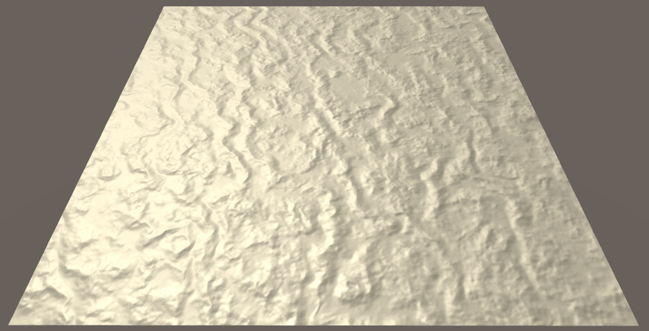
A good example of this flatness is a simple quad. Add one to the scene and make it point upwards, by rotating it 90° around the X axis. Give it our Lighting material, without textures and with a fully white tint.

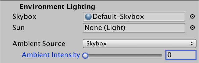
Because the default skybox is very bright, it is hard to see the contribution of the other lights. So let's turn it off for this tutorial. You can do so by decreasing the Ambient Intensity to zero in the lighting settings. Then only enable the main directional light. Find a good point of view in the scene view so you can some light differences on the quad.
How could we make this quad appear non-flat? We could fake roughness by baking shading into the albedo texture. However, that would be completely static. If the lights change, or the objects move, so should the shading. If it doesn't, the illusion will be broken. And in case of specular reflections, even the camera isn't allowed to move.
We can change the normals to create the illusion of a curving surface. But there are only four normals per quad, one for each vertex. This can only produce smooth transitions. If we want a varied and rough surface, we need more normals.
We could subdivide our quad into smaller quads. This gives us more normals to work with. In fact, once we have more vertices, we can also move them around. Then we don't need the illusion of roughness, we can make an actual rough surface! But the sub-quads still have the same problem. Are we going to subdivide those too? That will lead to huge meshes with an enormous amount of triangles. That is fine when creating 3D models, but isn't feasible for real-time use in games.
Height Maps
A rough surface has a non-uniform elevation, compared to a flat surface. If we store this elevation data in a texture, we might be able to use it generate normal vectors per fragment, instead of per vertex. This idea is known as bump mapping, and was first formulated by James Blinn.
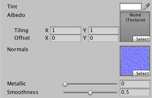
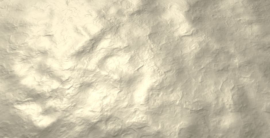
Here is a height map to accompany our marble texture. It is an RGB texture with each channel set to the same value. Import it into your project, with the default import settings.
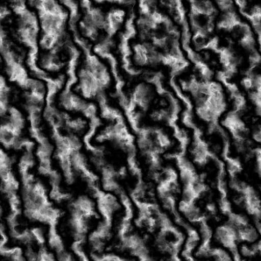
Add a _HeightMap texture property to My First Lighting Shader. As it'll use the same UV as our albedo texture, it doesn't need its own scale and offset parameters. The default texture doesn't really matter, as long as it's uniform. Gray will do.
	Properties {
		_Tint ("Tint", Color) = (1, 1, 1, 1)
		_MainTex ("Albedo", 2D) = "white" {}
		[NoScaleOffset] _HeightMap ("Heights", 2D) = "gray" {}
		[Gamma] _Metallic ("Metallic", Range(0, 1)) = 0
		_Smoothness ("Smoothness", Range(0, 1)) = 0.1
	}
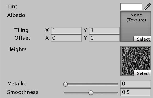
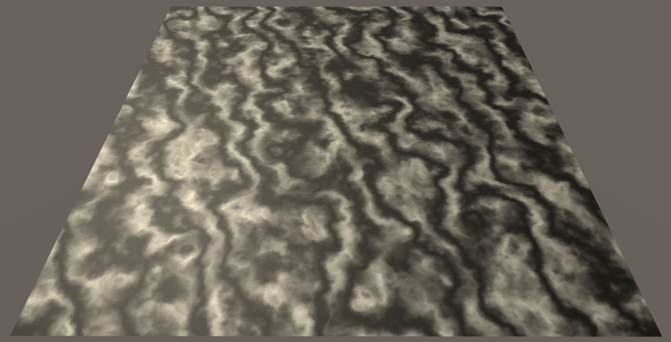
Add the matching variable to the My Lighting include file, so we can access the texture. Let's see how it looks, by factoring it into the albedo.
float4 _Tint;
sampler2D _MainTex;
float4 _MainTex_ST;

sampler2D _HeightMap;

…

float4 MyFragmentProgram (Interpolators i) : SV_TARGET {
	i.normal = normalize(i.normal);

	float3 viewDir = normalize(_WorldSpaceCameraPos - i.worldPos);

	float3 albedo = tex2D(_MainTex, i.uv).rgb * _Tint.rgb;
	albedo *= tex2D(_HeightMap, i.uv);

	…
}
Adjusting Normals
Because our fragment normals are going to become more complex, let's move their initialization to a separate function. Also, get rid the height map test code.
void InitializeFragmentNormal(inout Interpolators i) {
	i.normal = normalize(i.normal);
}

float4 MyFragmentProgram (Interpolators i) : SV_TARGET {
	InitializeFragmentNormal(i);

	float3 viewDir = normalize(_WorldSpaceCameraPos - i.worldPos);

	float3 albedo = tex2D(_MainTex, i.uv).rgb * _Tint.rgb;
//	albedo *= tex2D(_HeightMap, i.uv);

	…
}
Because we're currently working with a quad that lies in the XZ plane, its normal vector is always (0, 1, 0). So we can use a constant normal, ignoring the vertex data. Let's do that for now, and worry about different orientations later.
void InitializeFragmentNormal(inout Interpolators i) {
	i.normal = float3(0, 1, 0);
	i.normal = normalize(i.normal);
}
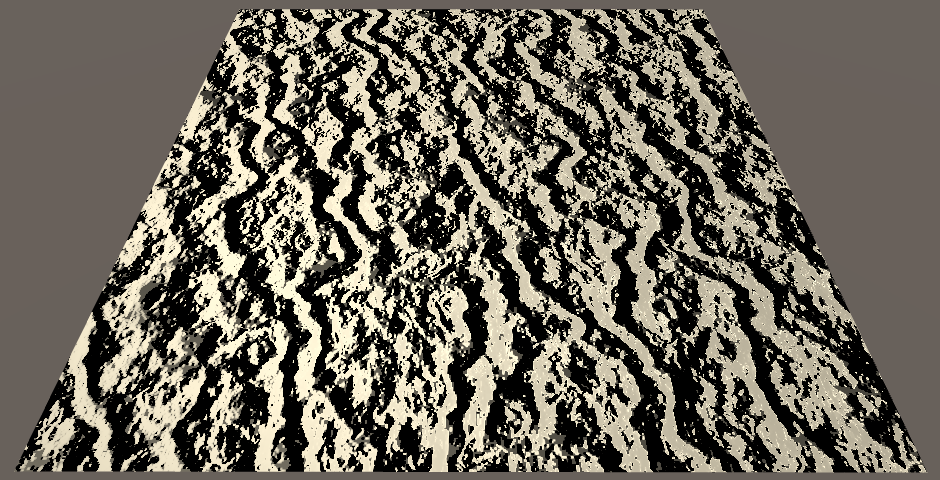
How do we include the height data in this? A naive approach is to use the height as the normal's Y component, before normalizing.
void InitializeFragmentNormal(inout Interpolators i) {
	float h = tex2D(_HeightMap, i.uv);
	i.normal = float3(0, h, 0);
	i.normal = normalize(i.normal);
}
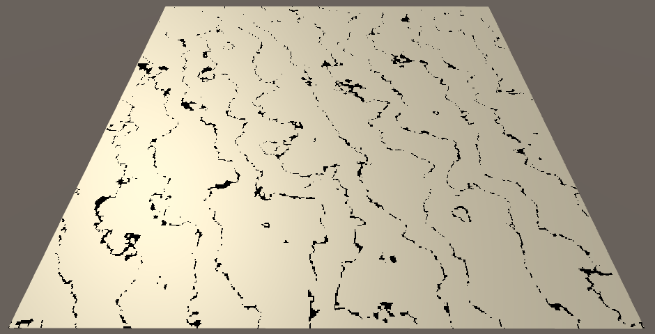
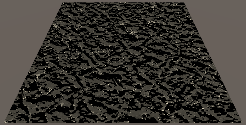
This doesn't work, because normalization converts every vector back to (0, 1, 0). The black lines appear where the heights are zero, because normalization fails in those cases. We need a different method.
Finite Difference
Because we're working with texture data, we have two-dimensional data. There's the U and V dimensions. The heights can be thought of as going in a third dimension, upwards. We could say that the texture represents a function, `f(u,v) = h`. Let's begin by limiting ourselves to only the U dimension. So the function is reduced to `f(u) = h`. Can we derive normal vectors from this function?
If we knew the slope of the function, then we could use it to compute its normal at any point. The slope is defined by the rate of change of `h`. This is its derivative, `h^'`. Because `h` is the result of a function, `h^'` is the result of a function as well. So we have the derivative function `f^'(u) = h^'`.
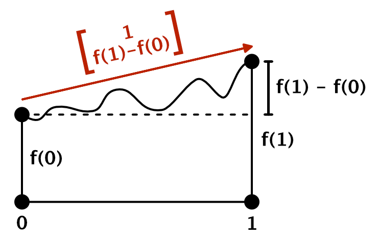
Unfortunately, we do not know what these functions are. But we can approximate them. We can compare the heights at two different points in our texture. For example, at the extreme ends, using U coordinates 0 and 1. The difference between those two samples is the rate of change between those coordinates. Expressed as a function, that's `f(1) - f(0)`. We can use this to construct a tangent vector, `[[1],[f(1) - f(0)],[0]]`.
That's of course a very crude approximation of the real tangent vector. It treats the entire texture as a linear slope. We can do better by sampling two points that are closer together. For example, U coordinates 0 and ½. The rate of change between those two points is `f(1/2) - f(0)`, per half a unit of U. Because it is easier to deal with rate of change per whole units, we divide it by the distance between the points, so we get `(f(1/2) - f(0))/(1/2) = 2(f(1/2) - f(0))`. That gives us the tangent vector `[[1],[2(f(1/2) - f(0))],[0]]`.
In general, we have to do this relative to the U coordinate of every fragment that we render. The distance to the next point is defined by a constant delta. So the derivative function is approximated by `f^'(u) ~~ (f(u + delta) - f(u))/delta`.
The smaller δ becomes, the better we approximate the true derivative function. Of course it cannot become zero, but when taken to its theoretical limit, you get `f^'(u) = lim_(delta->0)(f(u + delta) - f(u))/delta`. This method of approximating a derivative is known as the finite difference method. With that, we can construct tangent vectors at any point, `[[1],[f^'(u)],[0]]`.
From Tangent to Normal
What value could we use for δ in our shader? The smallest sensible difference would cover a single texel of our texture. We can retrieve this information in the shader via a float4 variable with the _TexelSize suffix. Unity sets those variables, similar to _ST variables.
sampler2D _HeightMap;
float4 _HeightMap_TexelSize;
Now we can sample the texture twice, compute the height derivative, and construct a tangent vector. Let's directly use that as our normal vector.
	float2 delta = float2(_HeightMap_TexelSize.x, 0);
	float h1 = tex2D(_HeightMap, i.uv);
	float h2 = tex2D(_HeightMap, i.uv + delta);
	i.normal = float3(1, (h2 - h1) / delta.x, 0);

	i.normal = normalize(i.normal);
Actually, because we're normalizing anyway, we can scale our tangent vector by δ. This eliminates a division and improves precision.
i.normal = float3(delta.x, h2 - h1, 0);
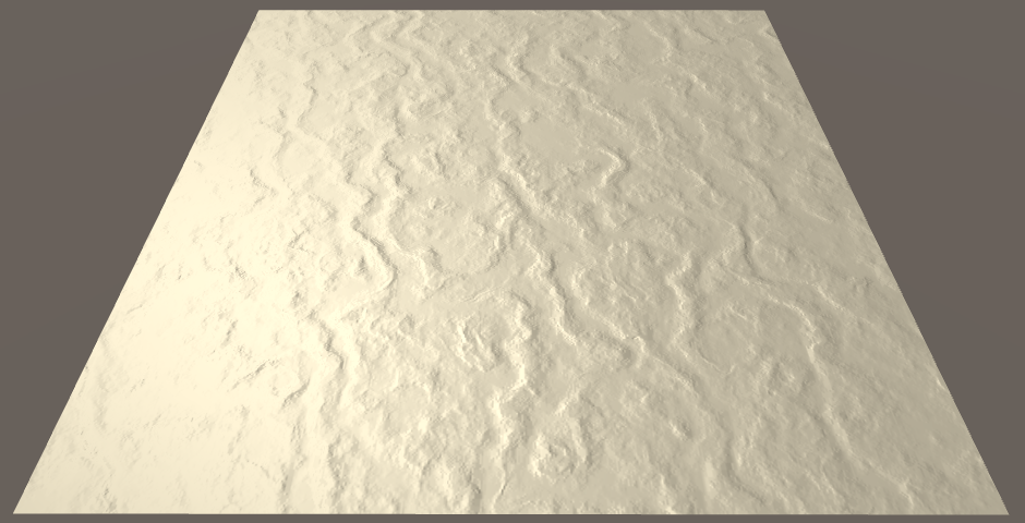
We get a very pronounced result. That's because the heights have a range of one unit, which produces very steep slopes. As the perturbed normals don't actually change the surface, we don't want such huge differences. We can scale the heights by an arbitrary factor. Let's reduce the range to a single texel. We can do that by multiplying the height difference by δ, or by simply replacing δ with 1 in the tangent.
i.normal = float3(1, h2 - h1, 0);
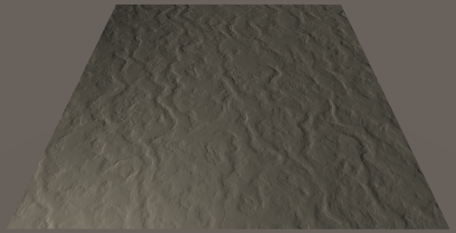
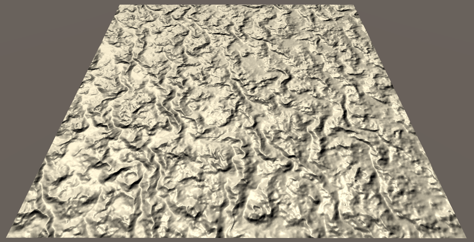
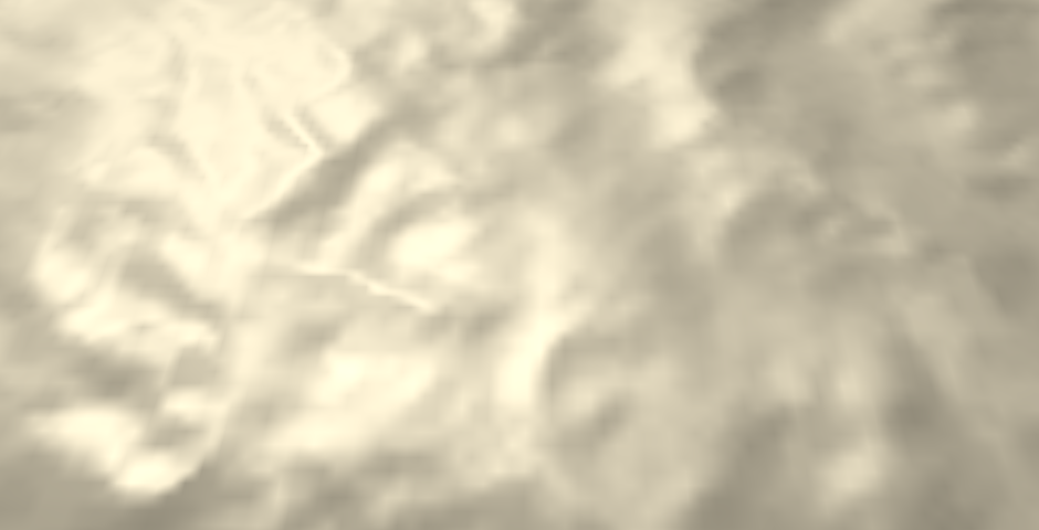
This is starting to look good, but the lighting is wrong. It is far too dark. That's because we're directly using the tangent as a normal. To turn it into an upward-pointing normal vector, we have to rotate the tangent 90° around the Z axis.
i.normal = float3(h1 - h2, 1, 0);
Central Difference
We've used finite difference approximations to create normal vectors. Specifically, by using the forward difference method. We take a point, and then look in one direction to determine the slope. As a result, the normal is biased in that direction. To get a better approximation of the normal, we can instead offset the sample points in both directions. This centers the linear approximation on the current point, and is known as the central difference method. This changes the derivative function to `f^'(u) = lim_(delta->0)(f(u + delta/2) - f(u - delta/2))/delta`.
	float2 delta = float2(_HeightMap_TexelSize.x * 0.5, 0);
	float h1 = tex2D(_HeightMap, i.uv - delta);
	float h2 = tex2D(_HeightMap, i.uv + delta);
	i.normal = float3(h1 - h2, 1, 0);
This shifts the bumps slightly, so they are better aligned with the height field. Besides that, their shape doesn't change.
Using Both Dimensions
The normals that we have created only take the change along U into account. We've been using the partial derivative of the function `f(u,v)` with respect to `u`. That's `f_u^'(u,v)`, or just `f_u^'` for short. We can also create normals along V, by using `f_v^'`. In that case, the tangent vector is `[[0],[f_v^'],[1]]` and the normal vector is `[[0],[1],[-f_v^']]`.
	float2 du = float2(_HeightMap_TexelSize.x * 0.5, 0);
	float u1 = tex2D(_HeightMap, i.uv - du);
	float u2 = tex2D(_HeightMap, i.uv + du);
	i.normal = float3(u1 - u2, 1, 0);

	float2 dv = float2(0, _HeightMap_TexelSize.y * 0.5);
	float v1 = tex2D(_HeightMap, i.uv - dv);
	float v2 = tex2D(_HeightMap, i.uv + dv);
	i.normal = float3(0, 1, v1 - v2);

	i.normal = normalize(i.normal);
We now have access to both the U and V tangents. Together, these vectors describe the surface of the height field at our fragment. By computing their cross product, we find the normal vector of the 2D height field.
	float2 du = float2(_HeightMap_TexelSize.x * 0.5, 0);
	float u1 = tex2D(_HeightMap, i.uv - du);
	float u2 = tex2D(_HeightMap, i.uv + du);
	float3 tu = float3(1, u2 - u1, 0);

	float2 dv = float2(0, _HeightMap_TexelSize.y * 0.5);
	float v1 = tex2D(_HeightMap, i.uv - dv);
	float v2 = tex2D(_HeightMap, i.uv + dv);
	float3 tv = float3(0, v2 - v1, 1);

	i.normal = cross(tv, tu);
	i.normal = normalize(i.normal);
When you calculate the cross product with the tangent vectors, you'll see that `[[0],[f_v^'],[1]] xx [[1],[f_u^'],[0]] = [[-f_u^'],[1],[-f_v^']]`. So we can construct the vector directly, instead of having to rely on the cross function.
void InitializeFragmentNormal(inout Interpolators i) {
	float2 du = float2(_HeightMap_TexelSize.x * 0.5, 0);
	float u1 = tex2D(_HeightMap, i.uv - du);
	float u2 = tex2D(_HeightMap, i.uv + du);
//	float3 tu = float3(1, u2 - u1, 0);

	float2 dv = float2(0, _HeightMap_TexelSize.y * 0.5);
	float v1 = tex2D(_HeightMap, i.uv - dv);
	float v2 = tex2D(_HeightMap, i.uv + dv);
//	float3 tv = float3(0, v2 - v1, 1);

//	i.normal = cross(tv, tu);
	i.normal = float3(u1 - u2, 1, v1 - v2);
	i.normal = normalize(i.normal);
}
Normal Mapping
While bump mapping works, we have to perform multiple texture samples and finite difference calculations. This seems like a waste, as the resulting normal should always be the same. Why do all this work every frame? We can do it once and store the normals in a texture.
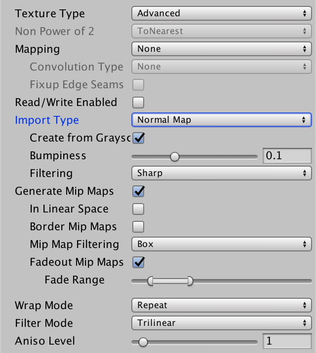
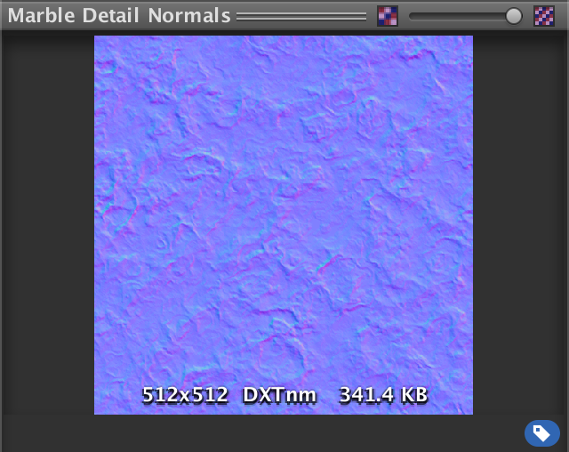
This means that we need a normal map. I could provide one, but we can let Unity do the work for us. Change the Texture Type of the height map to Normal Map. Unity automatically switches the texture to use trilinear filtering, and assumes that we want to use the grayscale image data to generate a normal map. This is exactly what we want, but change the Bumpiness to a much lower value, like 0.05.
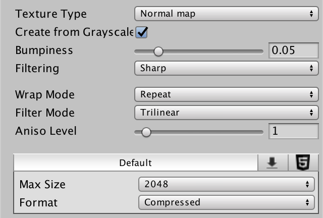
After applying the import settings, Unity will compute the normal map. The original height map still exists, but Unity internally uses the generated map.
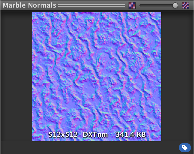
Like we did when visualizing normals as colors, they have to be adjusted to fit inside the 0–1 range. So they are stored as `(N + 1)/2`. This would suggest that flat areas will appear light green. However, they appear light blue instead. That's because the most common convention for normal maps is to store the up direction in the Z component. The Y and Z coordinates are swapped, from Unity's point of view.
Sampling the Normal Map
Because a normal map is quite different than a height map, rename the shader property accordingly.
	Properties {
		_Tint ("Tint", Color) = (1, 1, 1, 1)
		_MainTex ("Albedo", 2D) = "white" {}
		[NoScaleOffset] _NormalMap ("Normals", 2D) = "bump" {}
//		[NoScaleOffset] _HeightMap ("Heights", 2D) = "gray" {}
		[Gamma] _Metallic ("Metallic", Range(0, 1)) = 0
		_Smoothness ("Smoothness", Range(0, 1)) = 0.1
	}
We can remove all the height map code and replace it with a single texture sample, followed by a normalization.
sampler2D _NormalMap;//sampler2D _HeightMap;//float4 _HeightMap_TexelSize;… void InitializeFragmentNormal(inout Interpolators i) { i.normal = tex2D(_NormalMap, i.uv).rgb; i.normal = normalize(i.normal); }
Of course, we have to convert the normals back to their original −1–1 range, by computing `2N - 1`.
i.normal = tex2D(_NormalMap, i.uv).xyz * 2 - 1;
Also, make sure to swap Y and Z.
	i.normal = tex2D(_NormalMap, i.uv).xyz * 2 - 1;
	i.normal = i.normal.xzy;
DXT5nm
There is definitely something wrong with our normals. That's because Unity ended up encoding the normals in a different way than we expected. Even though the texture preview shows RGB encoding, Unity actually uses DXT5nm.
The DXT5nm format only stores the X and Y components of the normal. Its Z component is discarded. The Y component is stored in the G channel, as you might expect. However, the X component is stored in the A channel. The R and B channels are not used.
So when using DXT5nm, we can only retrieve the first two components of our normal.
i.normal.xy = tex2D(_NormalMap, i.uv).wy * 2 - 1;
We have to infer the third component from the other two. Because normals are unit vectors, `||N|| = ||N||^2 = N_x^2 + N_y^2 + N_z^2 = 1`. Thus `N_z = sqrt(1 - N_x^2 - N_y^2)`.
	i.normal.xy = tex2D(_NormalMap, i.uv).wy * 2 - 1;
	i.normal.z = sqrt(1 - dot(i.normal.xy, i.normal.xy));
	i.normal = i.normal.xzy;
Theoretically, the result should be equal to the original Z component. However, because the texture has limited precision, and because of texture filtering, the result will often be different. It's close enough, though.
Also, because of precision limitations, it is possible that `N_x^2 + N_y^2` ends up out of bounds. Make sure that this doesn't happen, by clamping the dot product.
i.normal.z = sqrt(1 - saturate(dot(i.normal.xy, i.normal.xy)));
Scaling Bumpiness
Because we bake the normals into a texture, we cannot scale them in the fragment shader. Or can we?
We can scale the normal's X and Y components before computing Z. If we decrease X and Y, then Z will become larger, resulting in a flatter surface. The opposite will happen if we increase them. So we can adjust the bumpiness that way. As we're already clamping the squares of X and Y, we'll never end up with invalid normals.
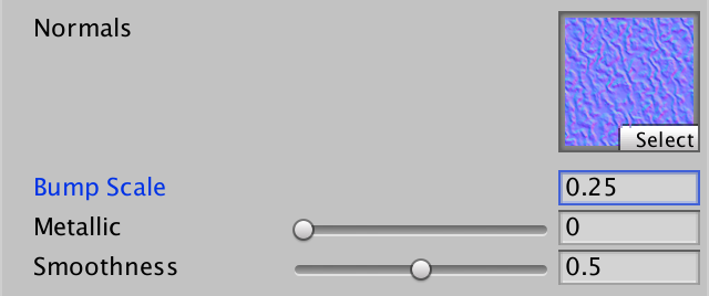
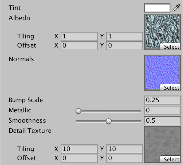
Let's add a bump scale property to our shader, just like Unity's standard shader.
	Properties {
		_Tint ("Tint", Color) = (1, 1, 1, 1)
		_MainTex ("Albedo", 2D) = "white" {}
		[NoScaleOffset] _NormalMap ("Normals", 2D) = "bump" {}
		_BumpScale ("Bump Scale", Float) = 1
		[Gamma] _Metallic ("Metallic", Range(0, 1)) = 0
		_Smoothness ("Smoothness", Range(0, 1)) = 0.1
	}
Incorporate this scale into our normal calculations.
sampler2D _NormalMap;
float _BumpScale;

…

void InitializeFragmentNormal(inout Interpolators i) {
	i.normal.xy = tex2D(_NormalMap, i.uv).wy * 2 - 1;
	i.normal.xy *= _BumpScale;
	i.normal.z = sqrt(1 - saturate(dot(i.normal.xy, i.normal.xy)));
	i.normal = i.normal.xzy;
	i.normal = normalize(i.normal);
}
To get bumps of about the same strength as we got while using the height map, reduce the scale to something like 0.25.
UnityStandardUtils contains the UnpackScaleNormal function. It automatically uses the correct decoding for normal maps, and scales normals as well. So let's take advantage of that convenient function.
void InitializeFragmentNormal(inout Interpolators i) {
//	i.normal.xy = tex2D(_NormalMap, i.uv).wy * 2 - 1;
//	i.normal.xy *= _BumpScale;
//	i.normal.z = sqrt(1 - saturate(dot(i.normal.xy, i.normal.xy)));
	i.normal = UnpackScaleNormal(tex2D(_NormalMap, i.uv), _BumpScale);
	i.normal = i.normal.xzy;
	i.normal = normalize(i.normal);
}
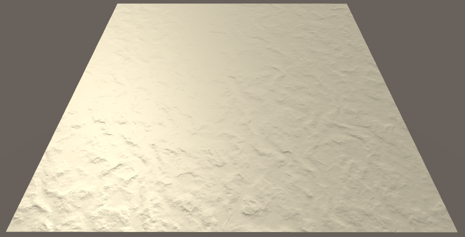
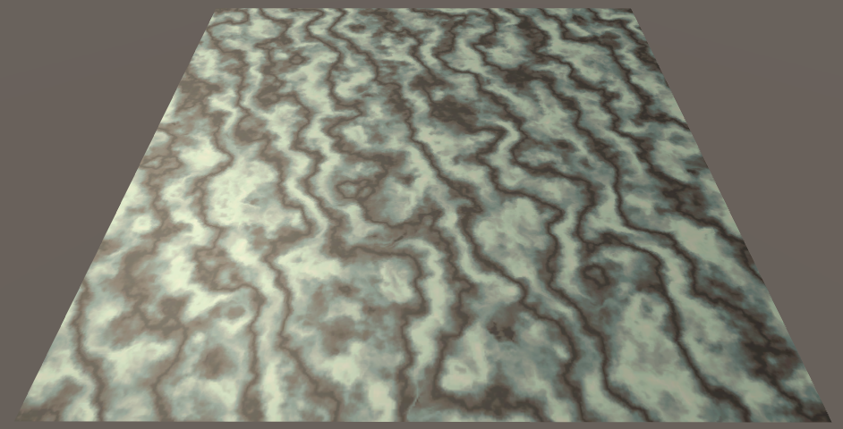
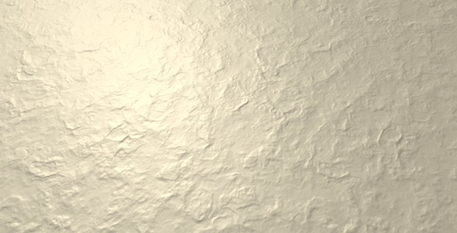
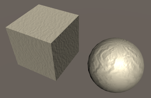
Combining Albedo and Bumps
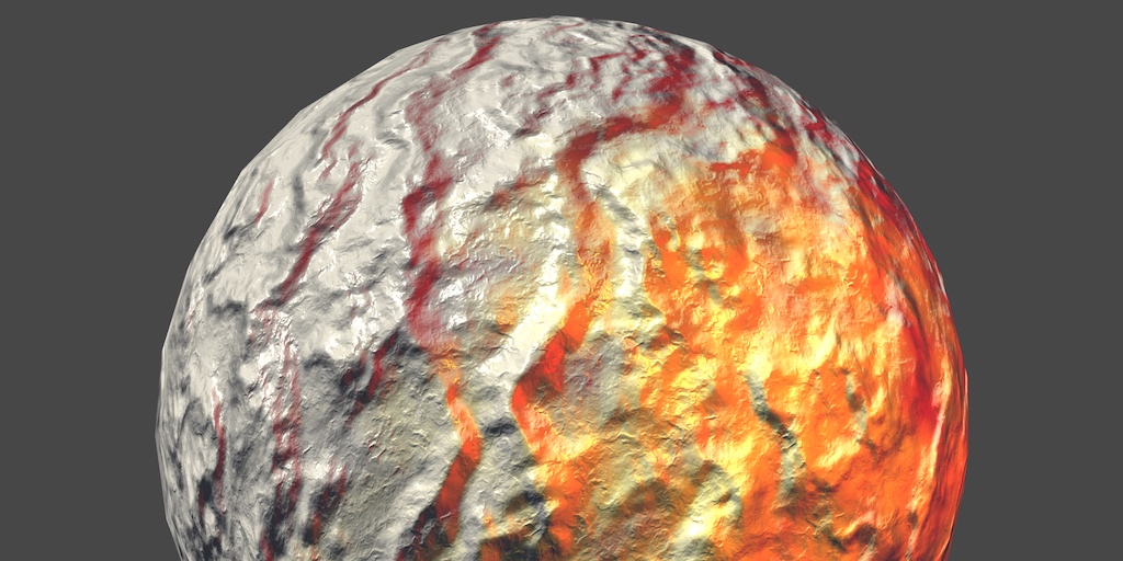
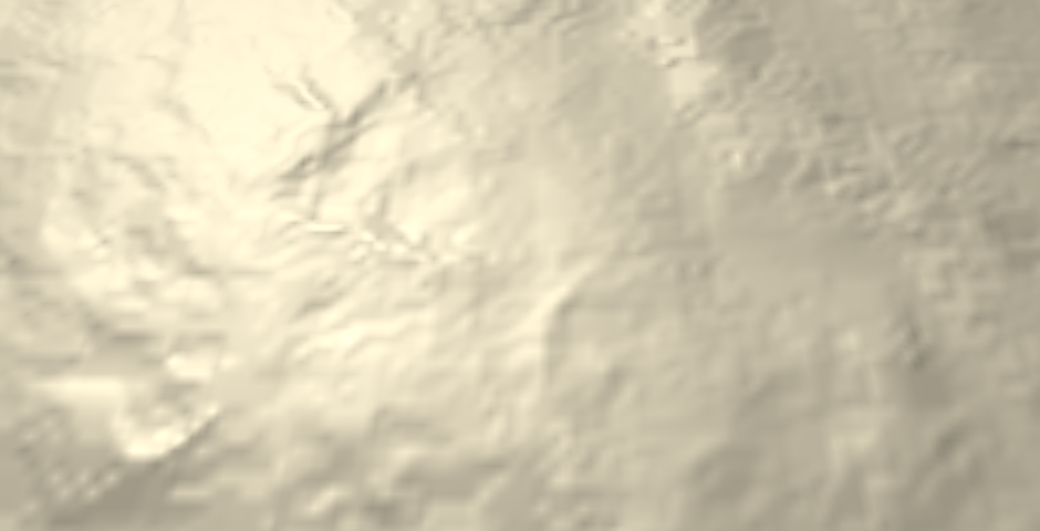
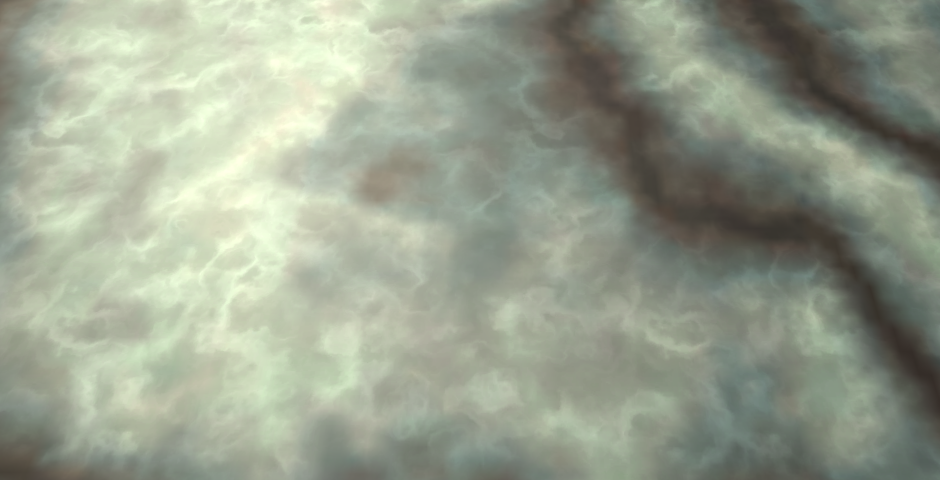
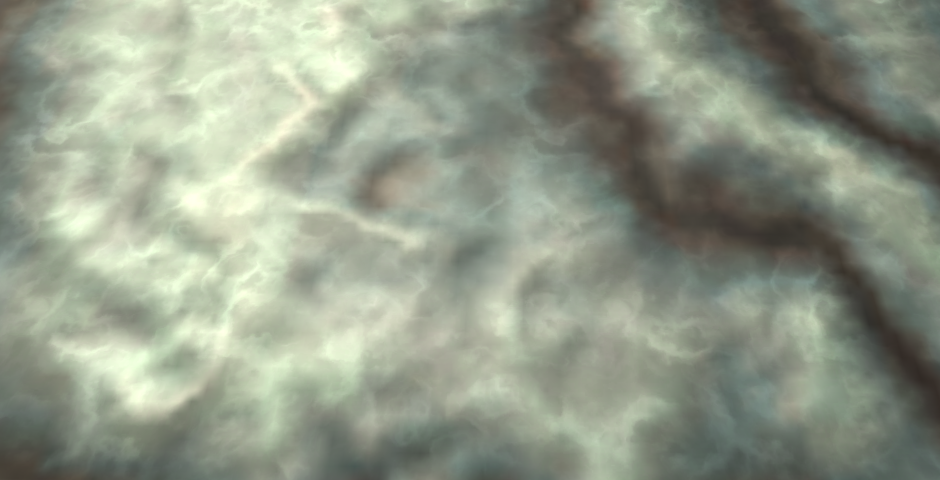
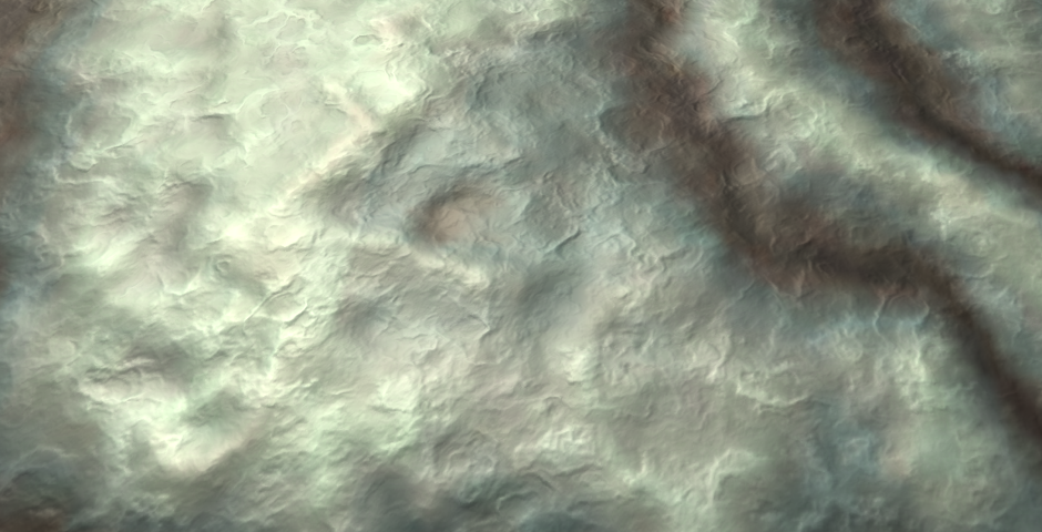
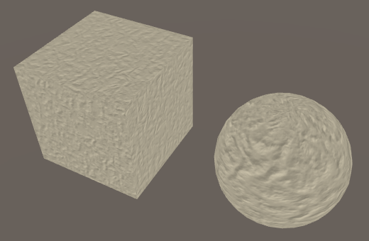
Now that we have a functional normal map, you can check the difference it makes. When only using the marble albedo texture, our quad looks like perfectly polished stone. Add the normal map, and it becomes a much more interesting surface.
Bump Details
In part 3, Combining Textures, we created a shader with a detail texture. We did this with the albedo, but we can also do it with bumps. First, add support for detail albedo to the My First Lighting Shader as well.
	Properties {
		_Tint ("Tint", Color) = (1, 1, 1, 1)
		_MainTex ("Albedo", 2D) = "white" {}
		[NoScaleOffset] _NormalMap ("Normals", 2D) = "bump" {}
		_BumpScale ("Bump Scale", Float) = 1
		[Gamma] _Metallic ("Metallic", Range(0, 1)) = 0
		_Smoothness ("Smoothness", Range(0, 1)) = 0.1
		_DetailTex ("Detail Texture", 2D) = "gray" {}
	}
Instead of adding an interpolator for the detail UV, let's manually pack both the main UV and detail UV in a single interpolator. The main UV go in XY, the detail UV go in ZW.
struct Interpolators {
	float4 position : SV_POSITION;
//	float2 uv : TEXCOORD0;
	float4 uv : TEXCOORD0;
	float3 normal : TEXCOORD1;
	float3 worldPos : TEXCOORD2;

	#if defined(VERTEXLIGHT_ON)
		float3 vertexLightColor : TEXCOORD3;
	#endif
};
Add the required variables and fill the interpolator in the vertex program.
sampler2D _MainTex, _DetailTex;
sampler2D _MainTex, _DetailTex;
float4 _MainTex_ST, _DetailTex_ST;

…

Interpolators MyVertexProgram (VertexData v) {
	Interpolators i;
	i.position = mul(UNITY_MATRIX_MVP, v.position);
	i.worldPos = mul(unity_ObjectToWorld, v.position);
	i.normal = UnityObjectToWorldNormal(v.normal);
	i.uv.xy = TRANSFORM_TEX(v.uv, _MainTex);
	i.uv.zw = TRANSFORM_TEX(v.uv, _DetailTex);
	ComputeVertexLightColor(i);
	return i;
}
Now we have should use i.uv.xy instead of i.uv, when we need the main UV.
void InitializeFragmentNormal(inout Interpolators i) {
	i.normal = UnpackScaleNormal(tex2D(_NormalMap, i.uv.xy), _BumpScale);
	i.normal = i.normal.xzy;
	i.normal = normalize(i.normal);
}

float4 MyFragmentProgram (Interpolators i) : SV_TARGET {
	InitializeFragmentNormal(i);

	float3 viewDir = normalize(_WorldSpaceCameraPos - i.worldPos);

	float3 albedo = tex2D(_MainTex, i.uv.xy).rgb * _Tint.rgb;

	…
}
Factor the detail texture into the albedo.
	float3 albedo = tex2D(_MainTex, i.uv.xy).rgb * _Tint.rgb;
	albedo *= tex2D(_DetailTex, i.uv.zw) * unity_ColorSpaceDouble;
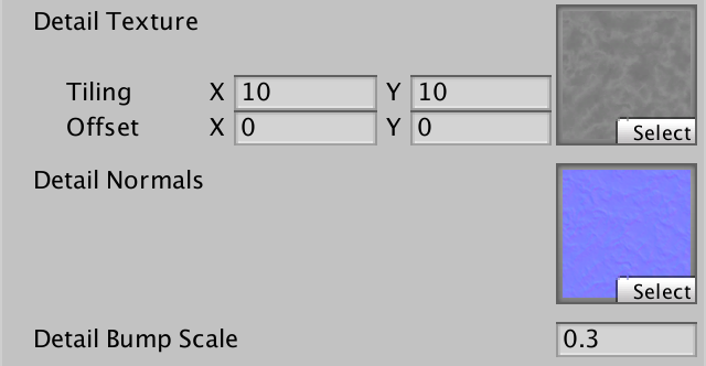
Detail Normals
As the detail texture of our marble material is grayscale, we can use it to generate a normal map. Duplicate it and change its Import Type to Normal Map. Decrease its Bumpiness to something like 0.1 and leave all other settings as they were.
As we're fading out the mipmaps, the colors fade to gray. As a result, the detail normal map that Unity generates fades to flat. So they fade out together.
Add a property for the detail normal map to our shader. Give it a bump scale as well.
	Properties {
		_Tint ("Tint", Color) = (1, 1, 1, 1)
		_MainTex ("Albedo", 2D) = "white" {}
		[NoScaleOffset] _NormalMap ("Normals", 2D) = "bump" {}
		_BumpScale ("Bump Scale", Float) = 1
		[Gamma] _Metallic ("Metallic", Range(0, 1)) = 0
		_Smoothness ("Smoothness", Range(0, 1)) = 0.1
		_DetailTex ("Detail Texture", 2D) = "gray" {}
		[NoScaleOffset] _DetailNormalMap ("Detail Normals", 2D) = "bump" {}
		_DetailBumpScale ("Detail Bump Scale", Float) = 1
	}
Add the required variables and fetch the detail normal map, just like the main normal map. Before we combine them, show just the detail normal.
sampler2D _NormalMap, _DetailNormalMap;
float _BumpScale, _DetailBumpScale;

…

void InitializeFragmentNormal(inout Interpolators i) {
	i.normal = UnpackScaleNormal(tex2D(_NormalMap, i.uv.xy), _BumpScale);
	i.normal =
		UnpackScaleNormal(tex2D(_DetailNormalMap, i.uv.zw), _DetailBumpScale);
	i.normal = i.normal.xzy;
	i.normal = normalize(i.normal);
}
Blending Normals
We combined the main and detail albedo by multiplying them together. We cannot do this with normals, because they are vectors. But we could average them, before normalizing.
void InitializeFragmentNormal(inout Interpolators i) {
	float3 mainNormal =
		UnpackScaleNormal(tex2D(_NormalMap, i.uv.xy), _BumpScale);
	float3 detailNormal =
		UnpackScaleNormal(tex2D(_DetailNormalMap, i.uv.zw), _DetailBumpScale);
	i.normal = (mainNormal + detailNormal) * 0.5;
	i.normal = i.normal.xzy;
	i.normal = normalize(i.normal);
}
The result isn't very good. Both the main and detail bumps get flattened. Ideally, when one of them is flat, it shouldn't affect the other at all.
What we're effectively trying to do here, is combine two height fields. Averaging those makes no sense. It makes a lot more sense to add them. When adding two height functions, their slopes – thus their derivatives – are added as well. Can we extract the derivatives from the normals?
Earlier, we constructed our own normal vector by normalizing `[[-f_u^'],[1],[-f_v^']]`. Our normal maps contain normals of the same type, except with their Y and Z components swapped. So they're of the form `[[-f_u^'],[-f_v^'],[1]]`. However, these normals have been scaled by the normalization process. So we start with `[[-s f_u^'],[-s f_v^'],[s]]`, where `s` is an arbitrary scale factor. The Z component is equal to this factor. This means that we can find the partial derivatives by dividing X and Y by Z. This only fails when Z is zero, which corresponds with a vertical surface. Our bumps are nowhere near that steep, so we don't need to worry about that.
Once we have the derivatives, we can add them to find the derivatives of the summed height fields. Then, we convert back to a normal vector. The resulting vector, before normalizing, is `[[M_x/M_z + D_x/D_z],[M_y/M_z + D_y/D_z],[1]]`.
void InitializeFragmentNormal(inout Interpolators i) {
	float3 mainNormal =
		UnpackScaleNormal(tex2D(_NormalMap, i.uv.xy), _BumpScale);
	float3 detailNormal =
		UnpackScaleNormal(tex2D(_DetailNormalMap, i.uv.zw), _DetailBumpScale);
	i.normal =
		float3(mainNormal.xy / mainNormal.z + detailNormal.xy / detailNormal.z, 1);
	i.normal = i.normal.xzy;
	i.normal = normalize(i.normal);
}
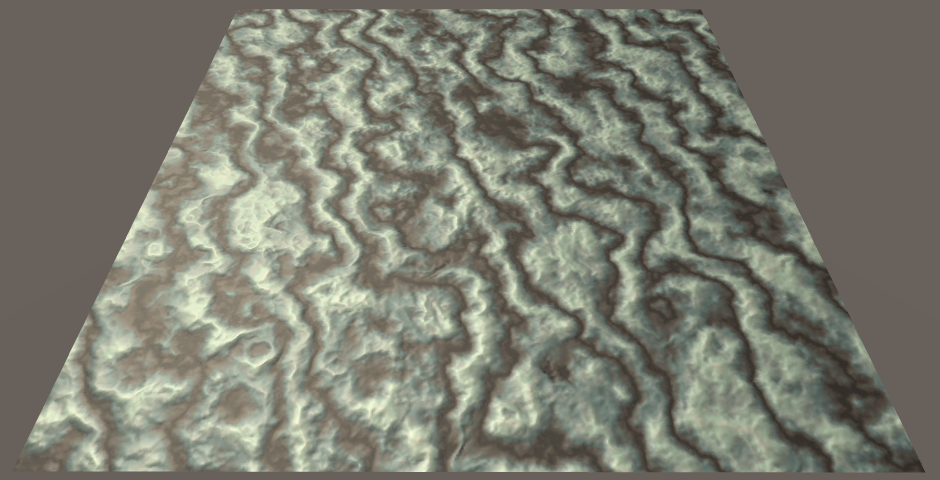
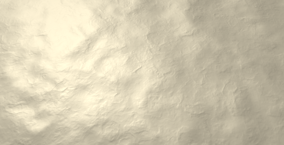
This produces a much better result! It works quite well when combining maps that are mostly flat. However, combining steep slopes will still lose details. A slightly alternative method is whiteout blending. First, multiply the new normal by `M_zD_z`. We can do this, because we normalize afterwards anyway. This gives us the vector `[[M_xD_z + D_xM_z],[M_yD_z + D_yM_z],[M_zD_z]]`. Then drop the scaling of X and Y, leading to `[[M_x + D_x],[M_y + D_y],[M_zD_z]]`.
This tweak exaggerates the X and Y components, and thus produces more pronounced bumps along steep slopes. But when one of the normals is flat, the other normal is not altered.
i.normal = float3(mainNormal.xy + detailNormal.xy, mainNormal.z * detailNormal.z);// float3(mainNormal.xy / mainNormal.z + detailNormal.xy / detailNormal.z, 1);
UnityStandardUtils contains the BlendNormals function, which also uses whiteout blending. So let's that function. It also normalizes the result, so we don't have to do that ourselves anymore.
i.normal = BlendNormals(mainNormal, detailNormal);// float3(mainNormal.xy + detailNormal.xy, mainNormal.z * detailNormal.z);i.normal = i.normal.xzy;// i.normal = normalize(i.normal);
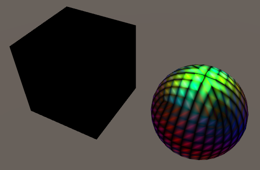
Tangent Space
Up to this points, we have assumed that we're shading a flat surface that is aligned with the XZ plane. But for this technique to be of any use, it must work for arbitrary geometry.
One of the faces of a cube can be aligned so that it matches our assumptions. We could support the other sides, by swapping and flipping dimensions. But this assumes a cube that is axis-aligned. When the cube has an arbitrary rotation, it becomes more complex. We have to transform the results of our bump mapping code so it matches the real orientation of the face.
Can we know the orientation of a face? For that, we need vectors that define the U and V axes. Those two, plus the normal vector, define a 3D space which matches our assumptions. Once we have that space, we can use it to transform the bumps to world space.
As we already have the normal vector `N`, we only require one additional vector. The cross product of those two vectors defines the third one.
The additional vector is provided as part of the mesh's vertex data. As it lies in the plane defined by the surface normal, it is known as the tangent vector `T`. By convention, this vector matches the U axis, pointing to the right.
The third vector is known as `B`, the bitangent, or the binormal. As Unity refers to it as the binormal, so will I. This vector defines the V axis, pointing forward. The standard way to derive the bitangent is via `B = N xx T`. However, this will produce a vector that points backwards, not forwards. To correct this, the result has to be multiplied with −1. This factor is stored as an extra fourth component of `T`.
So we can use the vertex normal and tangent to construct a 3D space that matches the mesh surface. This space is known as tangent space, the tangent basis, or TBN space. In the case of a cube, tangent space is uniform per face. In the case of a sphere, tangent space wraps around its surface.
In order to construct this space, the mesh has to contain tangent vectors. Fortunately, Unity's default meshes contain this data. When importing a mesh into Unity, you either import your own tangents, or have Unity generate them for you.
Visualizing Tangent Space
To get an idea of how tangent space works, let's code a quick visualization of it. Create a TangentSpaceVisualizer component with an OnDrawGizmos method.
using UnityEngine;

public class TangentSpaceVisualizer : MonoBehaviour {

	void OnDrawGizmos () {
	}
}
Each time gizmos are drawn, grab the mesh from the game object's mesh filter, and use it to show its tangent space. Of course this only works if there actually is a mesh. Grab the shadedMesh, not the mesh. The first gives us a reference to the mesh asset, while the second would create a copy.
	void OnDrawGizmos () {
		MeshFilter filter = GetComponent<MeshFilter>();
		if (filter) {
			Mesh mesh = filter.sharedMesh;
			if (mesh) {
				ShowTangentSpace(mesh);
			}
		}
	}

	void ShowTangentSpace (Mesh mesh) {
	}
First, we'll show the normal vectors. Get the vertex positions and normals from the mesh, and use those to draw lines. We have to transform them to world space so they match the geometry in the scene. As the normal corresponds with the up direction in tangent space, let's give them a green color.
	void ShowTangentSpace (Mesh mesh) {
		Vector3[] vertices = mesh.vertices;
		Vector3[] normals = mesh.normals;
		for (int i = 0; i < vertices.Length; i++) {
			ShowTangentSpace(
				transform.TransformPoint(vertices[i]),
				transform.TransformDirection(normals[i])
			);
		}
	}

	void ShowTangentSpace (Vector3 vertex, Vector3 normal) {
		Gizmos.color = Color.green;
		Gizmos.DrawLine(vertex, vertex + normal);
	}
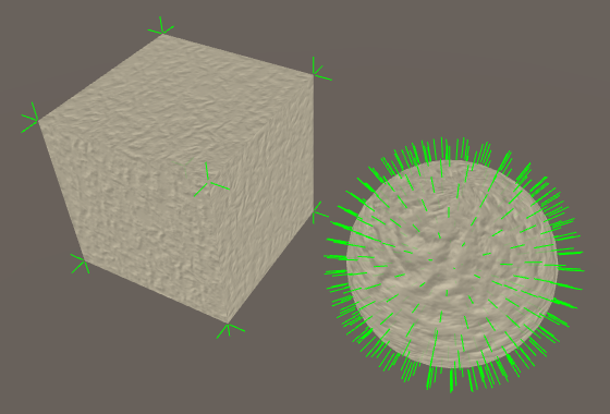
Add this component to some objects with a mesh to see their vertex normals.
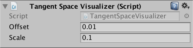
What is a sensible length of the lines? It depends on the geometry. So let's add a configurable scale. Let's also support a configurable offset, which pushes the lines away from the surface. That makes it easier to inspect overlapping vertices.
	public float offset = 0.01f;
	public float scale = 0.1f;

	void ShowTangentSpace (Vector3 vertex, Vector3 normal) {
		vertex += normal * offset;
		Gizmos.color = Color.green;
		Gizmos.DrawLine(vertex, vertex + normal * scale);
	}
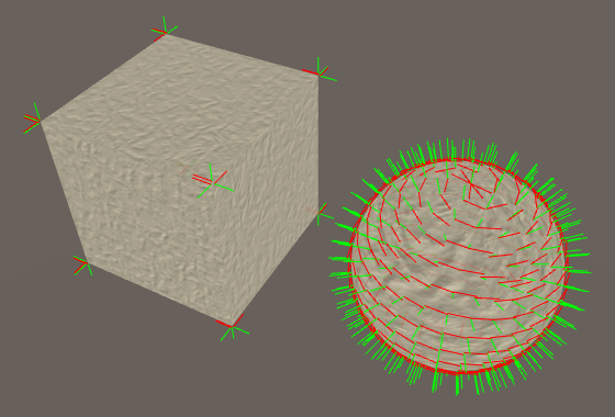
Now include the tangent vectors. They works just like normal vectors, except that they're 4D vectors. As they point rightward locally, give them a red color.
	void ShowTangentSpace (Mesh mesh) {
		Vector3[] vertices = mesh.vertices;
		Vector3[] normals = mesh.normals;
		Vector4[] tangents = mesh.tangents;
		for (int i = 0; i < vertices.Length; i++) {
			ShowTangentSpace(
				transform.TransformPoint(vertices[i]),
				transform.TransformDirection(normals[i]),
				transform.TransformDirection(tangents[i])
			);
		}
	}

	void ShowTangentSpace (Vector3 vertex, Vector3 normal, Vector3 tangent) {
		vertex += normal * offset;
		Gizmos.color = Color.green;
		Gizmos.DrawLine(vertex, vertex + normal * scale);
		Gizmos.color = Color.red;
		Gizmos.DrawLine(vertex, vertex + tangent * scale);
	}
Finally, construct and show the binormal vectors with a blue line.
	void ShowTangentSpace (Mesh mesh) {
		…
		for (int i = 0; i < vertices.Length; i++) {
			ShowTangentSpace(
				transform.TransformPoint(vertices[i]),
				transform.TransformDirection(normals[i]),
				transform.TransformDirection(tangents[i]),
				tangents[i].w
			);
		}
	}

	void ShowTangentSpace (
		Vector3 vertex, Vector3 normal, Vector3 tangent, float binormalSign
	) {
		…
		Vector3 binormal = Vector3.Cross(normal, tangent) * binormalSign;
		Gizmos.color = Color.blue;
		Gizmos.DrawLine(vertex, vertex + binormal * scale);
	}
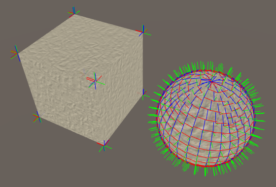
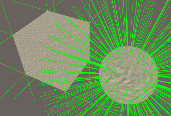
You can see that the tangent space is different but constant for each face of a default cube. In case of a default sphere, the tangent space is different for each vertex. As as result, the tangent space will be interpolated across triangles, resulting in a curved space.
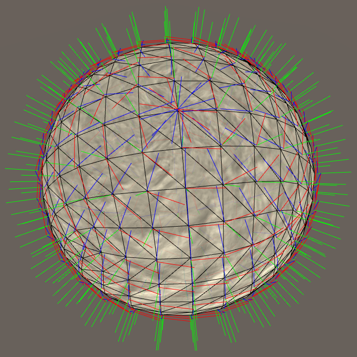
Wrapping tangent space around a sphere is problematic. Unity's default sphere uses the longitude-latitude texture layout. It's like wrapping a piece of paper around a ball, forming a cylinder. Then, the top and bottom of the cylinder are crumpled until they match the sphere. So the poles are quite messy. Unity's default sphere combines that with a cubic vertex layout, which exacerbates the problem. They're fine for mock-ups, but don't expect the default meshes to produce high-quality results.
Tangent Space in the Shader
To access the tangents in our shader, we have to add them to the VertexData struct.
struct VertexData {
	float4 position : POSITION;
	float3 normal : NORMAL;
	float4 tangent : TANGENT;
	float2 uv : TEXCOORD0;
};
And we have to include them as an additional interpolator. The order of the interpolators doesn't matter, but I like to keep the normal and tangent together.
struct Interpolators {
	float4 position : SV_POSITION;
	float4 uv : TEXCOORD0;
	float3 normal : TEXCOORD1;
	float4 tangent : TEXCOORD2;
	float3 worldPos : TEXCOORD3;

	#if defined(VERTEXLIGHT_ON)
		float3 vertexLightColor : TEXCOORD4;
	#endif
};
Transform the tangent to world space in the vertex program, using UnityObjectToWorldDir from UnityCG. Of course this only applies to the XYZ part of the tangent. Its W component needs to be passed along unmodified.
Interpolators MyVertexProgram (VertexData v) {
	Interpolators i;
	i.position = mul(UNITY_MATRIX_MVP, v.position);
	i.worldPos = mul(unity_ObjectToWorld, v.position);
	i.normal = UnityObjectToWorldNormal(v.normal);
	i.tangent = float4(UnityObjectToWorldDir(v.tangent.xyz), v.tangent.w);
	i.uv.xy = TRANSFORM_TEX(v.uv, _MainTex);
	i.uv.zw = TRANSFORM_TEX(v.uv, _DetailTex);
	ComputeVertexLightColor(i);
	return i;
}
We now have access to both the normal and the tangent in the fragment shader. So we can construct the binormal in InitializeFragmentNormal. However, we must take care to not replace the original normal with the bumped normal. The bumped normal exists in tangent space, so keep it separate.
void InitializeFragmentNormal(inout Interpolators i) {
	float3 mainNormal =
		UnpackScaleNormal(tex2D(_NormalMap, i.uv.xy), _BumpScale);
	float3 detailNormal =
		UnpackScaleNormal(tex2D(_DetailNormalMap, i.uv.zw), _DetailBumpScale);
	float3 tangentSpaceNormal = BlendNormals(mainNormal, detailNormal);
	tangentSpaceNormal = tangentSpaceNormal.xzy;

	float3 binormal = cross(i.normal, i.tangent.xyz) * i.tangent.w;
}
Now we can convert the bumped normal from tangent space to world space.
	float3 binormal = cross(i.normal, i.tangent.xyz) * i.tangent.w;

	i.normal = normalize(
		tangentSpaceNormal.x * i.tangent +
		tangentSpaceNormal.y * i.normal +
		tangentSpaceNormal.z * binormal
	);
We can also get rid of the explicit YZ swap, combining it with the space conversion.
// tangentSpaceNormal = tangentSpaceNormal.xzy;float3 binormal = cross(i.normal, i.tangent.xyz) * i.tangent.w; i.normal = normalize( tangentSpaceNormal.x * i.tangent + tangentSpaceNormal.y * binormal + tangentSpaceNormal.z * i.normal ;
There is one additional detail, when constructing the binormal. Suppose an object has its scale set to (-1, 1, 1). That means that it is mirrored. We have to flip the binormal in this case, to correctly mirror the tangent space as well. In fact, we have to do this when an odd number of dimensions are negative. UnityShaderVariables helps us with this, by defining the float4 unity_WorldTransformParams variable. Its fourth component contains −1 when we need to flip the binormal, and 1 otherwise.
	float3 binormal = cross(i.normal, i.tangent.xyz) *
		(i.tangent.w * unity_WorldTransformParams.w);
Synched Tangent Space
When a 3D artist creates a detailed model, the usual approach is to build a very high-resolution model. All the details are actual 3D geometry. To make this work in a game, a low-resolution version of the model is generated. The details are baked into textures for this model.
The normals of the high-resolution model are baked into a normal map. This is done by converting the normals from world space to tangent space. When rendering the low-resolution model in a game, this conversion is reversed.
This process works fine, as long as both conversions use the same algorithm and tangent space. When they don't, the in-game results will be wrong. This can cause 3D artists a lot of grief. So you have to make sure that your normal map generator, Unity's mesh import process, and the shader are all synchronized. This is known as a synched tangent space workflow.
Since version 5.3, Unity uses mikktspace. So make sure that you're using mikktspace as well when generating your normal maps. When importing a mesh, you can allow Unity to generate the tangent vectors for you, as it uses the mikktspace algorithm for that. Alternatively, export mikktspace tangents yourself and have Unity use those.
When using mikktspace, there is one choice to make. The binormal can either be constructed in the fragment program – like we do – or in the vertex program – like Unity does. Both approaches produce slightly different binormals.
So when generating your normal map for Unity, use settings that corresponds with calculating binormals per vertex. Or go ahead and assume they're calculated per fragment, and use a shader that does so as well.
Binormals Per Vertex or Fragment
If we want to be consistent with Unity's standard shaders, we have to calculate the binormal per vertex. The upside of doing that is that we don't have to compute a cross product in the fragment shader. The downside is that we need an additional interpolator.
If you're not sure which method to use, you can always support both. Let's say that if BINORMAL_PER_FRAGMENT is defined, we calculate the binormal per fragment. Otherwise, we do it per vertex. In the former case, we keep our float4 tangent interpolator. In the latter, we need two float3 interpolators instead.
struct Interpolators {
	float4 position : SV_POSITION;
	float4 uv : TEXCOORD0;
	float3 normal : TEXCOORD1;

	#if defined(BINORMAL_PER_FRAGMENT)
		float4 tangent : TEXCOORD2;
	#else
		float3 tangent : TEXCOORD2;
		float3 binormal : TEXCOORD3;
	#endif

	float3 worldPos : TEXCOORD4;

	#if defined(VERTEXLIGHT_ON)
		float3 vertexLightColor : TEXCOORD5;
	#endif
};
Let's put the binormal calculation in its own function. We can then use it in either the vertex or the fragment shader.
float3 CreateBinormal (float3 normal, float3 tangent, float binormalSign) {
	return cross(normal, tangent.xyz) *
		(binormalSign * unity_WorldTransformParams.w);
}

Interpolators MyVertexProgram (VertexData v) {
	Interpolators i;
	i.position = mul(UNITY_MATRIX_MVP, v.position);
	i.worldPos = mul(unity_ObjectToWorld, v.position);
	i.normal = UnityObjectToWorldNormal(v.normal);

	#if defined(BINORMAL_PER_FRAGMENT)
		i.tangent = float4(UnityObjectToWorldDir(v.tangent.xyz), v.tangent.w);
	#else
		i.tangent = UnityObjectToWorldDir(v.tangent.xyz);
		i.binormal = CreateBinormal(i.normal, i.tangent, v.tangent.w);
	#endif

	i.uv.xy = TRANSFORM_TEX(v.uv, _MainTex);
	i.uv.zw = TRANSFORM_TEX(v.uv, _DetailTex);
	ComputeVertexLightColor(i);
	return i;
}

…

void InitializeFragmentNormal(inout Interpolators i) {
	float3 mainNormal =
		UnpackScaleNormal(tex2D(_NormalMap, i.uv.xy), _BumpScale);
	float3 detailNormal =
		UnpackScaleNormal(tex2D(_DetailNormalMap, i.uv.zw), _DetailBumpScale);
	float3 tangentSpaceNormal = BlendNormals(mainNormal, detailNormal);

	#if defined(BINORMAL_PER_FRAGMENT)
		float3 binormal = CreateBinormal(i.normal, i.tangent.xyz, i.tangent.w);
	#else
		float3 binormal = i.binormal;
	#endif

	i.normal = normalize(
		tangentSpaceNormal.x * i.tangent +
		tangentSpaceNormal.y * binormal +
		tangentSpaceNormal.z * i.normal
	);
}
As BINORMAL_PER_FRAGMENT is not defined anywhere, our shader will now calculate the binormals per vertex. If you want to calculate them per fragment, you have to define BINORMAL_PER_FRAGMENT somewhere. You can consider this a configuration option of our include file. As such, it makes sense to define it inside My First Lighting Shader, before including My Lighting.
As it makes sense to use the same setting for all our passes, we have to define it in both the base and the additive pass. But we can also put it inside a CGINCLUDE block at the top of our shader. The contents of that block is included inside all CGPROGRAM blocks.
	Properties {
		…
	}

	CGINCLUDE

	#define BINORMAL_PER_FRAGMENT

	ENDCG

	SubShader {
		…
	}
You can verify that this works by inspecting the compiled shader code. For example, here are the interpolators used by D3D11, without BINORMAL_PER_FRAGMENT defined.
// Output signature:
//
// Name                 Index   Mask Register SysValue  Format   Used
// -------------------- ----- ------ -------- -------- ------- ------
// SV_POSITION              0   xyzw        0      POS   float   xyzw
// TEXCOORD                 0   xyzw        1     NONE   float   xyzw
// TEXCOORD                 1   xyz         2     NONE   float   xyz
// TEXCOORD                 2   xyz         3     NONE   float   xyz
// TEXCOORD                 3   xyz         4     NONE   float   xyz
// TEXCOORD                 4   xyz         5     NONE   float   xyz
And here they are, when BINORMAL_PER_FRAGMENT is defined.
// Output signature:
//
// Name                 Index   Mask Register SysValue  Format   Used
// -------------------- ----- ------ -------- -------- ------- ------
// SV_POSITION              0   xyzw        0      POS   float   xyzw
// TEXCOORD                 0   xyzw        1     NONE   float   xyzw
// TEXCOORD                 1   xyz         2     NONE   float   xyz
// TEXCOORD                 2   xyzw        3     NONE   float   xyzw
// TEXCOORD                 4   xyz         4     NONE   float   xyz
The next tutorial is Shadows.