Custom Render Pipeline
Taking Control of Rendering
- Create a render pipeline asset and instance.
- Render a camera's view.
- Perform culling, filtering, and sorting.
- Separate opaque, transparent, and invalid passes.
- Work with more than one camera.
This is the first part of a tutorial series about creating a custom scriptable render pipeline. It covers the initial creation of a bare-bones render pipeline that we will expand in the future.
This is an expert-level series that assumes that you've worked through or are already familiar with the concepts introduced in multiple other series. If you've worked through Procedural Meshes and its prerequisites you should be good to go.
This tutorial is made with Unity 2019.2.6f1 and upgraded to 2022.3.5f1. Things in this series might look a little different from Unity 2022 as it was made with Unity 2019, but everything still works. I have indicated the few upgrade changes that were necessary.
A new Render Pipeline
To render anything, Unity has to determine what shapes have to be drawn, where, when, and with what settings. This can get very complex, depending on how many effects are involved. Lights, shadows, transparency, image effects, volumetric effects, and so on all have to be dealt with in the correct order to arrive at the final image. This is what a render pipeline does.
In the past Unity only supported a few built-in ways to render things. Unity 2018 introduced scriptable render pipelines—RPs for short—making it possible to do whatever we want, while still being able to rely on Unity for fundamental steps like culling. Unity 2018 also added two experimental RPs made with this new approach: the Lightweight RP and the High Definition RP. In Unity 2019 the Lightweight RP is no longer experimental and got rebranded to the Universal RP in Unity 2019.3.
The Universal RP is destined to replace the current legacy RP as the default. The idea is that it is a one-size-fits-most RP that will also be fairly easy to customize. Rather than customizing that RP this series will create an entire RP from scratch.
This tutorial lays the foundation with a minimal RP that draws unlit shapes using forward rendering. Once that's working, we can extend our pipeline in later tutorials, adding lighting, shadows, different rendering methods, and more advanced features.
Project Setup
Create a new 3D project in Unity 2022.3.5f1 (used to be 2019.2.6) or later. We'll create our own pipeline, so don't select one of the RP project templates. Once the project is open you can go to the package manager and remove all packages that you don't need. We'll only use the Unity UI package in this tutorial to experiment with drawing the UI, so you can keep that one.
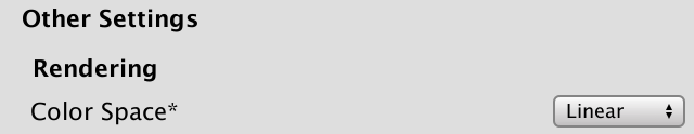
We're going to exclusively work in linear color space, but Unity 2019.2 still uses gamma space as the default. Go to the player settings via Edit / Project Settings and then Player, then switch Color Space under the Other Settings section to Linear.
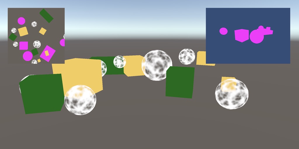
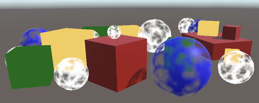
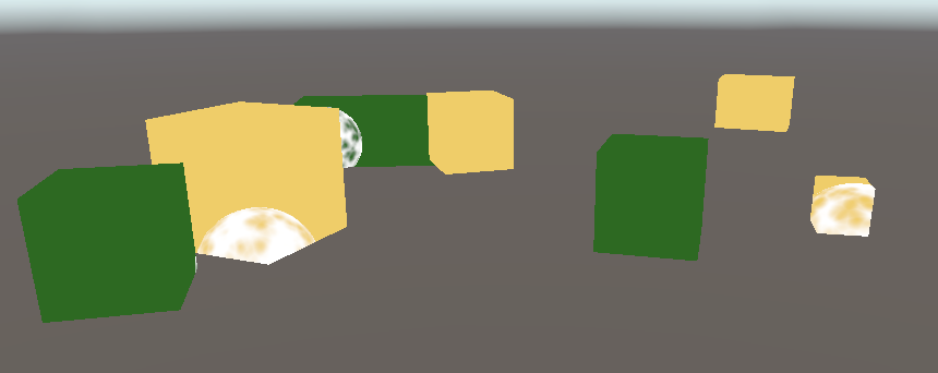
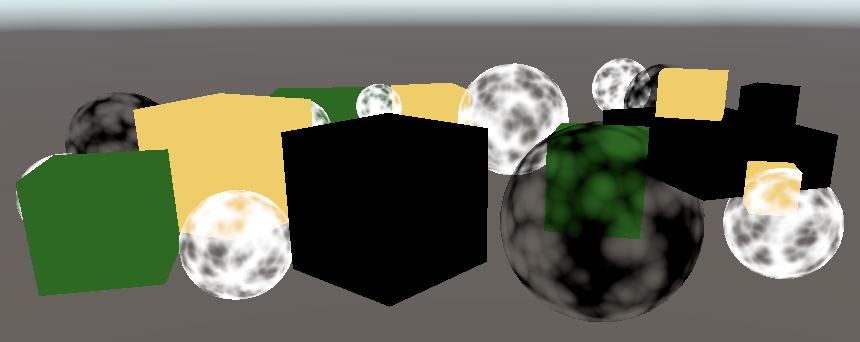
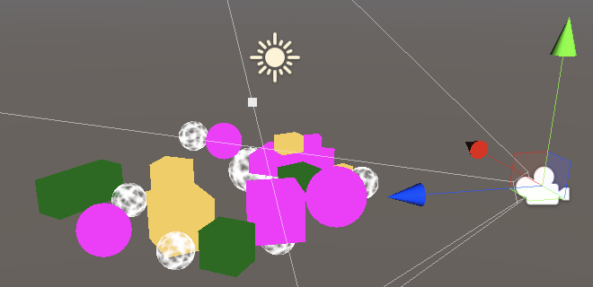
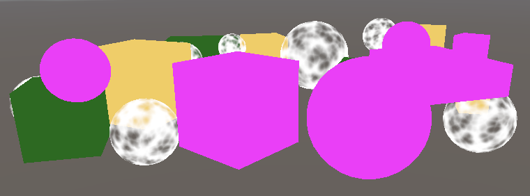
Fill the default scene with a few objects, using a mix of standard, unlit opaque and transparent materials. The Unlit/Transparent shader only works with a texture, so here is a UV sphere map for that.

I put a few cubes in my test scene, all of which are opaque. The red ones use a material with the Standard shader while the green and yellow ones use a material with the Unlit/Color shader. The blue spheres use the Standard shader with Rendering Mode set to Transparent, while the white spheres use the Unlit/Transparent shader.
Pipeline Asset
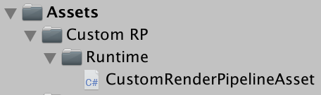
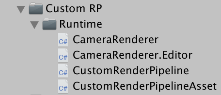
Currently, Unity uses the default render pipeline. To replace it with a custom render pipeline we first have to create an asset type for it. We'll use roughly the same folder structure that Unity uses for the Universal RP. Create a Custom RP asset folder with a Runtime child folder. Put a new C# script in there for the CustomRenderPipelineAsset type.
The asset type must extend RenderPipelineAsset from the UnityEngine.Rendering namespace.
using System.Collections.Generic;
using UnityEngine;
using UnityEngine.Rendering;

public class CustomRenderPipelineAsset : RenderPipelineAsset {}
The main purpose of the RP asset is to give Unity a way to get a hold of a pipeline object instance that is responsible for rendering. The asset itself is just a handle and a place to store settings. We don't have any settings yet, so all we have to do is give Unity a way to get our pipeline object instance. That's done by overriding the abstract CreatePipeline method, which should return a RenderPipeline instance. But we haven't defined a custom RP type yet, so begin by returning null.
The CreatePipeline method is defined with the protected access modifier, which means that only the class that defined the method—which is RenderPipelineAsset—and those that extend it can access it.
	protected override RenderPipeline CreatePipeline () {
		return null;
	}
Now we need to add an asset of this type to our project. To make that possible, add a CreateAssetMenu attribute to CustomRenderPipelineAsset.
[CreateAssetMenu]
public class CustomRenderPipelineAsset : RenderPipelineAsset { … }
That puts an entry in the Asset / Create menu. Let's be tidy and put it in a Rendering submenu. We do that by setting the menuName property of the attribute to Rendering/Custom Render Pipeline. This property can be set directly after the attribute type, within round brackets.
[CreateAssetMenu(menuName = "Rendering/Custom Render Pipeline")]
public class CustomRenderPipelineAsset : RenderPipelineAsset { … }
Use the new menu item to add the asset to the project, then go to the Graphics project settings and select it under Scriptable Render Pipeline Settings.
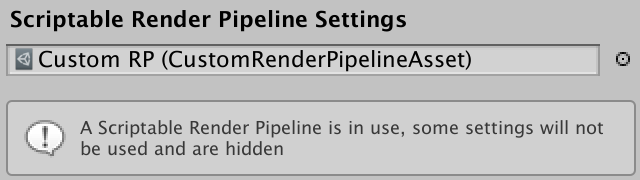
Replacing the default RP changed a few things. First, a lot of options have disappeared from the graphics settings, which is mentioned in an info panel. Second, we've disabled the default RP without providing a valid replacement, so nothing gets rendered anymore. The game window, scene window, and material previews are no longer functional. If you open the frame debugger—via Window / Analysis / Frame Debugger—and enable it, you will see that indeed nothing gets drawn in the game window.
Render Pipeline Instance
Create a CustomRenderPipeline class and put its script file in the same folder as CustomRenderPipelineAsset. This will be the type used for the RP instance that our asset returns, thus it must extend RenderPipeline.
using UnityEngine;
using UnityEngine.Rendering;

public class CustomRenderPipeline : RenderPipeline {}
RenderPipeline defines a protected abstract Render method that we have to override to create a concrete pipeline. It has two parameters: a ScriptableRenderContext and a Camera array. Leave the method empty.
	protected override void Render (
		ScriptableRenderContext context, Camera[] cameras
	) {}
This method was the entry point defined for custom SRPs, but because the camera array parameter requires allocating memory every frame an alternative has been introduced that has a list parameter instead. We can use that one in Unity 2022, but still have to keep the other version as well because it is declared abstract, even though it won't be used. Note that later profiler screenshots include the old allocations for the camera array.
	protected override void Render (
		ScriptableRenderContext context, List<Camera> cameras
	) { }
Make CustomRenderPipelineAsset.CreatePipeline return a new instance of CustomRenderPipeline. That will get us a valid and functional pipeline, although it doesn't render anything yet.
	protected override RenderPipeline CreatePipeline () {
		return new CustomRenderPipeline();
	}
Rendering
Each frame Unity invokes Render on the RP instance. It passes along a context struct that provides a connection to the native engine, which we can use for rendering. It also passes an array of cameras, as there can be multiple active cameras in the scene. It is the RP's responsibility to render all those cameras in the order that they are provided.
Camera Renderer
Each camera gets rendered independently. So rather than have CustomRenderPipeline render all camera's we'll forward that responsibility to a new class dedicated to rendering one camera. Name it CameraRenderer and give it a public Render method with a context and a camera parameter. Let's store these parameters in fields for convenience.
using UnityEngine;
using UnityEngine.Rendering;

public class CameraRenderer {

	ScriptableRenderContext context;

	Camera camera;

	public void Render (ScriptableRenderContext context, Camera camera) {
		this.context = context;
		this.camera = camera;
	}
}
Have CustomRenderPipeline create an instance of the renderer when it gets created, then use it to render all cameras in a loop.
	CameraRenderer renderer = new CameraRenderer();

	protected override void Render (
		ScriptableRenderContext context, Camera[] cameras
	) {}

	protected override void Render (
		ScriptableRenderContext context, List<Camera> cameras
	) {
		for (int i = 0; i < cameras.Count; i++) {
			renderer.Render(context, cameras[i]);
		}
	}
Our camera renderer is roughly equivalent to the scriptable renderers of the Universal RP. This approach will make it simple to support different rendering approaches per camera in the future, for example one for the first-person view and one for a 3D map overlay, or forward vs. deferred rendering. But for now we'll render all cameras the same way.
Drawing the Skybox
The job of CameraRenderer.Render is to draw all geometry that its camera can see. Isolate that specific task in a separate DrawVisibleGeometry method for clarity. We'll begin by having it draw the default the skybox, which can be done by invoking DrawSkybox on the context with the camera as an argument.
	public void Render (ScriptableRenderContext context, Camera camera) {
		this.context = context;
		this.camera = camera;

		DrawVisibleGeometry();
	}

	void DrawVisibleGeometry () {
		context.DrawSkybox(camera);
	}
This does not yet make the skybox appear. That's because the commands that we issue to the context are buffered. We have to submit the queued work for execution, by invoking Submit on the context. Let's do this in a separate Submit method, invoked after DrawVisibleGeometry.
	public void Render (ScriptableRenderContext context, Camera camera) {
		this.context = context;
		this.camera = camera;

		DrawVisibleGeometry();
		Submit();
	}

	void Submit () {
		context.Submit();
	}
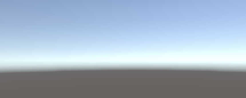
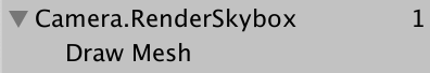
The skybox finally appears in both the game and scene window. You can also see an entry for it in the frame debugger when you enable it. It's listed as Camera.RenderSkybox, which has a single Draw Mesh item under it, which represents the actual draw call. This corresponds to the rendering of the game window. The frame debugger doesn't report drawing in other windows.
Note that the orientation of the camera currently doesn't affect how the skybox gets rendered. We pass the camera to DrawSkybox, but that's only used to determine whether the skybox should be drawn at all, which is controlled via the camera's clear flags.
To correctly render the skybox—and the entire scene—we have to set up the view-projection matrix. This transformation matrix combines the camera's position and orientation—the view matrix—with the camera's perspective or orthographic projection—the projection matrix. It is known in shaders as unity_MatrixVP, one of the shader properties used when geometry gets drawn. You can inspect this matrix in the frame debugger's ShaderProperties section when a draw call is selected.
At the moment, the unity_MatrixVP matrix is always the same. We have to apply the camera's properties to the context, via the SetupCameraProperties method. That sets up the matrix as well as some other properties. Do this before invoking DrawVisibleGeometry, in a separate Setup method.
	public void Render (ScriptableRenderContext context, Camera camera) {
		this.context = context;
		this.camera = camera;

		Setup();
		DrawVisibleGeometry();
		Submit();
	}

	void Setup () {
		context.SetupCameraProperties(camera);
	}

Command Buffers
The context delays the actual rendering until we submit it. Before that, we configure it and add commands to it for later execution. Some tasks—like drawing the skybox—can be issued via a dedicated method, but other commands have to be issued indirectly, via a separate command buffer. We need such a buffer to draw the other geometry in the scene.
To get a buffer we have to create a new CommandBuffer object instance. We need only one buffer, so create one by default for CameraRenderer and store a reference to it in a field. Also give the buffer a name so we can recognize it in the frame debugger. Render Camera will do.
	const string bufferName = "Render Camera";

	CommandBuffer buffer = new CommandBuffer {
		name = bufferName
	};
We can use command buffers to inject profiler samples, which will show up both in the profiler and the frame debugger. This is done by invoking BeginSample and EndSample at the appropriate points, which is at the beginning of Setup and Submit in our case. Both methods must be provided with the same sample name, for which we'll use the buffer's name.
	void Setup () {
		buffer.BeginSample(bufferName);
		context.SetupCameraProperties(camera);
	}

	void Submit () {
		buffer.EndSample(bufferName);
		context.Submit();
	}
To execute the buffer, invoke ExecuteCommandBuffer on the context with the buffer as an argument. That copies the commands from the buffer but doesn't clear it, we have to do that explicitly afterwards if we want to reuse it. Because execution and clearing is always done together it's handy to add a method that does both.
	void Setup () {
		buffer.BeginSample(bufferName);
		ExecuteBuffer();
		context.SetupCameraProperties(camera);
	}

	void Submit () {
		buffer.EndSample(bufferName);
		ExecuteBuffer();
		context.Submit();
	}

	void ExecuteBuffer () {
		context.ExecuteCommandBuffer(buffer);
		buffer.Clear();
	}
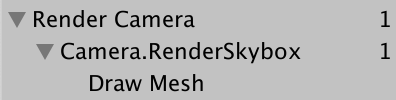
The Camera.RenderSkyBox sample now gets nested inside Render Camera.
Clearing the Render Target
Whatever we draw ends up getting rendered to the camera's render target, which is the frame buffer by default but could also be a render texture. Whatever was drawn to that target earlier is still there, which could interfere with the image that we are rendering now. To guarantee proper rendering we have to clear the render target to get rid of its old contents. That's done by invoking ClearRenderTarget on the command buffer, which belongs in the Setup method.
CommandBuffer.ClearRenderTarget requires at least three arguments. The first two indicate whether the depth and color data should be cleared, which is true for both. The third argument is the color used to clearing, for which we'll use Color.clear.
	void Setup () {
		buffer.BeginSample(bufferName);
		buffer.ClearRenderTarget(true, true, Color.clear);
		ExecuteBuffer();
		context.SetupCameraProperties(camera);
	}
The frame debugger now shows a Draw GL entry for the clear action, which shows up nested in an additional level of Render Camera. That happens because ClearRenderTarget wraps the clearing in a sample with the command buffer's name. We can get rid of the redundant nesting by clearing before beginning our own sample. That results in two adjacent Render Camera sample scopes, which get merged.
	void Setup () {
		buffer.ClearRenderTarget(true, true, Color.clear);
		buffer.BeginSample(bufferName);
		//buffer.ClearRenderTarget(true, true, Color.clear);
		ExecuteBuffer();
		context.SetupCameraProperties(camera);
	}
The Draw GL entry represent drawing a full-screen quad with the Hidden/InternalClear shader that writes to the render target, which isn't the most efficient way to clear it. This approach is used because we're clearing before setting up the camera properties. If we swap the order of those two steps we get the quick way to clear.
	void Setup () {
		context.SetupCameraProperties(camera);
		buffer.ClearRenderTarget(true, true, Color.clear);
		buffer.BeginSample(bufferName);
		ExecuteBuffer();
		//context.SetupCameraProperties(camera);
	}
Now we see Clear (color+Z+stencil), which indicates that both the color and depth buffers get cleared. Z represents the depth buffer and the stencil data is part the same buffer.
Culling
We're currently seeing the skybox, but not any of the objects that we put in the scene. Rather than drawing every object, we're only going to render those that are visible to the camera. We do that by starting with all objects with renderer components in the scene and then culling those that fall outside of the view frustum of the camera.
Figuring out what can be culled requires us to keep track of multiple camera settings and matrices, for which we can use the ScriptableCullingParameters struct. Instead of filling it ourselves, we can invoke TryGetCullingParameters on the camera. It returns whether the parameters could be successfully retrieved, as it might fail for degenerate camera settings. To get hold of the parameter data we have to supply it as an output argument, by writing out in front of it. Do this in a separate Cull method that returns either success or failure.
	bool Cull () {
		ScriptableCullingParameters p
		if (camera.TryGetCullingParameters(out p)) {
			return true;
		}
		return false;
	}
It is possible to inline the variable declaration inside the argument list when used as an output argument, so let's do that.
	bool Cull () {
		//ScriptableCullingParameters p
		if (camera.TryGetCullingParameters(out ScriptableCullingParameters p)) {
			return true;
		}
		return false;
	}
Invoke Cull before Setup in Render and abort if it failed.
	public void Render (ScriptableRenderContext context, Camera camera) {
		this.context = context;
		this.camera = camera;

		if (!Cull()) {
			return;
		}

		Setup();
		DrawVisibleGeometry();
		Submit();
	}
Actual culling is done by invoking Cull on the context, which produces a CullingResults struct. Do this in Cull if successful and store the results in a field. In this case we have to pass the culling parameters as a reference argument, by writing ref in front of it.
	CullingResults cullingResults;

	…

	bool Cull () {
		if (camera.TryGetCullingParameters(out ScriptableCullingParameters p)) {
			cullingResults = context.Cull(ref p);
			return true;
		}
		return false;
	}
Drawing Geometry
Once we know what is visible we can move on to rendering those things. That is done by invoking DrawRenderers on the context with the culling results as an argument, telling it which renderers to use. Besides that, we have to supply drawing settings and filtering settings. Both are structs—DrawingSettings and FilteringSettings—for which we'll initially use their default constructors. Both have to be passed by reference. Do this in DrawVisibleGeometry, before drawing the skybox.
	void DrawVisibleGeometry () {
		var drawingSettings = new DrawingSettings();
		var filteringSettings = new FilteringSettings();

		context.DrawRenderers(
			cullingResults, ref drawingSettings, ref filteringSettings
		);

		context.DrawSkybox(camera);
	}
We don't see anything yet because we also have to indicate which kind of shader passes are allowed. As we only support unlit shaders in this tutorial we have to fetch the shader tag ID for the SRPDefaultUnlit pass, which we can do once and cache it in a static field.
static ShaderTagId unlitShaderTagId = new ShaderTagId("SRPDefaultUnlit");
Provide it as the first argument of the DrawingSettings constructor, along with a new SortingSettings struct value. Pass the camera to the constructor of the sorting settings, as it's used to determine whether orthographic or distance-based sorting applies.
	void DrawVisibleGeometry () {
		var sortingSettings = new SortingSettings(camera);
		var drawingSettings = new DrawingSettings(
			unlitShaderTagId, sortingSettings
		);
		…
	}
Besides that we also have to indicate which render queues are allowed. Pass RenderQueueRange.all to the FilteringSettings constructor so we include everything.
var filteringSettings = new FilteringSettings(RenderQueueRange.all);
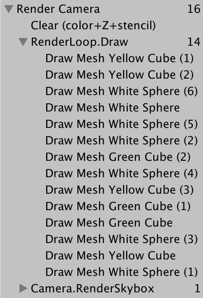
Only the visible objects that use the unlit shader get drawn. All the draw calls are listed in the frame debugger, grouped under RenderLoop.Draw. There's something weird going on with transparent objects, but let's first look at the order in which the objects are drawn. That's shown by the frame debugger and you can step through the draw calls by selecting one after the other or using the arrow keys.
The drawing order is haphazard. We can force a specific draw order by setting the criteria property of the sorting settings. Let's use SortingCriteria.CommonOpaque.
		var sortingSettings = new SortingSettings(camera) {
			criteria = SortingCriteria.CommonOpaque
		};
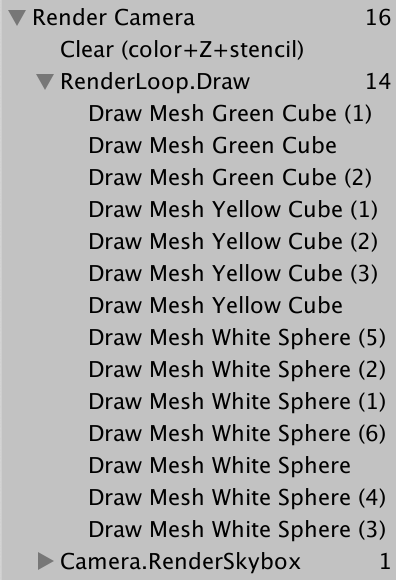
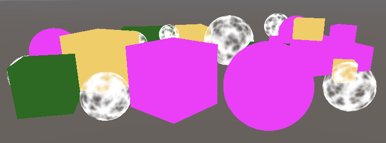
Objects now get more-or-less drawn front-to-back, which is ideal for opaque objects. If something ends up drawn behind something else its hidden fragments can be skipped, which speeds up rendering. The common opaque sorting option also takes some other criteria into consideration, including the render queue and materials.
Drawing Opaque and Transparent Geometry Separately
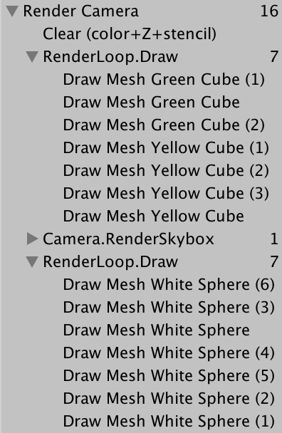
The frame debugger shows us that transparent objects get drawn, but the skybox gets drawn over everything that doesn't end up in front of an opaque object. The skybox gets drawn after the opaque geometry so all its hidden fragments can get skipped, but it overwrites transparent geometry. That happens because transparent shaders do not write to the depth buffer. They don't hide whatever's behind them, because we can see through them. The solution is to first drawn opaque objects, then the skybox, and only then transparent objects.
We can eliminate the transparent objects from the initial DrawRenderers invocation by switching to RenderQueueRange.opaque.
var filteringSettings = new FilteringSettings(RenderQueueRange.opaque);
Then after drawing the skybox invoke DrawRenderers again. But before doing so change the render queue range to RenderQueueRange.transparent. Also change the sorting criteria to SortingCriteria.CommonTransparent and again set the sorting of the drawing settings. That reverses the draw order of the transparent objects.
		context.DrawSkybox(camera);

		sortingSettings.criteria = SortingCriteria.CommonTransparent;
		drawingSettings.sortingSettings = sortingSettings;
		filteringSettings.renderQueueRange = RenderQueueRange.transparent;

		context.DrawRenderers(
			cullingResults, ref drawingSettings, ref filteringSettings
		);
Editor Rendering
Our RP correctly draws unlit objects, but there are a few things that we can do to improve the experience of working with it in the Unity editor.
Drawing Legacy Shaders
Because our pipeline only supports unlit shaders passes, objects that use different passes are not rendered, making them invisible. While this is correct, it hides the fact that some objects in the scene use the wrong shader. So let's render them anyway, but separately.
If someone were to start with a default Unity project and later switch to our RP then they might have objects with the wrong shader in their scenes. To cover all Unity's default shaders we have to use shaders tag IDs for the Always, ForwardBase, PrepassBase, Vertex, VertexLMRGBM, and VertexLM passes. Keep track of these in a static array.
	static ShaderTagId[] legacyShaderTagIds = {
		new ShaderTagId("Always"),
		new ShaderTagId("ForwardBase"),
		new ShaderTagId("PrepassBase"),
		new ShaderTagId("Vertex"),
		new ShaderTagId("VertexLMRGBM"),
		new ShaderTagId("VertexLM")
	};
Draw all unsupported shaders in a separate method after the visible geometry, starting with just the first pass. As these are invalid passes the results will be wrong anyway so we don't care about the other settings. We can get default filtering settings via the FilteringSettings.defaultValue property.
	public void Render (ScriptableRenderContext context, Camera camera) {
		…

		Setup();
		DrawVisibleGeometry();
		DrawUnsupportedShaders();
		Submit();
	}

	…

	void DrawUnsupportedShaders () {
		var drawingSettings = new DrawingSettings(
			legacyShaderTagIds[0], new SortingSettings(camera)
		);
		var filteringSettings = FilteringSettings.defaultValue;
		context.DrawRenderers(
			cullingResults, ref drawingSettings, ref filteringSettings
		);
	}
We can draw multiple passes by invoking SetShaderPassName on the drawing settings with a draw order index and tag as arguments. Do this for all passes in the array, starting at the second as we already set the first pass when constructing the drawing settings.
		var drawingSettings = new DrawingSettings(
			legacyShaderTagIds[0], new SortingSettings(camera)
		);
		for (int i = 1; i < legacyShaderTagIds.Length; i++) {
			drawingSettings.SetShaderPassName(i, legacyShaderTagIds[i]);
		}
Objects rendered with the standard shader show up, but they're now solid black because our RP hasn't set up the required shader properties for them.
Error Material
To clearly indicate which objects use unsupported shaders we'll draw them with Unity's error shader. Construct a new material with that shader as an argument, which we can find by invoking Shader.Find with the Hidden/InternalErrorShader string as an argument. Cache the material via a static field so we won't create a new one each frame. Then assign it to the overrideMaterial property of the drawing settings.
	static Material errorMaterial;

	…

	void DrawUnsupportedShaders () {
		if (errorMaterial == null) {
			errorMaterial =
				new Material(Shader.Find("Hidden/InternalErrorShader"));
		}
		var drawingSettings = new DrawingSettings(
			legacyShaderTagIds[0], new SortingSettings(camera)
		) {
			overrideMaterial = errorMaterial
		};
		…
	}
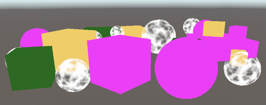
Now all invalid objects are visible and obviously wrong.
Partial Class
Drawing invalid objects is useful for development but is not meant for released apps. So let's put all editor-only code for CameraRenderer in a separate partial class file. Begin by duplicating the original CameraRenderer script asset and renaming it to CameraRenderer.Editor.
Then turn the original CameraRenderer into a partial class and remove the tag array, error material, and DrawUnsupportedShaders method from it.
public partial class CameraRenderer { … }
Clean the other partial class file so it only contains what we removed from the other.
using UnityEngine;
using UnityEngine.Rendering;

partial class CameraRenderer {

	static ShaderTagId[] legacyShaderTagIds = {	… };

	static Material errorMaterial;

	void DrawUnsupportedShaders () { … }
}
The content of the editor part only needs to exist in the editor, so make it conditional on UNITY_EDITOR.
partial class CameraRenderer {

#if UNITY_EDITOR

	static ShaderTagId[] legacyShaderTagIds = { … }
	};

	static Material errorMaterial;

	void DrawUnsupportedShaders () { … }

#endif
}
However, making a build will fail at this point, because the other part always contains the invocation of DrawUnsupportedShaders, which now only exists while in the editor. To solve this we make that method partial as well. We do that by always declaring the method signature with partial in front of it, similar to an abstract method declaration. We can do that in any part of the class definition, so let's put it in the editor part. The full method declaration must be marked with partial as well.
	partial void DrawUnsupportedShaders ();

#if UNITY_EDITOR

	…

	partial void DrawUnsupportedShaders () { … }

#endif
Compilation for a build now succeeds. The compiler will strip out the invocation of all partial methods that didn't end up with a full declaration.
Drawing Gizmos
Currently our RP doesn't draw gizmos, neither in the scene window nor in the game window if they are enabled there.
We can check whether gizmos should be drawn by invoking UnityEditor.Handles.ShouldRenderGizmos. If so, we have to invoke DrawGizmos on the context with the camera as an argument, plus a second argument to indicate which gizmo subset should be drawn. There are two subsets, for before and after image effects. As we don't support image effects at this point we'll invoke both. Do this in a new editor-only DrawGizmos method.
using UnityEditor;
using UnityEngine;
using UnityEngine.Rendering;

partial class CameraRenderer {

	partial void DrawGizmos ();

	partial void DrawUnsupportedShaders ();

#if UNITY_EDITOR

	…

	partial void DrawGizmos () {
		if (Handles.ShouldRenderGizmos()) {
			context.DrawGizmos(camera, GizmoSubset.PreImageEffects);
			context.DrawGizmos(camera, GizmoSubset.PostImageEffects);
		}
	}

	partial void DrawUnsupportedShaders () { … }

#endif
}
The gizmos should be drawn after everything else.
	public void Render (ScriptableRenderContext context, Camera camera) {
		…

		Setup();
		DrawVisibleGeometry();
		DrawUnsupportedShaders();
		DrawGizmos();
		Submit();
	}
Drawing Unity UI
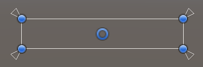
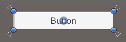
Another thing that requires our attention is Unity's in-game user interface. For example, create a simple UI by adding a button via GameObject / UI / Button. It will show up in the game window, but not the scene window.
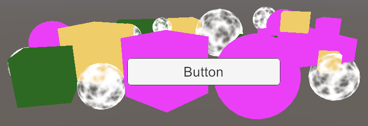
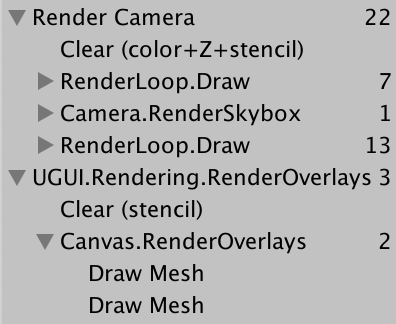
The frame debugger shows us that the UI is rendered separately, not by our RP.
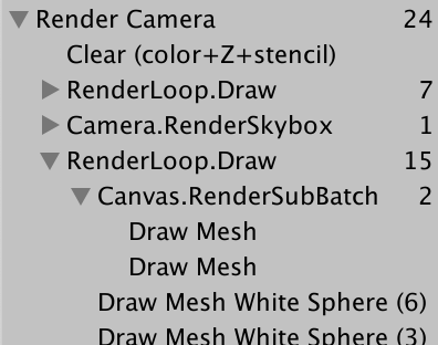
At least, that's the case when the Render Mode of the canvas component is set to Screen Space - Overlay, which is the default. Changing it to Screen Space - Camera and using the main camera as its Render Camera will make it part of the transparent geometry.
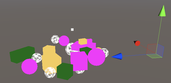
The UI always uses the World Space mode when it gets rendered in the scene window, which is why it usually ends up very large. But while we can edit the UI via the scene window it doesn't get drawn.
We have to explicitly add the UI to the world geometry when rendering for the scene window, by invoking ScriptableRenderContext.EmitWorldGeometryForSceneView with the camera as an argument. Do this in a new editor-only PrepareForSceneWindow method. We're rendering with the scene camera when its cameraType property is equal to CameraType.SceneView.
	partial void PrepareForSceneWindow ();

#if UNITY_EDITOR

	…

	partial void PrepareForSceneWindow () {
		if (camera.cameraType == CameraType.SceneView) {
			ScriptableRenderContext.EmitWorldGeometryForSceneView(camera);
		}
	}
As that might add geometry to the scene it has to be done before culling.
		PrepareForSceneWindow();
		if (!Cull()) {
			return;
		}
Multiple Cameras
It is possible to have more that one active camera in the scene. If so, we have to make sure that they work together.
Two Cameras
Each camera has a Depth value, which is −1 for the default main camera. They get rendered in increasing order of depth. To see this, duplicate the Main Camera, rename it to Secondary Camera, and set its Depth to 0. It's also a good idea to give it another tag, as MainCamera is supposed to be used by only a single camera.
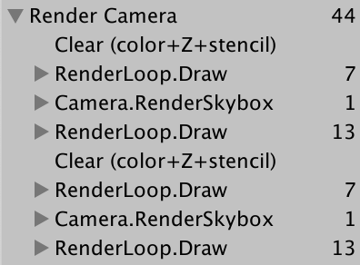
The scene now gets rendered twice. The resulting image is still the same because the render target gets cleared in between. The frame debugger shows this, but because adjacent sample scopes with the same name get merged we end up with a single Render Camera scope.
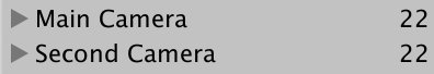
It's clearer if each camera gets its own scope. To make that possible, add an editor-only PrepareBuffer method that makes the buffer's name equal to the camera's.
	partial void PrepareBuffer ();

#if UNITY_EDITOR

	…

	partial void PrepareBuffer () {
		buffer.name = camera.name;
	}

#endif
Invoke it before we prepare the scene window.
		PrepareBuffer();
		PrepareForSceneWindow();
Dealing with Changing Buffer Names
Although the frame debugger now shows a separate sample hierarchy per camera, when we enter play mode Unity's console will get filled with messages warning us that BeginSample and EndSample counts must match. It gets confused because we're using different names for the samples and their buffer. Besides that, we also end up allocating memory each time we access the camera's name property, so we don't want to do that in builds.
To tackle both issues we'll add a SampleName string property. If we're in the editor we set it in PrepareBuffer along with the buffer's name, otherwise it's simply a constant alias for the Render Camera string.
#if UNITY_EDITOR

	…

	string SampleName { get; set; }

	…

	partial void PrepareBuffer () {
		buffer.name = SampleName = camera.name;
	}

#else

	const string SampleName = bufferName;

#endif
Use SampleName for the sample in Setup and Submit.
	void Setup () {
		context.SetupCameraProperties(camera);
		buffer.ClearRenderTarget(true, true, Color.clear);
		buffer.BeginSample(SampleName);
		ExecuteBuffer();
	}

	void Submit () {
		buffer.EndSample(SampleName);
		ExecuteBuffer();
		context.Submit();
	}
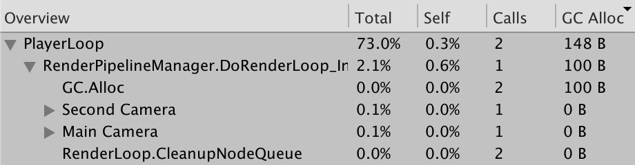
We can see the difference by checking the profiler—opened via Window / Analysis / Profiler—and playing in the editor first. Switch to Hierarchy mode and sort by the GC Alloc column. You'll see an entry for two invocations of GC.Alloc, allocating 100 bytes in total, which is causes by the retrieval of the camera names. Further down you'll see those names show up as samples: Main Camera and Secondary Camera.
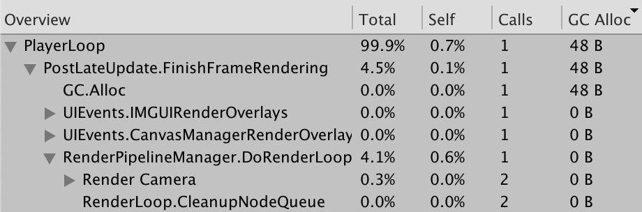
Next, make a build with Development Build and Autoconnect Profiler enabled. Play the build and make sure that the profiler is connected and recording. In this case we don't get the 100 bytes of allocation and we get the single Render Camera sample instead.
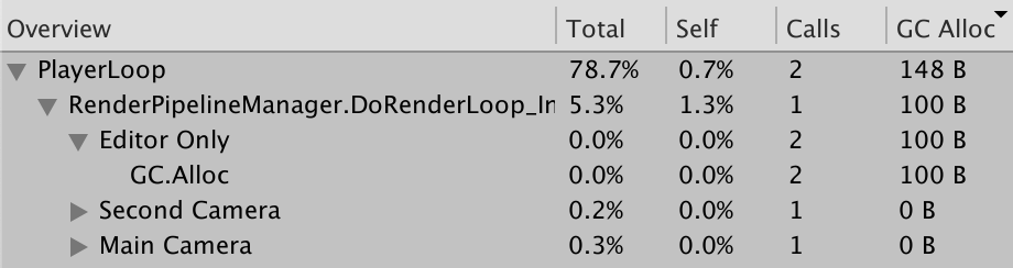
We can make it clear that we're allocating memory only in the editor and not in builds by wrapping the camera name retrieval in a profiler sample named Editor Only. In this case we need to invoke Profiler.BeginSample and Profiler.EndSample from the UnityEngine.Profiling namespace. Only BeginSample needs to be passed the name.
using UnityEditor;
using UnityEngine;
using UnityEngine.Profiling;
using UnityEngine.Rendering;

partial class CameraRenderer {

	…

#if UNITY_EDITOR

	…

	partial void PrepareBuffer () {
		Profiler.BeginSample("Editor Only");
		buffer.name = SampleName = camera.name;
		Profiler.EndSample();
	}

#else

	string SampleName => bufferName;

#endif
}
Layers
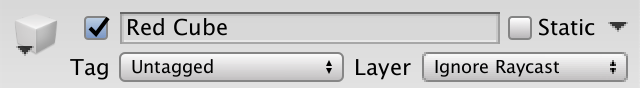
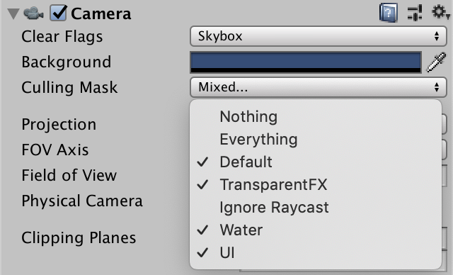
Cameras can also be configured to only see things on certain layers. This is done by adjusting their Culling Mask. To see this in action let's move all objects that use the standard shader to the Ignore Raycast layer.
Exclude that layer from the culling mask of Main Camera.
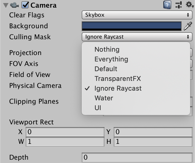
And make it the only layer seen by Secondary Camera.
Because Secondary Camera renders last we end up seeing only the invalid objects.
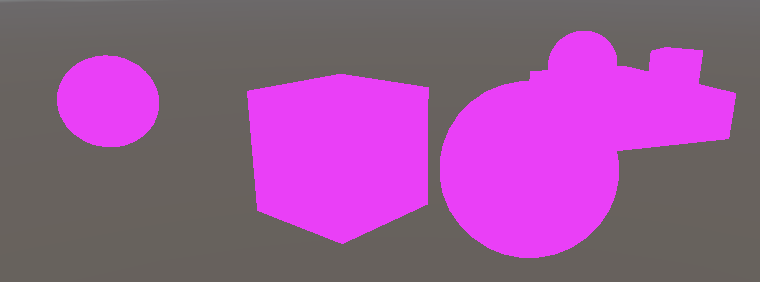
Clear Flags
We can combine the results of both cameras by adjusting the clear flags of the second one that gets rendered. They're defined by a CameraClearFlags enum which we can retrieve via the camera's clearFlags property. Do this in Setup before clearing.
	void Setup () {
		context.SetupCameraProperties(camera);
		CameraClearFlags flags = camera.clearFlags;
		buffer.ClearRenderTarget(true, true, Color.clear);
		buffer.BeginSample(SampleName);
		ExecuteBuffer();
	}
The CameraClearFlags enum defines four values. From 1 to 4 they are Skybox, Color€, Depth, and Nothing. These aren't actually independent flag values but represent a decreasing amount of clearing. The depth buffer has to be cleared in all cases except the last one, so when the flags value is at most Depth.
		buffer.ClearRenderTarget(
			flags <= CameraClearFlags.Depth, true, Color.clear
		);
We should only really need to clear the color buffer when flags are set to Color€, because in the case of Skybox we end up replacing all previous color data anyway. However,
		buffer.ClearRenderTarget(
			flags <= CameraClearFlags.Depth,
			flags == CameraClearFlags.Color€,
			Color.clear
		);
For Unity 2022 I changed this to always clear the color unless explicitly told not to, because the render target could contain not-a-number and infinity values which can create blending artifacts. Also, the frame debugger could show random data which makes debugging difficult.
flags <= CameraClearFlags.Color€
And if we're clearing to a solid color we have to use the camera's background color. But because we're rendering in linear color space we have to convert that color to linear space, so we end up needing camera.backgroundColor.linear. In all other cases the color doesn't matter, so we can suffice with Color.clear.
		buffer.ClearRenderTarget(
			flags <= CameraClearFlags.Depth,
			flags == CameraClearFlags.Color€,
			flags == CameraClearFlags.Color€ ?
				camera.backgroundColor.linear : Color.clear
		);
Because Main Camera is the first to render, its Clear Flags should be set to either Skybox or Color€. When the frame debugger is enabled we always begin with a clear buffer, but this is not guaranteed in general.
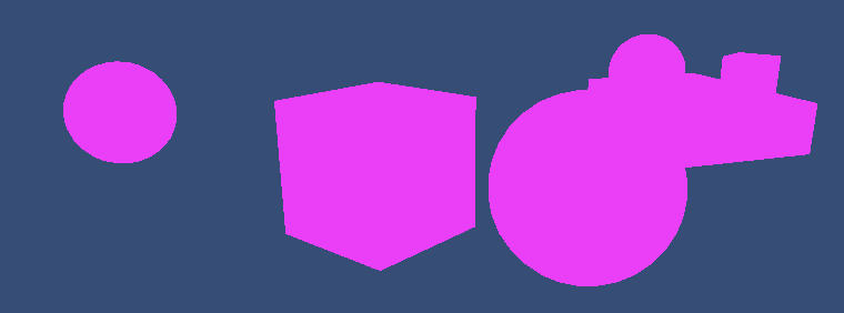
The clear flags of Secondary Camera determines how the rendering of both cameras gets combined. In the case of skybox or color the previous results get completely replaced. When only depth is cleared Secondary Camera renders as normal except that it doesn't draw a skybox, so the previous results show up as the background. When nothing gets cleared the depth buffer is retained, so unlit objects end up occluding invalid objects as if they were drawn by the same camera. However, transparent objects drawn by the previous camera have no depth information, so are drawn over, just like the skybox did earlier.
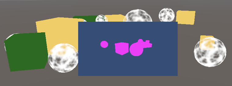
By adjusting the camera's Viewport Rect it is also possible to reduce the rendered area to only a fraction of the entire render target. The rest of the render target remains unaffected. In this case clearing happens with the Hidden/InternalClear shader. The stencil buffer is used to limit rendering to the viewport area.
Note that rendering more than one camera per frame means culling, setup, sorting, etc. has to be done multiple times as well. Using one camera per unique point of view is typically the most efficient approach.
The next tutorial is Draw Calls.