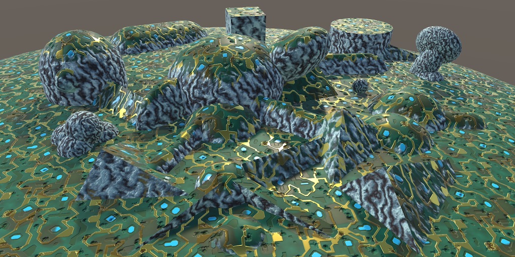
Triplanar Mapping
Texturing Arbitrary Surfaces
- Remove dependency on UV and tangents.
- Support a generic surface approach.
- Use planar projections.
- Blend between three mappings.
This tutorial is about supporting triplanar texture mapping. It uses the FXAA tutorial project as its foundation.
This tutorial is made with Unity 2017.4.1f1.
Texturing Without UV Coordinates
The usual way to perform texture mapping is by using the UV coordinates stored per-vertex in a mesh. But this is not the only way to do it. Sometimes, there are no UV coordinates available. For example, when working with procedural geometry of arbitrary shapes. When creating a terrain or cave systems at run-time, it usually isn't feasible to generate UV coordinates for an appropriate texture unwrap. In those cases, we have to use an alternative way to map textures onto our surfaces. One such way is triplanar mapping.
Up to this point, we've always assumed that UV coordinates are available. Our My Lighting Input and My Lighting shader include files depend on them. While we could create alternatives that do not depend on vertex UV, it would be more convenient if our current files could be made to work both with and without UV. This requires a few changes.
We keep the current approach as the default, but will switch to working without UV when NO_DEFAULT_UV is defined.
Doing Without Default UV
When the mesh data doesn't contain UV, then we don't have any UV to pass from the vertex to the fragment program. So make the existence of the UV interpolator in My Lighting Input dependent on NO_DEFAULT_UV.
struct InterpolatorsVertex {
	…

	#if !defined(NO_DEFAULT_UV)
		float4 uv : TEXCOORD0;
	#endif

	…
};

struct Interpolators {
	…

	#if !defined(NO_DEFAULT_UV)
		float4 uv : TEXCOORD0;
	#endif

	…
};
There are multiple functions that assume the interpolators always contain UV, so we have to make sure that they keep working and compiling. We'll do that by introducing a new GetDefaultUV function below the interpolator declarations. When no UV are available, it will simply return zeros, otherwise the regular UV.
We'll also make it possible to provide an alternative approach by defining UV_FUNCTION, in case that might be useful. This works like ALBEDO_FUNCTION, except that an override has to be defined before the inclusion of My Lighting Input.
float4 GetDefaultUV (Interpolators i) {
	#if defined(NO_DEFAULT_UV)
		return float4(0, 0, 0, 0);
	#else
		return i.uv;
	#endif
}

#if !defined(UV_FUNCTION)
	#define UV_FUNCTION GetDefaultUV
#endif
Now we can change all usage of i.uv with UV_FUNCTION(i). I've only shown the change for GetDetailMask, but it applies to all getter functions.
float GetDetailMask (Interpolators i) {
	#if defined (_DETAIL_MASK)
		return tex2D(_DetailMask, UV_FUNCTION(i).xy).a;
	#else
		return 1;
	#endif
}
Moving on to My Lighting, we must make sure that all UV-related work in the vertex program is skipped when no UV are available. This applies to the texture coordinate transformation, and also the default vertex displacement approach.
InterpolatorsVertex MyVertexProgram (VertexData v) {
	…

	#if !defined(NO_DEFAULT_UV)
		i.uv.xy = TRANSFORM_TEX(v.uv, _MainTex);
		i.uv.zw = TRANSFORM_TEX(v.uv, _DetailTex);

		#if VERTEX_DISPLACEMENT
			float displacement = tex2Dlod(_DisplacementMap, float4(i.uv.xy, 0, 0)).g;
			displacement = (displacement - 0.5) * _DisplacementStrength;
			v.normal = normalize(v.normal);
			v.vertex.xyz += v.normal * displacement;
		#endif
	#endif

	…
}
The parallax effect also relies on default UV, so skip it when UV are not available.
void ApplyParallax (inout Interpolators i) {
	#if defined(_PARALLAX_MAP) && !defined(NO_DEFAULT_UV)
		…
	#endif
}
Collecting Surface Properties
Without UV, there must be another way to determine the surface properties used for lighting. To make this as generic as possible, our include files shouldn't care how these properties are obtained. All we need is a universal way to provide surface properties. We can use an approach akin to Unity's surface shaders, relying on a function to set all surface properties.
Create a new MySurface.cginc include file. In it, define a SurfaceData struct that contains all surface properties needed for lighting. That's albedo, emission, normal, alpha, metallic, occlusion, and smoothness.
#if !defined(MY_SURFACE_INCLUDED)
#define MY_SURFACE_INCLUDED

struct SurfaceData {
	float3 albedo, emission, normal;
	float alpha, metallic, occlusion, smoothness;
};

#endif
We put it in a separate file, so other code can use it before including any other files. But our files will rely on it as well, so include it in My Lighting Input.
#include "UnityPBSLighting.cginc"
#include "AutoLight.cginc"
#include "MySurface.cginc"
In My Lighting, setup a new SurfaceData surface variable with the default functions, at the beginning of MyFragmentProgram, after ApplyParallax and before alpha is used. Then change the alpha code to rely on surface.alpha instead of invoking GetAlpha. Also move InitializeFragmentNormal so the normal vector is handled before the surface is configured.
FragmentOutput MyFragmentProgram (Interpolators i) {
	UNITY_SETUP_INSTANCE_ID(i);
	#if defined(LOD_FADE_CROSSFADE)
		UnityApplyDitherCrossFade(i.vpos);
	#endif

	ApplyParallax(i);

	InitializeFragmentNormal(i);

	SurfaceData surface;
	surface.normal = i.normal;
	surface.albedo = ALBEDO_FUNCTION(i);
	surface.alpha = GetAlpha(i);
	surface.emission = GetEmission(i);
	surface.metallic = GetMetallic(i);
	surface.occlusion = GetOcclusion(i);
	surface.smoothness = GetSmoothness(i);

	float alpha = surface.alpha;
	#if defined(_RENDERING_CUTOUT)
		clip(alpha - _Cutoff);
	#endif

//	InitializeFragmentNormal(i);

	…
}
Now rely on surface instead of invoking the getter functions again when determining the fragment's color.
	float3 albedo = DiffuseAndSpecularFromMetallic(
		surface.albedo, surface.metallic, specularTint, oneMinusReflectivity
	);

	…

	float4 color = UNITY_BRDF_PBS(
		albedo, specularTint,
		oneMinusReflectivity, surface.smoothness,
		i.normal, viewDir,
		CreateLight(i), CreateIndirectLight(i, viewDir)
	);
	color.rgb += surface.emission;
And when filling the G-buffers for deferred rendering.
	#if defined(DEFERRED_PASS)
		#if !defined(UNITY_HDR_ON)
			color.rgb = exp2(-color.rgb);
		#endif
		output.gBuffer0.rgb = albedo;
		output.gBuffer0.a = surface.occlusion;
		output.gBuffer1.rgb = specularTint;
		output.gBuffer1.a = surface.smoothness;
		output.gBuffer2 = float4(i.normal * 0.5 + 0.5, 1);
		output.gBuffer3 = color;

		…
	#endif
The CreateIndirectLight function also used the getter functions, so add a SurfaceData parameter to it and use that instead.
UnityIndirect CreateIndirectLight (
	Interpolators i, float3 viewDir, SurfaceData surface
) {
	…

	#if defined(FORWARD_BASE_PASS) || defined(DEFERRED_PASS)
		…

		float3 reflectionDir = reflect(-viewDir, i.normal);
		Unity_GlossyEnvironmentData envData;
		envData.roughness = 1 - surface.smoothness;
		…

		float occlusion = surface.occlusion;
		…
	#endif

	return indirectLight;
}
Then add surface as an argument to its invocation in MyFragmentProgram.
CreateLight(i), CreateIndirectLight(i, viewDir, surface)
Customized Surfaces
To make it possible to change how the surface data is obtained, we'll again allow the definition of a custom function. This function needs input to work with. By default, that would be the UV coordinates, both the main and detail UV packed in a single float4. Alternative inputs could be a position and a normal vector. Add a SurfaceParameters struct to our Surface file that contains all these inputs.
struct SurfaceData {
	float3 albedo, emission, normal;
	float alpha, metallic, occlusion, smoothness;
};

struct SurfaceParameters {
	float3 normal, position;
	float4 uv;
};
Back in My Lighting, adjust MyFragmentProgram so it uses a different way to setup the surface data when a SURFACE_FUNCTION is defined. When this is the case, fill surface with the normal vector and set all other values to their default. Then create the surface parameters and invoke the custom surface function. Its arguments are the surface—as an inout parameter—and the parameters struct.
	SurfaceData surface;
	#if defined(SURFACE_FUNCTION)
		surface.normal = i.normal;
		surface.albedo = 1;
		surface.alpha = 1;
		surface.emission = 0;
		surface.metallic = 0;
		surface.occlusion = 1;
		surface.smoothness = 0.5;

		SurfaceParameters sp;
		sp.normal = i.normal;
		sp.position = i.worldPos.xyz;
		sp.uv = UV_FUNCTION(i);

		SURFACE_FUNCTION(surface, sp);
	#else
		surface.normal = i.normal;
		surface.albedo = ALBEDO_FUNCTION(i);
		surface.alpha = GetAlpha(i);
		surface.emission = GetEmission(i);
		surface.metallic = GetMetallic(i);
		surface.occlusion = GetOcclusion(i);
		surface.smoothness = GetSmoothness(i);
	#endif
As it might be possible that SURFACE_FUNCTION changes the surface normal, assign it back to i.normal afterwards. That way we don't need to change all the code that uses i.normal.
	SurfaceData surface;
	#if defined(SURFACE_FUNCTION)
		…
	#else
		…
	#endif
	i.normal = surface.normal;
No Tangent Space
Note that unlike Unity's surface shader approach, we're working with a normal vector in world space, not tangent space. If we want to use tangent-space normal mapping in SURFACE_FUNCTION, then we have to explicitly do this ourselves. We could also support more configuration options about how the normal should be treated both before and after invoking SURFACE_FUNCTION, but we won't do that in this tutorial.
What we will do is make it possible to turn off the default tangent-space normal mapping approach. This saves work when tangents aren't used. We'll do this by only turning on tangent space when the default normal mapping or parallax mapping is active. Indicate this in My Lighting Input with a convenient REQUIRES_TANGENT_SPACE macro.
#if defined(_NORMAL_MAP) || defined(_DETAIL_NORMAL_MAP) || defined(_PARALLAX_MAP)
	#define REQUIRES_TANGENT_SPACE 1
	#define TESSELLATION_TANGENT 1
#endif
#define TESSELLATION_UV1 1
#define TESSELLATION_UV2 1
Now we only have to include the tangent and binormal vector interpolators when needed.
struct InterpolatorsVertex {
	…

	#if REQUIRES_TANGENT_SPACE
		#if defined(BINORMAL_PER_FRAGMENT)
			float4 tangent : TEXCOORD2;
		#else
			float3 tangent : TEXCOORD2;
			float3 binormal : TEXCOORD3;
		#endif
	#endif

	…
};

struct Interpolators {
	…

	#if REQUIRES_TANGENT_SPACE
		#if defined(BINORMAL_PER_FRAGMENT)
			float4 tangent : TEXCOORD2;
		#else
			float3 tangent : TEXCOORD2;
			float3 binormal : TEXCOORD3;
		#endif
	#endif

	…
};
In My Lighting, we could skip setting up these vectors in MyVertexProgram.
InterpolatorsVertex MyVertexProgram (VertexData v) {
	…

	#if REQUIRES_TANGENT_SPACE
		#if defined(BINORMAL_PER_FRAGMENT)
			i.tangent = float4(UnityObjectToWorldDir(v.tangent.xyz), v.tangent.w);
		#else
			i.tangent = UnityObjectToWorldDir(v.tangent.xyz);
			i.binormal = CreateBinormal(i.normal, i.tangent, v.tangent.w);
		#endif
	#endif

	…
}
And without tangent space, InitializeFragmentNormal is reduced so simply normalizing the interpolated normal.
void InitializeFragmentNormal(inout Interpolators i) {
	#if REQUIRES_TANGENT_SPACE
		float3 tangentSpaceNormal = GetTangentSpaceNormal(i);
		#if defined(BINORMAL_PER_FRAGMENT)
			float3 binormal =
				CreateBinormal(i.normal, i.tangent.xyz, i.tangent.w);
		#else
			float3 binormal = i.binormal;
		#endif

		i.normal = normalize(
			tangentSpaceNormal.x * i.tangent +
			tangentSpaceNormal.y * binormal +
			tangentSpaceNormal.z * i.normal
		);
	#else
		i.normal = normalize(i.normal);
	#endif
}
Triplanar Shader
All our shaders still work, but it's now possible to use our include files without tangent space and with alternative surface data. Let's create a new shader to take advantage of this. First, create a new MyTriplanarMapping.cginc include file. Have it define NO_DEFAULT_UV, then include Surface.cginc. Actually, as we'll use the _MainTex property that's already defined in My Lighting Input, include that file instead. Then create a MyTriplanarSurfaceFunction with an inout SurfaceData parameter and a regular SurfaceParameters parameter. For now, just have it use the normal to set the albedo. Define this function as SURFACE_FUNCTION.
#if !defined(MY_TRIPLANAR_MAPPING_INCLUDED)
#define MY_TRIPLANAR_MAPPING_INCLUDED
#define NO_DEFAULT_UV
#include "My Lighting Input.cginc"
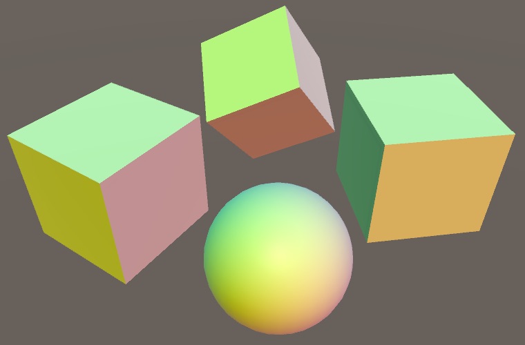
void MyTriPlanarSurfaceFunction (
inout SurfaceData surface, SurfaceParameters parameters
) {
surface.albedo = parameters.normal * 0.5 + 0.5;
}
#define SURFACE_FUNCTION MyTriPlanarSurfaceFunction
#endif
Create a new shader that uses this include file, instead of My Lighting Input. We'll make a minimal shader without transparency, supporting just the usual rendering pipelines, plus fog and instancing. Here is the shader with the forward base and additive passes.
Shader "Custom/Triplanar Mapping" {

	Properties {
		_MainTex ("Albedo", 2D) = "white" {}
	}

	SubShader {

		Pass {
			Tags {
				"LightMode" = "ForwardBase"
			}

			CGPROGRAM

			#pragma target 3.0

			#pragma multi_compile_fwdbase
			#pragma multi_compile_fog
			#pragma multi_compile_instancing

			#pragma vertex MyVertexProgram
			#pragma fragment MyFragmentProgram

			#define FORWARD_BASE_PASS

			#include "MyTriplanarMapping.cginc"
			#include "My Lighting.cginc"

			ENDCG
		}

		Pass {
			Tags {
				"LightMode" = "ForwardAdd"
			}

			Blend One One
			ZWrite Off

			CGPROGRAM

			#pragma target 3.0

			#pragma multi_compile_fwdadd_fullshadows
			#pragma multi_compile_fog

			#pragma vertex MyVertexProgram
			#pragma fragment MyFragmentProgram

			#include "MyTriplanarMapping.cginc"
			#include "My Lighting.cginc"

			ENDCG
		}
	}
}
And here are the deferred and shadow passes. Note that the shadow pass doesn't need special treatment, because it doesn't care about surface properties of opaque geometry. We don't add support for lightmapping yet, so no meta pass at this point.
Shader "Custom/Triplanar Mapping" {

	Properties {
		_MainTex ("Albedo", 2D) = "white" {}
	}

	SubShader {

		…

		Pass {
			Tags {
				"LightMode" = "Deferred"
			}

			CGPROGRAM

			#pragma target 3.0
			#pragma exclude_renderers nomrt

			#pragma multi_compile_prepassfinal
			#pragma multi_compile_instancing

			#pragma vertex MyVertexProgram
			#pragma fragment MyFragmentProgram

			#define DEFERRED_PASS

			#include "MyTriplanarMapping.cginc"
			#include "My Lighting.cginc"

			ENDCG
		}

		Pass {
			Tags {
				"LightMode" = "ShadowCaster"
			}

			CGPROGRAM

			#pragma target 3.0

			#pragma multi_compile_shadowcaster
			#pragma multi_compile_instancing

			#pragma vertex MyShadowVertexProgram
			#pragma fragment MyShadowFragmentProgram

			#include "My Shadows.cginc"

			ENDCG
		}
	}
}
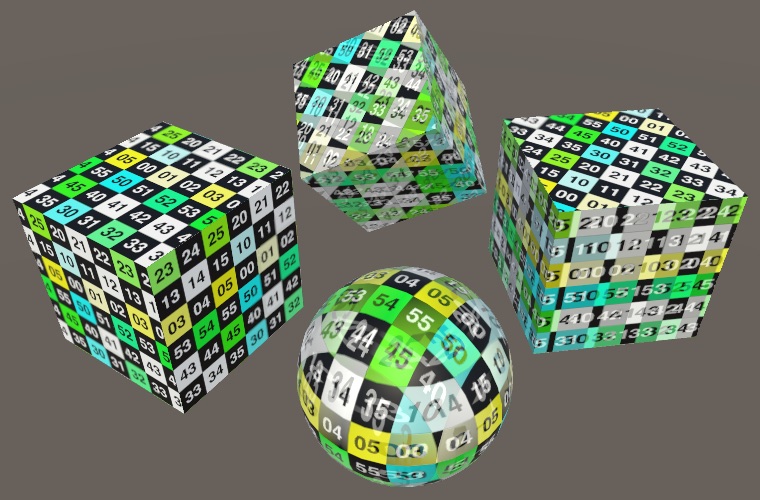
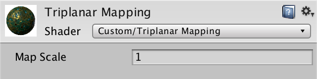
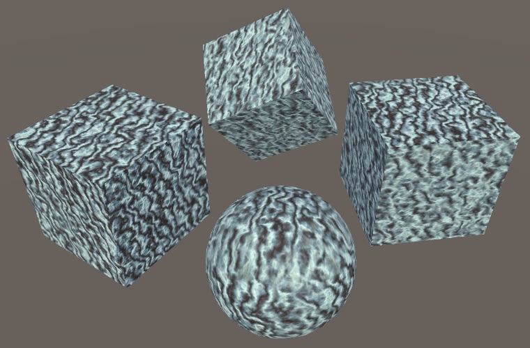
Create a material with our new shader and try it out. I've use the old test texture as the material's main texture, though it doesn't get used at this point.
Texturing With Three Planes
How can we perform texture mapping when vertex UV coordinates are unavailable? We have to use a substitute. The only viable approach is to use the world position—or maybe the object-space position—as an alternative source of UV coordinates for texture mapping.
Texture Mapping Based on Position
The world position of a fragment is a 3D vector, but regular texture mapping is done in 2D. So we have to choose two dimensions to use as UV coordinates, which means that we map the texture onto a plane in 3D space. The most obvious choice is the use the XY coordinates.
surface.albedo = tex2D(_MainTex, parameters.position.xy);
The result is that we see the texture projected along the Z axis. But this is not the only possible orientation. We could also project along the Y axis, by using the XZ coordinates instead. This corresponds to the planar texture mapping often used to texture terrains.
surface.albedo = tex2D(_MainTex, parameters.position.xz);
And the third option is to project along X, by using the YZ coordinates.
surface.albedo = tex2D(_MainTex, parameters.position.yz);
But when we use YZ we end up with the texture rotated 90°. To keep the orientation as expected, we have to use ZY instead.
surface.albedo = tex2D(_MainTex, parameters.position.zy);
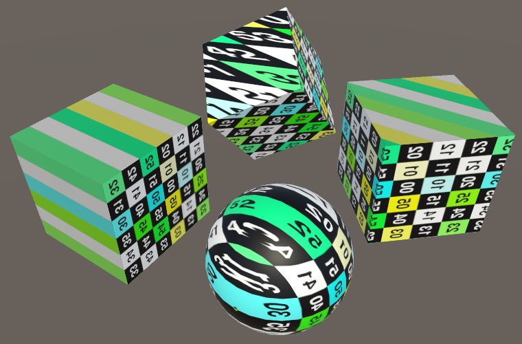
Combining All Three Mappings
A single-planar mapping works well when a surface is mostly aligned with the projection axis, but looks horrible when it isn't. When the results are bad along one axis, they might be better along another axis. So it's useful to support all three mappings, which requires us to provide three different UV coordinate pairs.
Let's keep the logic to determine these UV coordinates separate. Create a TriplanarUV struct with coordinate pairs for all three axes. Then make a GetTriplanarUV function that sets up the UV based on the surface parameters.
struct TriplanarUV {
	float2 x, y, z;
};

TriplanarUV GetTriplanarUV (SurfaceParameters parameters) {
	TriplanarUV triUV;
	float3 p = parameters.position;
	triUV.x = p.zy;
	triUV.y = p.xz;
	triUV.z = p.xy;
	return triUV;
}
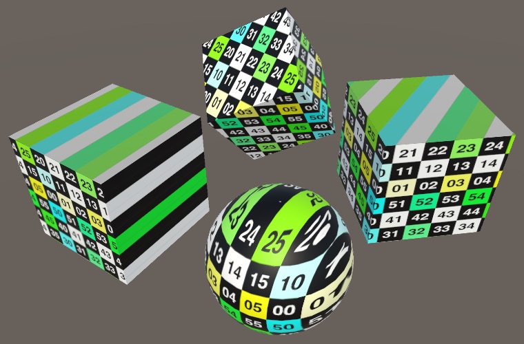
Use this function in MyTriPlanarSurfaceFunction and just sample using all three projections. The final albedo then becomes their average.
void MyTriPlanarSurfaceFunction (
	inout SurfaceData surface, SurfaceParameters parameters
) {
	TriplanarUV triUV = GetTriplanarUV(parameters);

	float3 albedoX = tex2D(_MainTex, triUV.x).rgb;
	float3 albedoY = tex2D(_MainTex, triUV.y).rgb;
	float3 albedoZ = tex2D(_MainTex, triUV.z).rgb;

	surface.albedo = (albedoX + albedoY + albedoZ) / 3;
	…
}
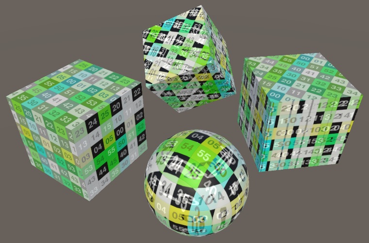
Blending Based on Normal
We now always get the best projection, but also the other two. We cannot only use the best one, because they we'd get seams where what's best suddenly changes. But what we can do is smoothly blend between them.
The preferred mapping is the one that best aligns with the surface orientation, which is indicated by the surface normal. So we could use the normal to define the weights of all three projections. We have to use the absolute of the normal vector, because a surface can face a negative direction. Also, the total of the weights has to sum to 1, so we have to normalize them via division by their total. Create a new function to compute these weights.
float3 GetTriplanarWeights (SurfaceParameters parameters) {
	float3 triW = abs(parameters.normal);
	return triW / (triW.x + triW.y + triW.z);
}
Now we can modulate the contribution of each mapping by its weight.
void MyTriPlanarSurfaceFunction (
	inout SurfaceData surface, SurfaceParameters parameters
) {
	…

	float3 triW = GetTriplanarWeights(parameters);

	surface.albedo = albedoX * triW.x + albedoY * triW.y + albedoZ * triW.z;
	…
}
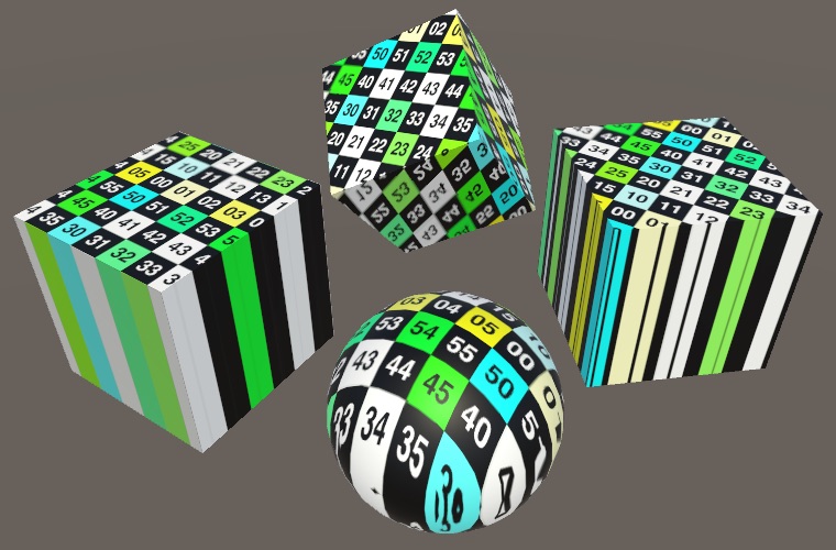
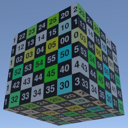
Mirrored Mapping
The best possible projection is now strongest. On axis-aligned surfaces, we end up seeing only a single mapping. An axis-aligned cube looks good on all sides, except that half of them end up with a mirrored mapping.
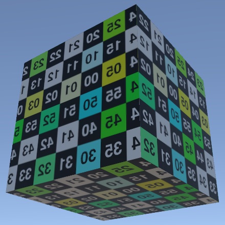
It isn't always a problem when a texture gets mirrored, but it's obvious when using our test texture with numbers on it. So let's make sure that textures are never mirrored. We do this by negating the U coordinate when appropriate. In case of the X mapping, that's when normal.x is negative. Likewise for the Y projection, when normal.y is negative. It's the opposite for Z.
TriplanarUV GetTriplanarUV (SurfaceParameters parameters) {
	TriplanarUV triUV;
	float3 p = parameters.position;
	triUV.x = p.zy;
	triUV.y = p.xz;
	triUV.z = p.xy;
	if (parameters.normal.x < 0) {
		triUV.x.x = -triUV.x.x;
	}
	if (parameters.normal.y < 0) {
		triUV.y.x = -triUV.y.x;
	}
	if (parameters.normal.z >= 0) {
		triUV.z.x = -triUV.z.x;
	}
	return triUV;
}
Note that this produces a seam in each mapping where its dimension is zero, but that's fine because their weight is zero there as well.
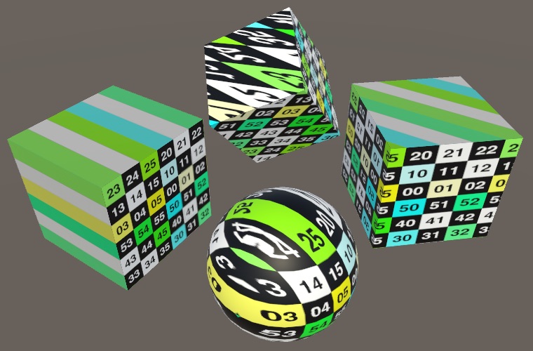
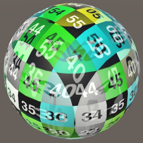
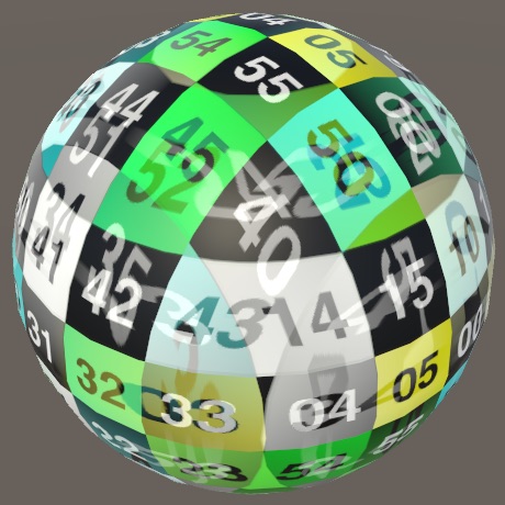
Offsetting Maps
Because we're projecting the same texture on a surface three times, we can end up with sudden repetitions. This can be quite obvious on a sphere. You can move it around until you end up with a texture alignment like in the below screenshot. From left to right, you can see the sequences 44, 45, 40, 44, 45, 40, even though the compete sequence is 40–45. And below that you can see 34, 35, 30, 34, 35, 30. And vertically you can see 44 and 45 repeated.
We can eliminate such repetitions by offsetting the projections. If we shift the X mapping by ½ vertically, then we eliminate them between X and Z. Likewise for Y and Z if we shift X by ½ horizontally. The X and Y mappings aren't aligned, so we don't have to worry about those.
TriplanarUV GetTriplanarUV (SurfaceParameters parameters) {
	…
	triUV.x.y += 0.5;
	triUV.z.x += 0.5;
	return triUV;
}
We used ½ as an offset because that's the maximum. In case of our test texture, it breaks the number sequences but keeps the blocks aligned. Had we used a texture with three instead of six obvious bands, offsetting by ⅓ would've looked better. Usually, triplanar mapping is done with terrain textures, for which you don't have to worry about exact alignment.
Other Surface Properties
Besides albedo, there are more surface properties that could be stored in maps. For example, for our circuitry materials we also have metallic, occlusion, smoothness, and normal maps. Let's support those as well.
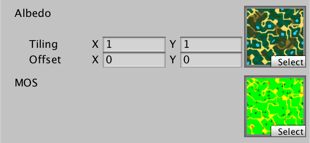
MOS Maps
When using triplanar mapping, we sample maps using three different projections. This triples the amount of texture sampling in the shader. To keep this manageable, we should aim to minimize the amount of samples per projection. We can do this by storing multiple surface properties in a single map. We already have such a map for our circuitry material, storing metallic in the R channel, occlusion in G, and smoothness in A. So that's a Metallic-Occlusion-Smoothness map, or MOS map for short. We'll rely on such a MOS map in our triplanar shader, so add it as a property.
	Properties {
		_MainTex ("Albedo", 2D) = "white" {}
		[NoTilingOffset] _MOSMap ("MOS", 2D) = "white" {}
	}
Add a variable for this map—as it is not defined in My Lighting Input—then sample it three times, just like the albedo map.
sampler2D _MOSMap;

…

void MyTriPlanarSurfaceFunction (
	inout SurfaceData surface, SurfaceParameters parameters
) {
	TriplanarUV triUV = GetTriplanarUV(parameters);

	float3 albedoX = tex2D(_MainTex, triUV.x).rgb;
	float3 albedoY = tex2D(_MainTex, triUV.y).rgb;
	float3 albedoZ = tex2D(_MainTex, triUV.z).rgb;

	float4 mosX = tex2D(_MOSMap, triUV.x);
	float4 mosY = tex2D(_MOSMap, triUV.y);
	float4 mosZ = tex2D(_MOSMap, triUV.z);

	…
}
Blend the MOS data using the triplanar weights, then use the result to setup the surface.
	surface.albedo = albedoX * triW.x + albedoY * triW.y + albedoZ * triW.z;

	float4 mos = mosX * triW.x + mosY * triW.y + mosZ * triW.z;
	surface.metallic = mos.x;
	surface.occlusion = mos.y;
	surface.smoothness = mos.a;
Normal Maps
Add support for a normal map as well. We cannot pack that in another map, so it needs its own property.
	Properties {
		_MainTex ("Albedo", 2D) = "white" {}
		[NoTilingOffset] _MOSMap ("MOS", 2D) = "white" {}
		[NoTilingOffset] _NormalMap ("Normals", 2D) = "white" {}
	}
Sample the map three times, and unpack the normal for each axis.
void MyTriPlanarSurfaceFunction (
	inout SurfaceData surface, SurfaceParameters parameters
) {
	…

	float4 mosX = tex2D(_MOSMap, triUV.x);
	float4 mosY = tex2D(_MOSMap, triUV.y);
	float4 mosZ = tex2D(_MOSMap, triUV.z);

	float3 tangentNormalX = UnpackNormal(tex2D(_NormalMap, triUV.x));
	float3 tangentNormalY = UnpackNormal(tex2D(_NormalMap, triUV.y));
	float3 tangentNormalZ = UnpackNormal(tex2D(_NormalMap, triUV.z));

	…
}
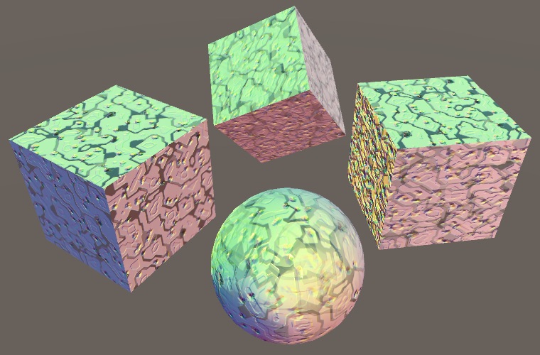
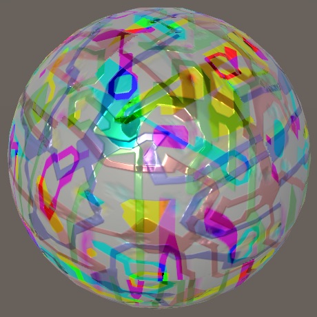
We can blend the normal the same way as the other data, we just have to normalize it too. However, that would only work for world-space normals, while what we sampled are tangent-space normals. Let's begin by assuming we can directly use them as world-space normals and see what happens. To make it more obvious, again use the normal for albedo as well.
	float3 tangentNormalX = UnpackNormal(tex2D(_NormalMap, triUV.x));
	float3 tangentNormalY = UnpackNormal(tex2D(_NormalMap, triUV.y));
	float3 tangentNormalZ = UnpackNormal(tex2D(_NormalMap, triUV.z));

	float3 worldNormalX = tangentNormalX;
	float3 worldNormalY = tangentNormalY;
	float3 worldNormalZ = tangentNormalZ;

	float3 triW = GetTriplanarWeights(parameters);

	…

	surface.normal = normalize(
		worldNormalX * triW.x + worldNormalY * triW.y + worldNormalZ * triW.z
	);
	surface.albedo = surface.normal * 0.5 + 0.5;
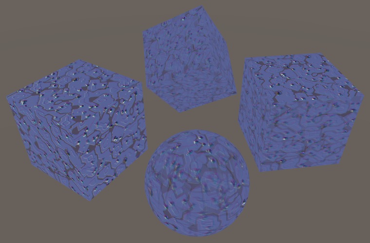
The final normal vectors are incorrect. The tangent space normals are stored with their local up direction—away from the surface—in the Z channel, so the result is mostly blue. This matches the XYZ orientation of the Z projection, but not the other two.
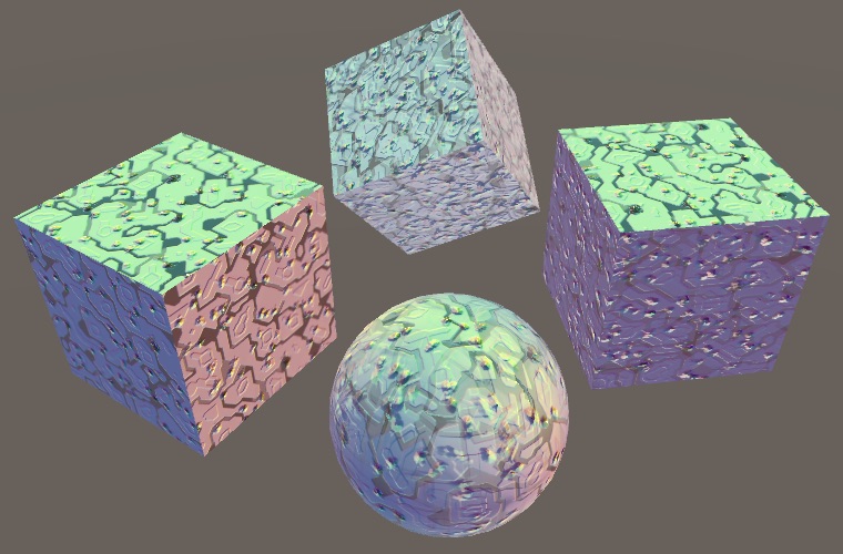
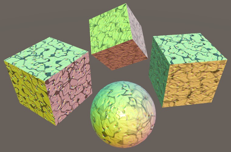
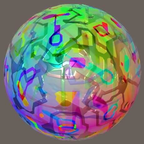
In the case of the Y projection, the up direction corresponds to Y, not Z. So we have to swap Y and Z to convert from tangent space to world space. Likewise, we have to swap X and Z for the X projection.
	float3 tangentNormalX = UnpackNormal(tex2D(_NormalMap, triUV.x));
	float3 tangentNormalY = UnpackNormal(tex2D(_NormalMap, triUV.y));
	float3 tangentNormalZ = UnpackNormal(tex2D(_NormalMap, triUV.z));

	float3 worldNormalX = tangentNormalX.zyx;
	float3 worldNormalY = tangentNormalY.xzy;
	float3 worldNormalZ = tangentNormalZ;
Because we negated the X coordinates to prevent mirroring, we also have to do this for the tangent-space normal vectors. Otherwise those would still be mirrored.
	float3 tangentNormalX = UnpackNormal(tex2D(_NormalMap, triUV.x));
	float3 tangentNormalY = UnpackNormal(tex2D(_NormalMap, triUV.y));
	float3 tangentNormalZ = UnpackNormal(tex2D(_NormalMap, triUV.z));

	if (parameters.normal.x < 0) {
		tangentNormalX.x = -tangentNormalX.x;
	}
	if (parameters.normal.y < 0) {
		tangentNormalY.x = -tangentNormalY.x;
	}
	if (parameters.normal.z >= 0) {
		tangentNormalZ.x = -tangentNormalZ.x;
	}

	float3 worldNormalX = tangentNormalX.zyx;
	float3 worldNormalY = tangentNormalY.xzy;
	float3 worldNormalZ = tangentNormalZ;
In those cases we also have to flip the normal's up direction, as they're pointing inwards.
	if (parameters.normal.x < 0) {
		tangentNormalX.x = -tangentNormalX.x;
		tangentNormalX.z = -tangentNormalX.z;
	}
	if (parameters.normal.y < 0) {
		tangentNormalY.x = -tangentNormalY.x;
		tangentNormalY.z = -tangentNormalY.z;
	}
	if (parameters.normal.z >= 0) {
		tangentNormalZ.x = -tangentNormalZ.x;
	}
	else {
		tangentNormalZ.z = -tangentNormalZ.z;
	}
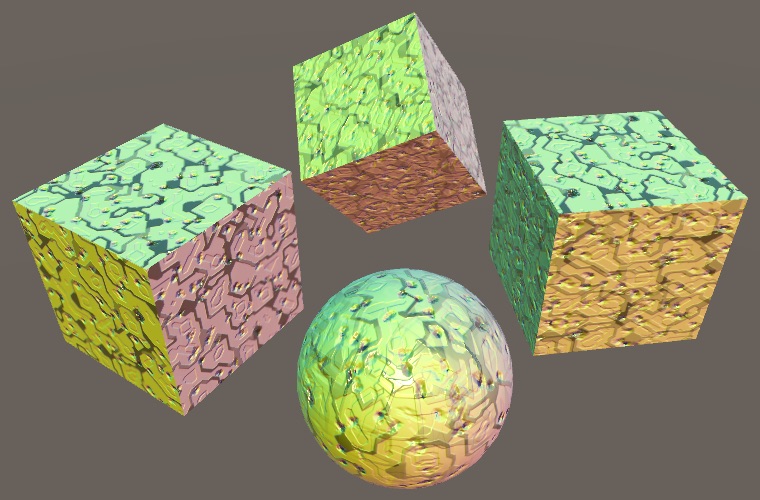
Blending With Surface Normal
Although the normal vectors are now correctly aligned with their projection, they have nothing to do with the actual surface normal. For example, a sphere ends up with normals like a cube. This isn't directly obvious because we're smoothly blending between these normals based on the actual surface normal, but it will become worse when we'll adjust the blending.
Usually, we'd rely on a tangent-to-world transformation matrix to make the normals fit the geometry's surface. But we do not have such matrices for our three projections. What we can do instead is blend between each projected normal and the surface normal, using whiteout blending. We could use the BlendNormals function for this, but it also normalizes the result. That's a bit much, considering we blend the three results and then normalize that again. So let's make our own variant that doesn't normalize per projection.
float3 BlendTriplanarNormal (float3 mappedNormal, float3 surfaceNormal) {
	float3 n;
	n.xy = mappedNormal.xy + surfaceNormal.xy;
	n.z = mappedNormal.z * surfaceNormal.z;
	return n;
}
Whiteout blending assumes Z is pointing up. So convert the surface normal to the projected space, perform the blend in this tangent space, then convert the result to world space.
	float3 worldNormalX =
		BlendTriplanarNormal(tangentNormalX, parameters.normal.zyx).zyx;
	float3 worldNormalY =
		BlendTriplanarNormal(tangentNormalY, parameters.normal.xzy).xzy;
	float3 worldNormalZ =
		BlendTriplanarNormal(tangentNormalZ, parameters.normal);
This goes wrong for surfaces facing a negative direction, because then we end up multiplying two negative Z values, flipping the sign of the final Z. We can solve this by using the absolute of one of the Z values. But this is equivalent to not negating the sampled Z components to begin with, so we can just remove that code.
	if (parameters.normal.x < 0) {
		tangentNormalX.x = -tangentNormalX.x;
//		tangentNormalX.z = -tangentNormalX.z;
	}
	if (parameters.normal.y < 0) {
		tangentNormalY.x = -tangentNormalY.x;
//		tangentNormalY.z = -tangentNormalY.z;
	}
	if (parameters.normal.z >= 0) {
		tangentNormalZ.x = -tangentNormalZ.x;
	}
//	else {
//		tangentNormalZ.z = -tangentNormalZ.z;
//	}
The resulting normal vectors are now biased towards the original surface normal. Although this isn't perfect, it's usually sufficient. You could go a step further and completely drop the sampled Z components, only using the original Z component. That's known as UDN blending, which is cheaper when using DXT5nm compression because the Z component doesn't need to be reconstructed, but deceases the strength of the normals for non-aligned surfaces.
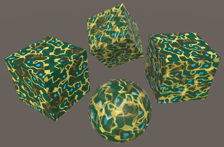
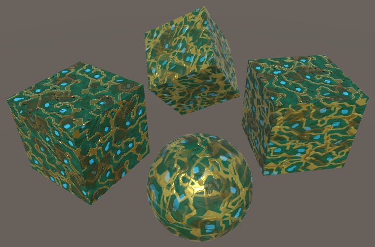
With the normal maps functional, restore the original albedo so we can see the complete circuitry material.
// surface.albedo = surface.normal * 0.5 + 0.5;
Scaling Maps
Finally, let's make it possible to scale the maps. Usually, this is done via the tiling and offset values of a single texture, but this doesn't make much sense for triplanar mapping. An offset isn't very useful and neither is a nonuniform scale. So let's use a single scale property instead.
	Properties {
		[NoScaleOffset] _MainTex ("Albedo", 2D) = "white" {}
		[NoScaleOffset] _MOSMap ("MOS", 2D) = "white" {}
		[NoScaleOffset] _NormalMap ("Normals", 2D) = "white" {}

		_MapScale ("Map Scale", Float) = 1
	}
Add the required variable for the map scale and use it to scale the position when determining the UV coordinates.
float _MapScale;

struct TriplanarUV {
	float2 x, y, z;
};

TriplanarUV GetTriplanarUV (SurfaceParameters parameters) {
	TriplanarUV triUV;
	float3 p = parameters.position * _MapScale;
	…
}
Adjusting Blend Weights
The final surface data is found by blending between the three mappings, using the original surface normal. So far we've use the normal directly, only taking its absolute value and normalizing the result so the weights sum to 1. That's the most straightforward approach, but it's also possible to tweak the weights in various ways.
Blend Offset
The first way to change how the weights are calculated is by introducing an offset. If we subtract the same amount from all weights, then smaller weights are affected more than larger weights, which changes their relative importance. They could even become negative. Add a blend offset property to make this possible.
We must ensure that not all weights become negative, so the maximum offset should be less than the maximum possible smallest weight, which is when all three components of the normal vector are equal. That's √⅓ which is about 0.577, but let's just use 0.5 as the maximum, with 0.25 as the default.
		_MapScale ("Map Scale", Float) = 1

		_BlendOffset ("Blend Offset", Range(0, 0.5)) = 0.25
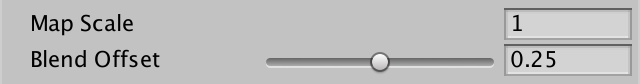
Subtract the offset from the weights before normalizing them, and see what that looks like.
float _BlendOffset;

…

float3 GetTriplanarWeights (SurfaceParameters parameters) {
	float3 triW = abs(parameters.normal);
	triW = triW - _BlendOffset;
	return triW / (triW.x + triW.y + triW.z);
}
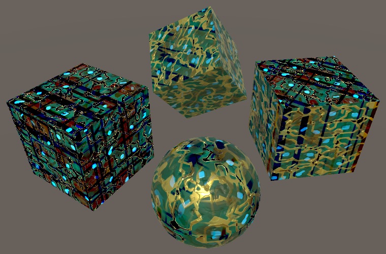
It looks fine when blend weights remain positive, but negative weights end up subtracting from the final data. To prevent this, clamp the weights before normalizing.
triW = saturate(triW - _BlendOffset);
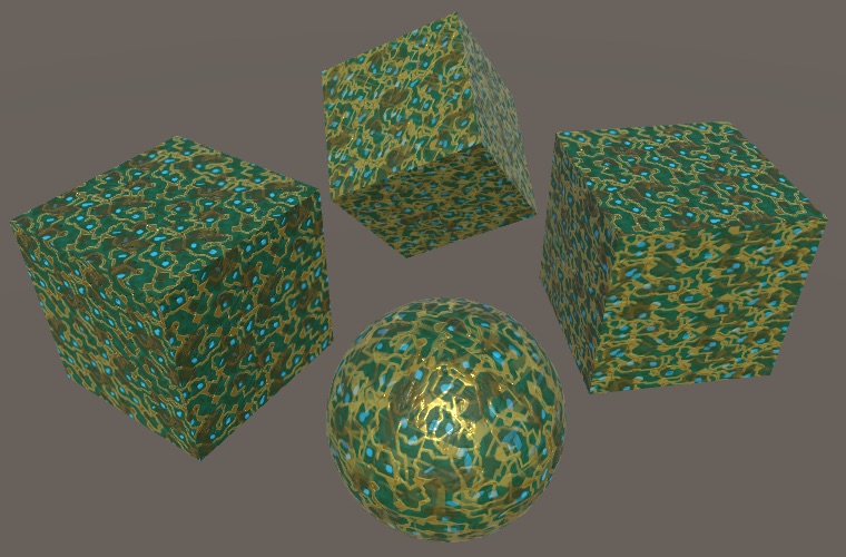
The result is that the higher the offset, the smaller the blend region becomes. To more clearly see how the blending changes, use the weights for albedo.
void MyTriPlanarSurfaceFunction (
	inout SurfaceData surface, SurfaceParameters parameters
) {
	…
	surface.albedo = triW;
}
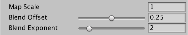
Blend Exponent
Another way to decrease the blend region is via exponentiation, by raising the weights to some power higher than 1 before normalizing. This works like an offset, but is nonlinear. Add a shader property for it, using an arbitrary maximum of 8 and a default of 2.
		_BlendOffset ("Blend Offset", Range(0, 0.5)) = 0.25
		_BlendExponent ("Blend Exponent", Range(1, 8)) = 2
Use the pow function to apply the exponent, after offsetting.
float _BlendOffset, _BlendExponent;

…

float3 GetTriplanarWeights (SurfaceParameters parameters) {
	float3 triW = abs(parameters.normal);
	triW = saturate(triW - _BlendOffset);
	triW = pow(triW, _BlendExponent);
	return triW / (triW.x + triW.y + triW.z);
}
You might end up using either of both approaches together to tune the blend weights. If you settle on a final exponent of 2, 4, or 8, you could hard-code this with a few multiplications instead of relying on pow.
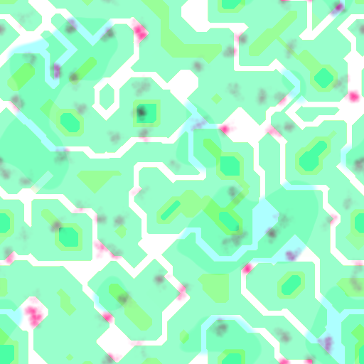
Blending Based on Height
Besides relying on the original surface normal, we could also have the surface data influence the blend. If the surface data included height, then that could be factored into the weights. Our MOS maps still have an unused channel, so it's possible to turn them into MOHS maps, containing metallic, occlusion, height, and smoothness data. Here is such a map for our circuitry material. It's the same as the MOS map, but with height data in the blue channel.
Rename our MOS property to MOHS and assign the new texture. Make sure that its sRGB import checkbox is disabled.
		[NoScaleOffset] _MainTex ("Albedo", 2D) = "white" {}
		[NoScaleOffset] _MOHSMap ("MOHS", 2D) = "white" {}
		[NoScaleOffset] _NormalMap ("Normals", 2D) = "white" {}
Also rename the variables.
sampler2D _MOHSMap;

…

void MyTriPlanarSurfaceFunction (
	inout SurfaceData surface, SurfaceParameters parameters
) {
	…

	float4 mohsX = tex2D(_MOHSMap, triUV.x);
	float4 mohsY = tex2D(_MOHSMap, triUV.y);
	float4 mohsZ = tex2D(_MOHSMap, triUV.z);

	…

	float4 mohs = mohsX * triW.x + mohsY * triW.y + mohsZ * triW.z;
	surface.metallic = mohs.x;
	surface.occlusion = mohs.y;
	surface.smoothness = mohs.a;

	…
}
Add parameters for the three height values to GetTriplanarWeights. Let's begin by using the heights directly, replacing the normal vector, before exponentiation.
float3 GetTriplanarWeights (
	SurfaceParameters parameters, float heightX, float heightY, float heightZ
) {
	float3 triW = abs(parameters.normal);
	triW = saturate(triW - _BlendOffset);
	triW = float3(heightX, heightY, heightZ);
	triW = pow(triW, _BlendExponent);
	return triW / (triW.x + triW.y + triW.z);
}
Then add the heights as arguments when invoking the function.
float3 triW = GetTriplanarWeights(parameters, mohsX.z, mohsY.z, mohsZ.z);
Using only the heights doesn't give us a useful result, but makes it clear that the golden circuitry strips are highest and thus dominate the blend. Now multiply the heights with their respective weights.
triW *= float3(heightX, heightY, heightZ);
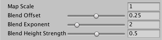
This looks much better, but the influence of the heights is still very strong. It's useful to modulate this, so add a Blend Height Strength property to our shader. At full strength it could completely eliminate some weights, which shouldn't happen. So limit the strength's range to 0–0.99, with a default of 0.5.
		_BlendOffset ("Blend Offset", Range(0, 0.5)) = 0.25
		_BlendExponent ("Blend Exponent", Range(1, 8)) = 2
		_BlendHeightStrength ("Blend Height Strength", Range(0, 0.99)) = 0.5
Apply the strength by interpolating between 1 and the heights, using the strength as the interpolator. Then multiply the weights with that.
float _BlendOffset, _BlendExponent, _BlendHeightStrength;

…

float3 GetTriplanarWeights (
	SurfaceParameters parameters, float heightX, float heightY, float heightZ
) {
	float3 triW = abs(parameters.normal);
	triW = saturate(triW - _BlendOffset);
	triW *= lerp(1, float3(heightX, heightY, heightZ), _BlendHeightStrength);
	triW = pow(triW, _BlendExponent);
	return triW / (triW.x + triW.y + triW.z);
}
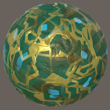
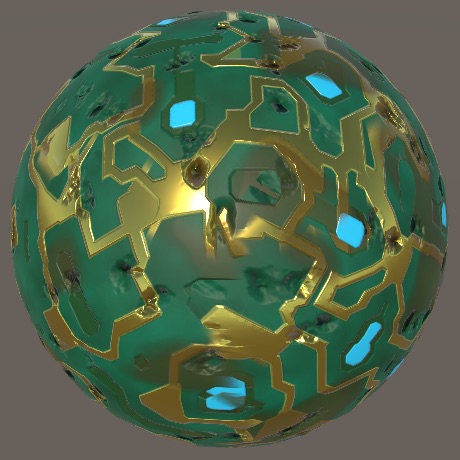
Using heights works best in combination with an offset to limit the range of their influence. Besides that, a higher exponent makes the effect more pronounced.
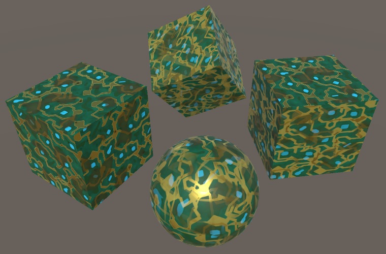
Finally, restore the albedo to see the effect of the blend settings on the complete material.
// surface.albedo = triW;
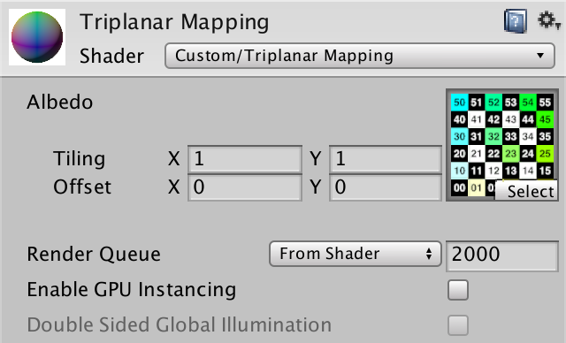
Custom Shader GUI
We didn't use the shader GUI class that we created for our other shaders, because it wouldn't work with our triplanar shader. It relies on properties that our triplanar shader doesn't have. While we could make MyLightingShaderGUI also support this shader, it's better to keep it simple and create a new class.
Base Class
Instead of copying the base functionality of MyLightingShaderGUI that we could reuse, we'll create a common base class that both our GUIs can extend. Let's name it MyBaseShaderGUI. Put all general-purpose code from MyLightingShaderGUI into it and omit the rest. Make everything that should be directly available to its subclasses protected. That allows access by the class itself and its subclasses, but from nowhere else.
using UnityEngine;//using UnityEngine.Rendering;using UnityEditor; public class MyBaseShaderGUI : ShaderGUI { static GUIContent staticLabel = new GUIContent(); protected Material target; protected MaterialEditor editor; MaterialProperty[] properties; public override void OnGUI ( MaterialEditor editor, MaterialProperty[] properties ) { this.target = editor.target as Material; this.editor = editor; this.properties = properties;// DoRenderingMode();// …// DoAdvanced();} protected MaterialProperty FindProperty (string name) { return FindProperty(name, properties); } protected static GUIContent MakeLabel (string text, string tooltip = null) { … } protected static GUIContent MakeLabel ( MaterialProperty property, string tooltip = null ) { … } protected void SetKeyword (string keyword, bool state) { … } protected bool IsKeywordEnabled (string keyword) { return target.IsKeywordEnabled(keyword); } protected void RecordAction (string label) { editor.RegisterPropertyChangeUndo(label); } }
Have MyLightingShaderGUI extend MyBaseShaderGUI instead of ShaderGUI directly. Then remove all code from it that is now part of its base class. Instead of setting up the variables itself in OnGUI, delegate that to the OnGUI method of its base class, by invoking base.OnGUI.
public class MyLightingShaderGUI : MyBaseShaderGUI {

	…

	public override void OnGUI (
		MaterialEditor editor, MaterialProperty[] properties
	) {
//		this.target = editor.target as Material;
//		this.editor = editor;
//		this.properties = properties;
		base.OnGUI(editor, properties);
		DoRenderingMode();
		…
		DoAdvanced();
	}

	…
}
Triplanar Shader GUI
Add a new MyTriplanarShaderGUI class to create the GUI for our triplanar shader. Have it extend MyBaseShaderGUI. Give it an OnGUI method in which it invokes base.OnGUI and then shows the map scale property. Use separate methods for the maps, blending, and other settings.
using UnityEngine;
using UnityEditor;
public class MyTriplanarShaderGUI : MyBaseShaderGUI {
public override void OnGUI (
MaterialEditor editor, MaterialProperty[] properties
) {
base.OnGUI(editor, properties);
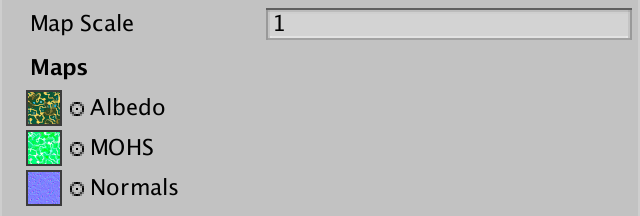
editor.ShaderProperty(FindProperty("_MapScale"), MakeLabel("Map Scale"));
DoMaps();
DoBlending();
DoOtherSettings();
}
void DoMaps () {}
void DoBlending () {}
void DoOtherSettings () {}
}
Declare this class to be the custom editor for our triplanar shader.
Shader "Custom/Triplanar Mapping" {

	…

	CustomEditor "MyTriplanarShaderGUI"
}
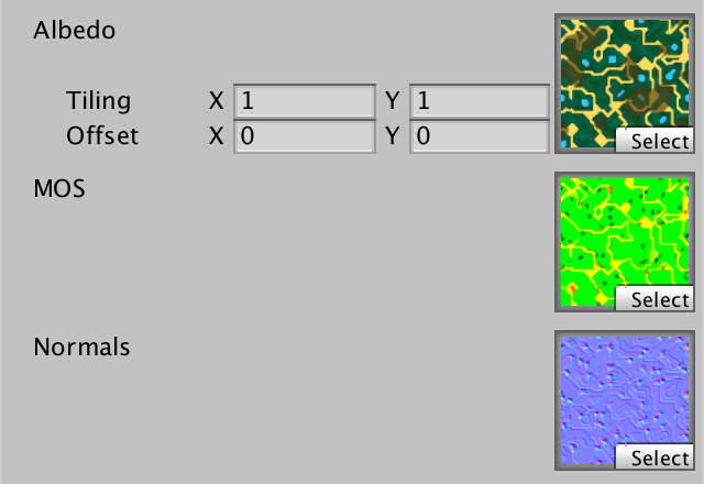
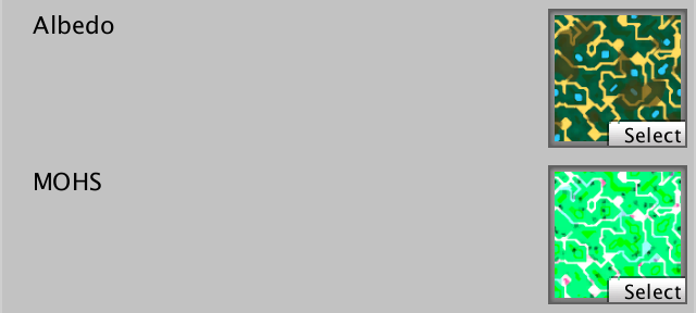
Maps
Create a label for the map section and then show the three texture properties, each on a single line. Give the MOHS map a tooltip to explain what each channel should contain.
void DoMaps () {
GUILayout.Label("Maps", EditorStyles.boldLabel);
editor.TexturePropertySingleLine(
MakeLabel("Albedo"), FindProperty("_MainTex")
);
editor.TexturePropertySingleLine(
MakeLabel(
"MOHS",
"Metallic (R) Occlusion (G) Height (B) Smoothness (A)"
),
FindProperty("_MOHSMap")
);
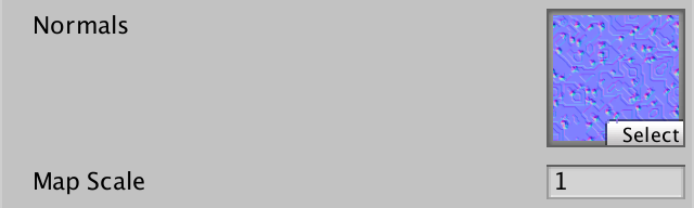
editor.TexturePropertySingleLine(
MakeLabel("Normals"), FindProperty("_NormalMap")
);
}
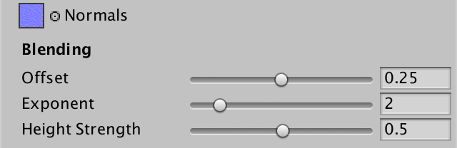
Blending
The blending section is simple, just a label and the three properties.
	void DoBlending () {
		GUILayout.Label("Blending", EditorStyles.boldLabel);

		editor.ShaderProperty(FindProperty("_BlendOffset"), MakeLabel("Offset"));
		editor.ShaderProperty(
			FindProperty("_BlendExponent"), MakeLabel("Exponent")
		);
		editor.ShaderProperty(
			FindProperty("_BlendHeightStrength"), MakeLabel("Height Strength")
		);
	}
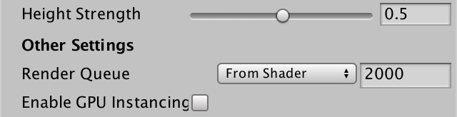
Other Settings
For other settings, allow the customization of the render queue, by invoking MaterialEditor.RenderQueueField. Also make it possible to toggle GPU instancing.
	void DoOtherSettings () {
		GUILayout.Label("Other Settings", EditorStyles.boldLabel);

		editor.RenderQueueField();
		editor.EnableInstancingField();	}
Separate Top Maps
Often, you don't want a completely uniform appearance. The obvious case is terrain, where horizontal surfaces—those pointing up, not down—could be grass while all other surfaces could be rock. You might even want to combine triplanar mapping with texture splatting, but that's expensive because it would require a lot more texture sampling. Alternative approaches are to rely on decals, other detail objects, or vertex colors to add variety.
More Maps
To support a separate top map, we need to add three alternative map properties.
		[NoScaleOffset] _MainTex ("Albedo", 2D) = "white" {}
		[NoScaleOffset] _MOHSMap ("MOHS", 2D) = "white" {}
		[NoScaleOffset] _NormalMap ("Normals", 2D) = "white" {}

		[NoScaleOffset] _TopMainTex ("Top Albedo", 2D) = "white" {}
		[NoScaleOffset] _TopMOHSMap ("Top MOHS", 2D) = "white" {}
		[NoScaleOffset] _TopNormalMap ("Top Normals", 2D) = "white" {}
Separate top maps aren't always needed, so let's make that a shader feature, using the _SEPARATE_TOP_MAP keyword. Add support for it to all passes, except the shadow pass.
			#pragma target 3.0

			#pragma shader_feature _SEPARATE_TOP_MAPS
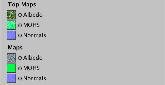
Add these extra maps to our shader GUI. Use the top albedo map to determine whether the keyword should be set.
	void DoMaps () {
		GUILayout.Label("Top Maps", EditorStyles.boldLabel);

		MaterialProperty topAlbedo = FindProperty("_TopMainTex");
		Texture topTexture = topAlbedo.textureValue;
		EditorGUI.BeginChangeCheck();
		editor.TexturePropertySingleLine(MakeLabel("Albedo"), topAlbedo);
		if (EditorGUI.EndChangeCheck() && topTexture != topAlbedo.textureValue) {
			SetKeyword("_SEPARATE_TOP_MAPS", topAlbedo.textureValue);
		}
		editor.TexturePropertySingleLine(
			MakeLabel(
				"MOHS",
				"Metallic (R) Occlusion (G) Height (B) Smoothness (A)"
			),
			FindProperty("_TopMOHSMap")
		);
		editor.TexturePropertySingleLine(
			MakeLabel("Normals"), FindProperty("_TopNormalMap")
		);

		GUILayout.Label("Maps", EditorStyles.boldLabel);

		…
	}
Using Marble
To see separate top maps in action, we need another set of textures. We can use the marble albedo and normal maps. Here is a matching MOHS map.

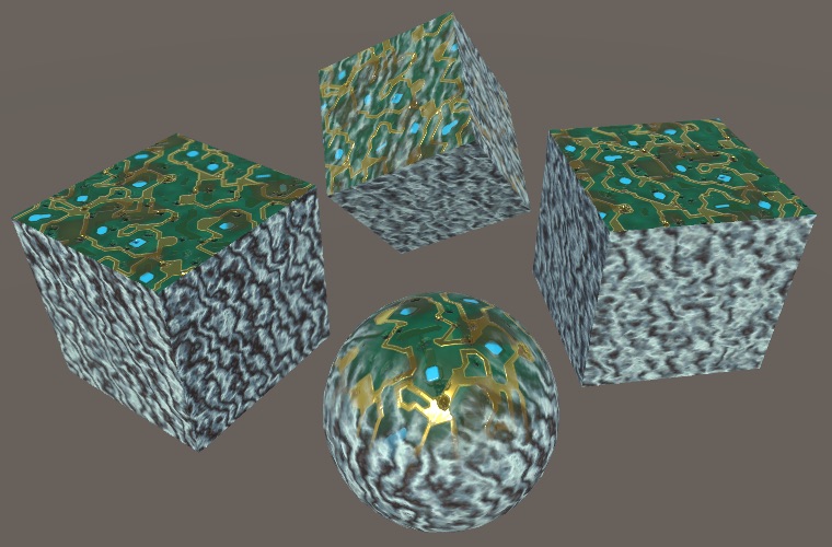
Use circuitry for the top—as it's green, so somewhat like grass—and marble for the rest.
As the shader doesn't know about the top maps yet, we currently see only marble.
Enabling Top Maps
Add the required sampler variables to MyTriplanarMapping. Check whether the keyword is defined in MyTriPlanarSurfaceFunction, after all textures have been sampled. If so, add code to overwrite the data for the Y projection with samples from the top maps. But only do this for surfaces that point upward, so when the surface normal has a positive Y component.
sampler2D _TopMainTex, _TopMOHSMap, _TopNormalMap;
…

void MyTriPlanarSurfaceFunction (
	inout SurfaceData surface, SurfaceParameters parameters
) {
	…
	float3 tangentNormalZ = UnpackNormal(tex2D(_NormalMap, triUV.z));

	#if defined(_SEPARATE_TOP_MAPS)
		if (parameters.normal.y > 0) {
			albedoY = tex2D(_TopMainTex, triUV.y).rgb;
			mohsY = tex2D(_TopMOHSMap, triUV.y);
			tangentNormalY = UnpackNormal(tex2D(_TopNormalMap, triUV.y));
		}
	#endif
}
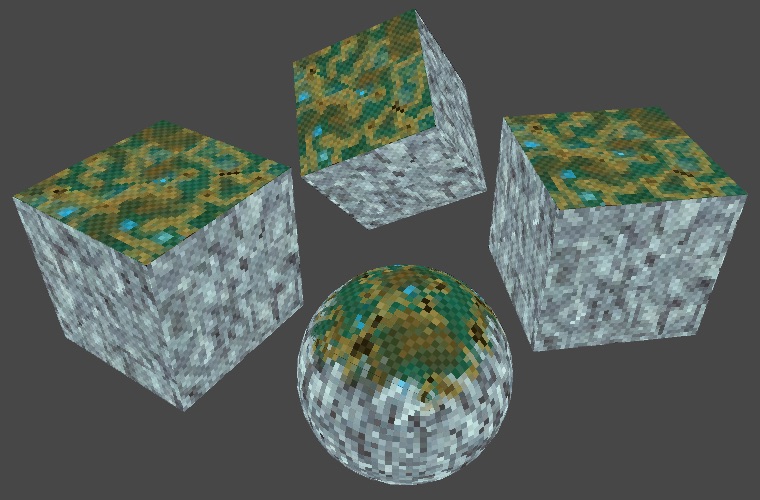
This results in a shader that samples either the regular or the top maps for its Y projection. In our case, we get a circuitry layer on top of marble. Typically it would be grass, sand, or snow.
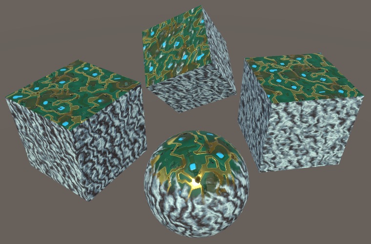
The default blend settings produce a rather smooth blend between the projections, which doesn't look good where circuitry and marble meet. An exponent of 8 results in a much more sudden transition, which suits the materials better. It's also possible to support different blend settings for the top maps, but the height blending already allows a lot of control via the MOHS maps.
Unpacking Later
Although the shader compiler uses an if-else approach to smartly sample either the top or regular maps, it isn't smart about unpacking the normal. It cannot assume that both uses of UnpackNormal can be combined. To help the compiler, we can postpone unpacking the raw normal until after the choice of maps.
float3 tangentNormalX = UnpackNormal(tex2D(_NormalMap, triUV.x));// float3 tangentNormalY = UnpackNormal(tex2D(_NormalMap, triUV.y));float4 rawNormalY = tex2D(_NormalMap, triUV.y); float3 tangentNormalZ = UnpackNormal(tex2D(_NormalMap, triUV.z)); #if defined(_SEPARATE_TOP_MAPS) if (parameters.normal.y > 0) { albedoY = tex2D(_TopMainTex, triUV.y).rgb; mohsY = tex2D(_TopMOHSMap, triUV.y);// tangentNormalY = UnpackNormal(tex2D(_TopNormalMap, triUV.y));rawNormalY = tex2D(_TopNormalMap, triUV.y); } #endif float3 tangentNormalY = UnpackNormal(rawNormalY);
Lightmapping
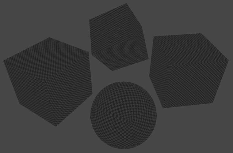
Our triplanar shader isn't finished, because it doesn't support lightmapping yet. It can receive baked light, but doesn't contribute to it. It's easiest to see this by making all objects static and switching the directional light to baked mode. Wait until baking is finished, then check the baked albedo, by switching the scene view mode from Shaded to Baked Global Illumination / Albedo. All objects that use triplanar mapping turn out to be black.
To support lightmapping, we have to add a meta pass to our shader, which has to rely on My Lightmapping instead of My Lighting.
		Pass {
			Tags {
				"LightMode" = "Meta"
			}

			Cull Off

			CGPROGRAM

			#pragma vertex MyLightmappingVertexProgram
			#pragma fragment MyLightmappingFragmentProgram

			#pragma shader_feature _SEPARATE_TOP_MAPS

			#include "MyTriplanarMapping.cginc"
			#include "My Lightmapping.cginc"

			ENDCG
		}
Using Surface Data
To make My Lightmapping work with our triplanar approach, it also has to support the new surface approach. To make this easy, have it include My Lighting Input and delete all variables, the interpolators, and getter functions that are now duplicates.
//#include "UnityPBSLighting.cginc"#include "My Lighting Input.cginc" #include "UnityMetaPass.cginc"//float4 _Color;//…////float3 GetEmission (Interpolators i) {// …//}Interpolators MyLightmappingVertexProgram (VertexData v) { … } float4 MyLightmappingFragmentProgram (Interpolators i) : SV_TARGET { … }
Like My Lighting, it has to define the default albedo function. And it should use same surface approach in MyLightmappingFragmentProgram, except that it only cares about albedo, emission, metallic, and smoothness.
#if !defined(ALBEDO_FUNCTION)
	#define ALBEDO_FUNCTION GetAlbedo
#endif

float4 MyLightmappingFragmentProgram (Interpolators i) : SV_TARGET {
	SurfaceData surface;
	surface.normal = normalize(i.normal);
	surface.albedo = 1;
	surface.alpha = 1;
	surface.emission = 0;
	surface.metallic = 0;
	surface.occlusion = 1;
	surface.smoothness = 0.5;
	#if defined(SURFACE_FUNCTION)
		SurfaceParameters sp;
		sp.normal = i.normal;
		sp.position = i.worldPos.xyz;
		sp.uv = UV_FUNCTION(i);

		SURFACE_FUNCTION(surface, sp);
	#else
		surface.albedo = ALBEDO_FUNCTION(i);
		surface.emission = GetEmission(i);
		surface.metallic = GetMetallic(i);
		surface.smoothness = GetSmoothness(i);
	#endif

	…
}
Replace the old usage of the getter functions with the new surface data.
float4 MyLightmappingFragmentProgram (Interpolators i) : SV_TARGET {
	…

	UnityMetaInput surfaceData;
	surfaceData.Emission = surface.emission;
	float oneMinusReflectivity;
	surfaceData.Albedo = DiffuseAndSpecularFromMetallic(
		surface.albedo, surface.metallic,
		surfaceData.SpecularColor, oneMinusReflectivity
	);

	float roughness = SmoothnessToRoughness(surface.smoothness) * 0.5;
	surfaceData.Albedo += surfaceData.SpecularColor * roughness;

	return UnityMetaFragment(surfaceData);
}
Including Relevant Input
The interpolators now also include the normal and world position vectors, so they should be set in MyLightMappingVertexProgram.
Interpolators MyLightmappingVertexProgram (VertexData v) {
	Interpolators i;
	i.pos = UnityMetaVertexPosition(
		v.vertex, v.uv1, v.uv2, unity_LightmapST, unity_DynamicLightmapST
	);

	i.normal = UnityObjectToWorldNormal(v.normal);
	i.worldPos.xyz = mul(unity_ObjectToWorld, v.vertex);

	i.uv.xy = TRANSFORM_TEX(v.uv, _MainTex);
	i.uv.zw = TRANSFORM_TEX(v.uv, _DetailTex);
	return i;
}
These vectors aren't usually needed, so we could skip computing them when not needed, just using dummy constants instead. We could define two macros, META_PASS_NEEDS_NORMALS and META_PASS_NEEDS_POSITION, to indicate whether they're needed.
	#if defined(META_PASS_NEEDS_NORMALS)
		i.normal = UnityObjectToWorldNormal(v.normal);
	#else
		i.normal = float3(0, 1, 0);
	#endif
	#if defined(META_PASS_NEEDS_POSITION)
		i.worldPos.xyz = mul(unity_ObjectToWorld, v.vertex);
	#else
		i.worldPos.xyz = 0;
	#endif
Also, only include the UV coordinates when required.
	#if !defined(NO_DEFAULT_UV)
		i.uv.xy = TRANSFORM_TEX(v.uv, _MainTex);
		i.uv.zw = TRANSFORM_TEX(v.uv, _DetailTex);
	#endif
Triplanar Lightmapping
All that's left to do is to declare that our triplanar shader needs both normals and position data in its meta pass. Once that's done and the lighting has baked again, the albedo will correctly show up in the scene view.
			#pragma shader_feature _SEPARATE_TOP_MAPS

			#define META_PASS_NEEDS_NORMALS
			#define META_PASS_NEEDS_POSITION

			#include "MyTriplanarMapping.cginc"
			#include "My Lightmapping.cginc"
Now our triplanar shader is fully functional. You can use it as a basis for your own work, extending, tweaking, and tuning it as desired.